Toyota Avalon (XX50) 2019-2022 Service & Repair Manual: Interior Light Auto Cut Circuit

DESCRIPTION

The main body ECU (multiplex network body ECU) controls operation of the DOME CUT relay in order to supply power to the interior lights. When the battery saving function operates while the interior lights are on, the main body ECU (multiplex network body ECU) opens the DOME CUT relay to turn off the lights.

WIRING DIAGRAM

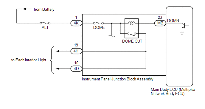
CAUTION / NOTICE / HINT

NOTICE:

  • Inspect the fuses for circuits related to this system before performing the following procedure.
  • Before replacing the main body ECU (multiplex network body ECU), refer to Registration.

    Click here

PROCEDURE

1.

PERFORM ACTIVE TEST USING TECHSTREAM

(a) Connect the Techstream to the DLC3.

(b) Turn the engine switch on (IG).

(c) Turn the Techstream on.

(d) Enter the following menus: Body Electrical / Main Body / Active Test.

(e) Perform the Active Test according to the display on the Techstream.

Body Electrical > Main Body > Active Test

Tester Display

Measurement Item

Control Range

Diagnostic Note

Relay for Interior Light Auto Cut Function

DOME CUT relay

OFF or ON

When performing this Active Test, turn all the interior lights on.

  • OFF: DOME CUT relay on (interior lights turn on)
  • ON: DOME CUT relay off (interior lights turn off)
Body Electrical > Main Body > Active Test

Tester Display

Relay for Interior Light Auto Cut Function

OK:

All of the interior lights turn off when ON is selected.

OK

PROCEED TO NEXT SUSPECTED AREA SHOWN IN PROBLEM SYMPTOMS TABLE

NG

2.

CHECK HARNESS AND CONNECTOR (POWER SOURCE - INSTRUMENT PANEL JUNCTION BLOCK ASSEMBLY)

(a) Disconnect the 4K instrument panel junction block assembly connector.

(b) Measure the voltage according to the value(s) in the table below.

Standard Voltage:

Tester Connection

Condition

Specified Condition

4K-1 - Body ground

Always

11 to 14 V

NG

REPAIR OR REPLACE HARNESS OR CONNECTOR

OK

3.

INSPECT INSTRUMENT PANEL JUNCTION BLOCK ASSEMBLY

*a

Component without harness connected

(Instrument Panel Junction Block Assembly)

-

-

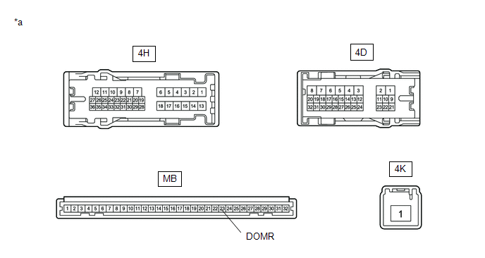
(a) Remove the main body ECU (multiplex network body ECU) from the instrument panel junction block assembly.

Click here

(b) Measure the voltage according to the value(s) in the table below.

Standard Voltage:

Tester Connection

Condition

Specified Condition

4H-19 - Battery negative (-)

Battery positive (+) → 4K-1

Battery negative (-) → MB-23 (DOMR)

11 to 14 V

4D-10 - Battery negative (-)

Battery positive (+) → 4K-1

Battery negative (-) → MB-23 (DOMR)

11 to 14 V

(c) Measure the resistance according to the value(s) in the table below.

Standard Resistance:

Tester Connection

Condition

Specified Condition

4K-1 - 4H-19

Always

10 kΩ or higher

4K-1 - 4D-10

Always

10 kΩ or higher

OK

REPLACE MAIN BODY ECU (MULTIPLEX NETWORK BODY ECU)

NG

REPLACE INSTRUMENT PANEL JUNCTION BLOCK ASSEMBLY

    IG Signal Circuit

    Interior Light Circuit

    See More:

    Toyota Avalon (XX50) 2019-2022 Service & Repair Manual > Heating / Air Conditioning: Front Blower Motor
    ComponentsCOMPONENTS ILLUSTRATION *1 BLOWER MOTOR WITH FAN SUB-ASSEMBLY *2 NO. 2 INSTRUMENT PANEL UNDER COVER SUB-ASSEMBLY InstallationINSTALLATION PROCEDURE 1. INSTALL BLOWER MOTOR WITH FAN SUB-ASSEMBLY (a) Install the blower motor with fan sub-assembly with the 3 screws. NOTICE: Replace the blowe ...

    Toyota Avalon (XX50) 2019-2022 Owners Manual

    Toyota Avalon (XX50) 2019-2022 Service & Repair Manual

    © 2024 Copyright www.tavalon.net
    0.0193