DESCRIPTION
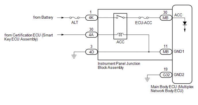
This circuit detects the engine switch on (ACC) or off condition, and sends it to the main body ECU (multiplex network body ECU).
WIRING DIAGRAM
CAUTION / NOTICE / HINT
NOTICE:
Click here 
Click here
PROCEDURE
|
1. | READ VALUE USING TECHSTREAM |
(a) Connect the Techstream to the DLC3.
(b) Turn the engine switch on (IG).
(c) Turn the Techstream on.
(d) Enter the following menus: Body Electrical / Main Body / Data List.
(e) Read the Data List according to the display on the Techstream.
Body Electrical > Main Body > Data List|
Tester Display | Measurement Item |
Range | Normal Condition |
Diagnostic Note |
|---|---|---|---|---|
|
ACC SW | Engine switch on (ACC) signal |
OFF or ON | OFF: Engine switch off ON: Engine switch on (ACC) |
"ON" is also displayed for this item when the engine switch is on (IG). |
|
Tester Display |
|---|
| ACC SW |
OK:
Normal conditions listed above are displayed.
| OK |  | PROCEED TO NEXT SUSPECTED AREA SHOWN IN PROBLEM SYMPTOMS TABLE |
|
| 2. |
CHECK HARNESS AND CONNECTOR (POWER SOURCE CIRCUIT) |
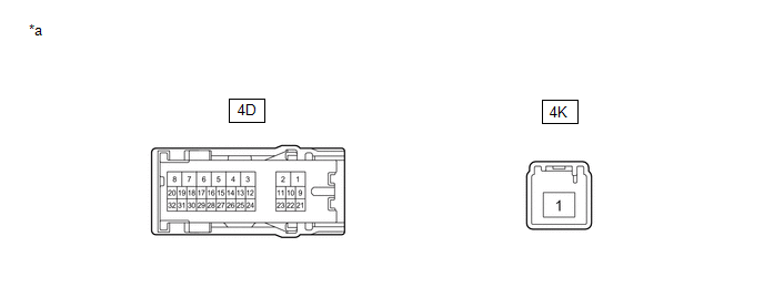
(a) Disconnect the 4K and 4D instrument panel junction block assembly connectors.
(b) Disconnect the G32 main body ECU (multiplex network body ECU) connector.
(c) Measure the voltage according to the value(s) in the table below.
Standard Voltage:
|
Tester Connection | Condition |
Specified Condition |
|---|---|---|
|
4K-1 - Body ground | Always |
11 to 14 V |
(d) Measure the resistance according to the value(s) in the table below.
Standard Resistance:
|
Tester Connection | Condition |
Specified Condition |
|---|---|---|
|
4D-3 - Body ground | Always |
Below 1 Ω |
|
G32-19 (GND2) - Body ground |
Always | Below 1 Ω |
| NG | | REPAIR OR REPLACE HARNESS OR CONNECTOR |
|
| 3. |
INSPECT INSTRUMENT PANEL JUNCTION BLOCK ASSEMBLY |

|
*a | Component without harness connected (Instrument Panel Junction Block Assembly) |
- | - |
(a) Remove the main body ECU (multiplex network body ECU) from the instrument panel junction block assembly.
Click here
(b) Measure the resistance according to the value(s) in the table below.
Standard Resistance:
|
Tester Connection | Condition |
Specified Condition |
|---|---|---|
|
4K-1 - MB-30 (ACC) | Battery not connected to 4A-30 and 4D-3 |
10 kΩ or higher |
|
4K-1 - MB-30 (ACC) | Battery positive (+) → 4A-30 Battery negative (-) → 4D-3 |
Below 1 Ω |
| OK | | REPLACE MAIN BODY ECU (MULTIPLEX NETWORK BODY ECU) |
| NG | | REPLACE INSTRUMENT PANEL JUNCTION BLOCK ASSEMBLY |
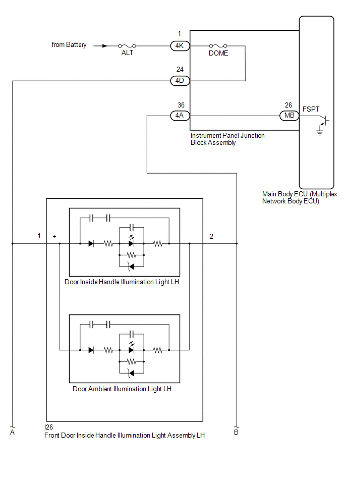
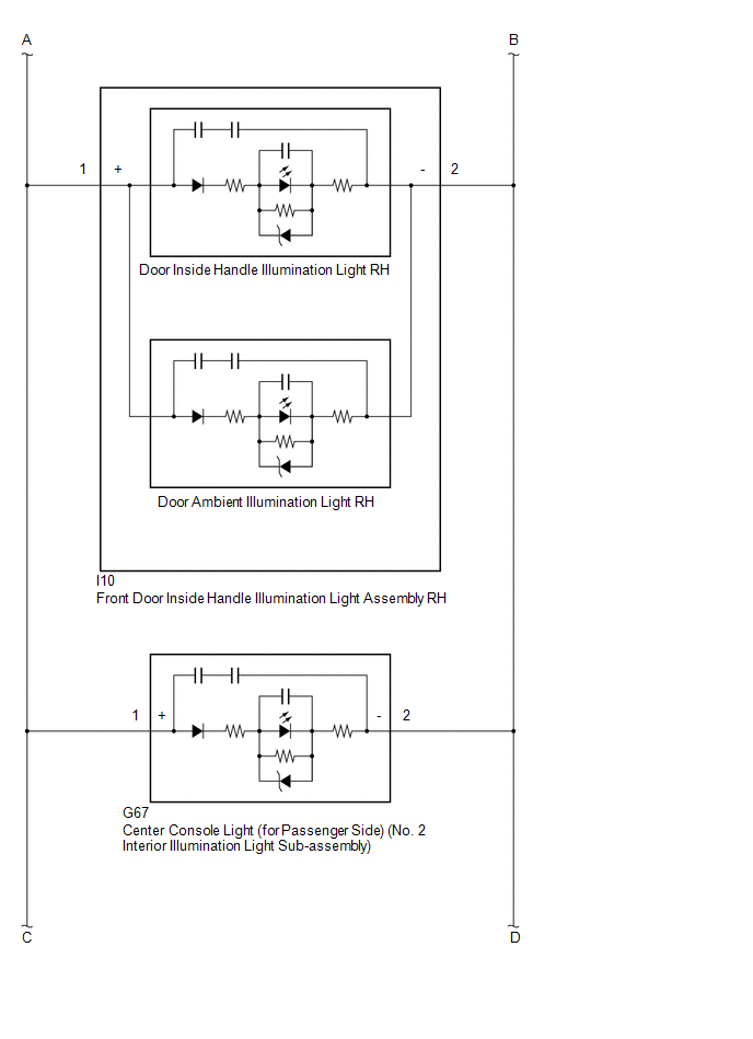
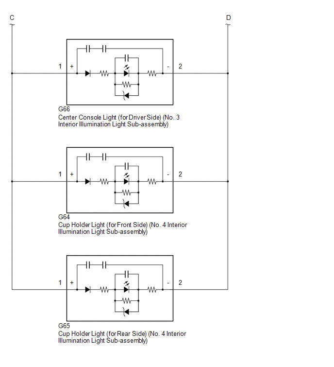
DESCRIPTION
The main body ECU (multiplex network body ECU) controls the operation of the following lights:
WIRING DIAGRAM
CAUTION / NOTICE / HINT
NOTICE:
Click here 
PROCEDURE
|
1. | PERFORM ACTIVE TEST USING TECHSTREAM |
(a) Connect the Techstream to the DLC3.
(b) Turn the engine switch on (IG).
(c) Turn the Techstream on.
(d) Enter the following menus: Body Electrical / Main Body / Active Test.
(e) Perform the Active Test according to the display on the Techstream.
Body Electrical > Main Body > Active Test|
Tester Display | Measurement Item |
Control Range | Diagnostic Note |
|---|---|---|---|
|
Fr Foot Light |
| OFF or ON |
Preconditions for using the Active Test to check dimmer controlled illumination:
|
|
Tester Display |
|---|
| Fr Foot Light |
OK:
Front door inside handle illumination lights, center console lights and cup holder lights come on.
|
Result | Proceed to |
|---|---|
|
OK | A |
|
NG (Front door inside handle illumination light LH does not come on) |
B |
| NG (Front door inside handle illumination light RH does not come on) |
C |
| NG (Center console light (for passenger side) does not come on) |
D |
| NG (Center console light (for driver side) does not come on) |
E |
| NG (Cup holder light (for front side) does not come on) |
F |
| NG (Cup holder light (for rear side) does not come on) |
G |
| NG (Front door inside handle illumination lights, center console lights and cup holder lights do not come on) |
H |
| A |
 | USE SIMULATION METHOD TO CHECK |
| C |
| GO TO STEP 4 |
| D |
| GO TO STEP 6 |
| E |
| GO TO STEP 8 |
| F |
| GO TO STEP 10 |
| G |
| GO TO STEP 12 |
| H |
| GO TO STEP 14 |
|
| 2. |
INSPECT FRONT DOOR INSIDE HANDLE ILLUMINATION LIGHT ASSEMBLY LH |
(a) Remove the front door inside handle illumination light assembly LH.
Click here
(b) Inspect the front door inside handle illumination light assembly LH.
Click here
| NG | | REPLACE FRONT DOOR INSIDE HANDLE ILLUMINATION LIGHT ASSEMBLY LH |
|
| 3. |
CHECK HARNESS AND CONNECTOR (INSTRUMENT PANEL JUNCTION BLOCK ASSEMBLY - FRONT DOOR INSIDE HANDLE ILLUMINATION LIGHT ASSEMBLY LH) |
(a) Disconnect the 4A and 4D instrument panel junction block assembly connector.
(b) Measure the resistance according to the value(s) in the table below.
Standard Resistance:
|
Tester Connection | Condition |
Specified Condition |
|---|---|---|
|
4D-24 - I26-1 (+) | Always |
Below 1 Ω |
|
4A-36 - I26-2 (-) | Always |
Below 1 Ω |
| OK | | USE SIMULATION METHOD TO CHECK |
| NG | | REPAIR OR REPLACE HARNESS OR CONNECTOR |
| 4. |
INSPECT FRONT DOOR INSIDE HANDLE ILLUMINATION LIGHT ASSEMBLY RH |
(a) Remove the front door inside handle illumination light assembly RH.
Click here
(b) Inspect the front door inside handle illumination light assembly RH.
Click here
| NG | | REPLACE FRONT DOOR INSIDE HANDLE ILLUMINATION LIGHT ASSEMBLY RH |
|
| 5. |
CHECK HARNESS AND CONNECTOR (INSTRUMENT PANEL JUNCTION BLOCK ASSEMBLY - FRONT DOOR INSIDE HANDLE ILLUMINATION LIGHT ASSEMBLY RH) |
(a) Disconnect the 4A and 4D instrument panel junction block assembly connector.
(b) Measure the resistance according to the value(s) in the table below.
Standard Resistance:
|
Tester Connection | Condition |
Specified Condition |
|---|---|---|
|
4D-24 - I10-1 (+) | Always |
Below 1 Ω |
|
4A-36 - I10-2 (-) | Always |
Below 1 Ω |
| OK | | USE SIMULATION METHOD TO CHECK |
| NG | | REPAIR OR REPLACE HARNESS OR CONNECTOR |
| 6. |
INSPECT CENTER CONSOLE LIGHT (for Passenger Side) (NO. 2 INTERIOR ILLUMINATION LIGHT SUB-ASSEMBLY) |
(a) Remove the center console light (for passenger side) (No. 2 interior illumination light sub-assembly).
Click here
(b) Inspect the center console light (for passenger side) (No. 2 interior illumination light sub-assembly).
Click here
| NG | | REPLACE CENTER CONSOLE LIGHT (for Passenger Side) (NO. 2 INTERIOR ILLUMINATION LIGHT SUB-ASSEMBLY) |
|
| 7. |
CHECK HARNESS AND CONNECTOR (INSTRUMENT PANEL JUNCTION BLOCK ASSEMBLY - CENTER CONSOLE LIGHT (for Passenger Side)) |
(a) Disconnect the 4A and 4D instrument panel junction block assembly connector.
(b) Measure the resistance according to the value(s) in the table below.
Standard Resistance:
|
Tester Connection | Condition |
Specified Condition |
|---|---|---|
|
4D-24 - G67-1 (+) | Always |
Below 1 Ω |
|
4A-36 - G67-2 (-) | Always |
Below 1 Ω |
| OK | | USE SIMULATION METHOD TO CHECK |
| NG | | REPAIR OR REPLACE HARNESS OR CONNECTOR |
| 8. |
INSPECT CENTER CONSOLE LIGHT (for Driver Side) (NO. 3 INTERIOR ILLUMINATION LIGHT SUB-ASSEMBLY) |
(a) Remove the center console light (for driver side) (No. 3 interior illumination light sub-assembly).
Click here
(b) Inspect the center console light (for driver side) (No. 3 interior illumination light sub-assembly).
Click here
| NG | | REPLACE CENTER CONSOLE LIGHT (for Driver Side) (NO. 3 INTERIOR ILLUMINATION LIGHT SUB-ASSEMBLY) |
|
| 9. |
CHECK HARNESS AND CONNECTOR (INSTRUMENT PANEL JUNCTION BLOCK ASSEMBLY - CENTER CONSOLE LIGHT (for Driver Side)) |
(a) Disconnect the 4A and 4D instrument panel junction block assembly connector.
(b) Measure the resistance according to the value(s) in the table below.
Standard Resistance:
|
Tester Connection | Condition |
Specified Condition |
|---|---|---|
|
4D-24 - G66-1 (+) | Always |
Below 1 Ω |
|
4A-36 - G66-2 (-) | Always |
Below 1 Ω |
| OK | | USE SIMULATION METHOD TO CHECK |
| NG | | REPAIR OR REPLACE HARNESS OR CONNECTOR |
| 10. |
INSPECT CUP HOLDER LIGHT (for Front Side) (NO. 4 INTERIOR ILLUMINATION LIGHT SUB-ASSEMBLY) |
(a) Remove the cup holder light (for front side) (No. 4 interior illumination light sub-assembly).
Click here
(b) Inspect the cup holder light (for front side) (No. 4 interior illumination light sub-assembly).
Click here
| NG | | REPLACE CUP HOLDER LIGHT (for Front Side) (NO. 4 INTERIOR ILLUMINATION LIGHT SUB-ASSEMBLY) |
|
| 11. |
CHECK HARNESS AND CONNECTOR (INSTRUMENT PANEL JUNCTION BLOCK ASSEMBLY - CUP HOLDER LIGHT (for Front Side)) |
(a) Disconnect the 4A and 4D instrument panel junction block assembly connector.
(b) Measure the resistance according to the value(s) in the table below.
Standard Resistance:
|
Tester Connection | Condition |
Specified Condition |
|---|---|---|
|
4D-24 - G64-1 (+) | Always |
Below 1 Ω |
|
4A-36 - G64-2 (-) | Always |
Below 1 Ω |
| OK | | USE SIMULATION METHOD TO CHECK |
| NG | | REPAIR OR REPLACE HARNESS OR CONNECTOR |
| 12. |
INSPECT CUP HOLDER LIGHT (for Rear Side) (NO. 4 INTERIOR ILLUMINATION LIGHT SUB-ASSEMBLY) |
(a) Remove the cup holder light (for rear side) (No. 4 interior illumination light sub-assembly).
Click here
(b) Inspect the cup holder light (for rear side) (No. 4 interior illumination light sub-assembly).
Click here
| NG | | REPLACE CUP HOLDER LIGHT (for Rear Side) (NO. 4 INTERIOR ILLUMINATION LIGHT SUB-ASSEMBLY) |
|
| 13. |
CHECK HARNESS AND CONNECTOR (INSTRUMENT PANEL JUNCTION BLOCK ASSEMBLY - CUP HOLDER LIGHT (for Rear Side)) |
(a) Disconnect the 4A and 4D instrument panel junction block assembly connector.
(b) Measure the resistance according to the value(s) in the table below.
Standard Resistance:
|
Tester Connection | Condition |
Specified Condition |
|---|---|---|
|
4D-24 - G65-1 (+) | Always |
Below 1 Ω |
|
4A-36 - G65-2 (-) | Always |
Below 1 Ω |
| OK | | USE SIMULATION METHOD TO CHECK |
| NG | | REPAIR OR REPLACE HARNESS OR CONNECTOR |
| 14. |
CHECK HARNESS AND CONNECTOR (POWER SOURCE - INSTRUMENT PANEL JUNCTION BLOCK ASSEMBLY) |
(a) Disconnect the 4K instrument panel junction block assembly connector.
(b) Measure the voltage according to the value(s) in the table below.
Standard Voltage:
|
Tester Connection | Condition |
Specified Condition |
|---|---|---|
|
4K-1 - Body ground | Always |
11 to 14 V |
| NG | | REPAIR OR REPLACE HARNESS OR CONNECTOR |
|
| 15. |
CHECK INSTRUMENT PANEL JUNCTION BLOCK ASSEMBLY |
|
*a | Component without harness connected (Instrument Panel Junction Block Assembly) |
- | - |
(a) Disconnect the 4D instrument panel junction block assembly connector.
(b) Measure the resistance according to the value(s) in the table below.
Standard Resistance:
|
Tester Connection | Condition |
Specified Condition |
|---|---|---|
|
4D-24 - 4K-1 | Always |
Below 1 Ω |
| NG | | REPLACE INSTRUMENT PANEL JUNCTION BLOCK ASSEMBLY |
|
| 16. |
CHECK HARNESS AND CONNECTOR (INSTRUMENT PANEL JUNCTION BLOCK ASSEMBLY - AMBIENT ILLUMINATION LIGHT) |
(a) Disconnect the I26 front door inside handle illumination light assembly LH connector.
(b) Disconnect the I10 front door inside handle illumination light assembly RH connector.
(c) Disconnect the G67 center console light (for passenger side) (No. 2 interior illumination light sub-assembly) connector.
(d) Disconnect the G66 center console light (for driver side) (No. 3 interior illumination light sub-assembly) connector.
(e) Disconnect the G64 cup holder light (for front side) (No. 4 interior illumination light sub-assembly) connector.
(f) Disconnect the G65 cup holder light (for rear side) (No. 4 interior illumination light sub-assembly) connector.
(g) Measure the resistance according to the value(s) in the table below.
Standard Resistance:
|
Tester Connection | Condition |
Specified Condition |
|---|---|---|
|
4D-24 - I26-1 (+) | Always |
Below 1 Ω |
|
4D-24 - I10-1 (+) | Always |
Below 1 Ω |
|
4D-24 - G64-1 (+) | Always |
Below 1 Ω |
|
4D-24 - G65-1 (+) | Always |
Below 1 Ω |
|
4D-24 - G66-1 (+) | Always |
Below 1 Ω |
|
4D-24 - G67-1 (+) | Always |
Below 1 Ω |
|
4A-36 - I26-2 (-) | Always |
Below 1 Ω |
|
4A-36 - I10-2 (-) | Always |
Below 1 Ω |
|
4A-36 - G64-2 (-) | Always |
Below 1 Ω |
|
4A-36 - G65-2 (-) | Always |
Below 1 Ω |
|
4A-36 - G66-2 (-) | Always |
Below 1 Ω |
|
4A-36 - G67-2 (-) | Always |
Below 1 Ω |
|
4D-24, I26-1 (+), I10-1 (+), G64-1 (+), G65-1 (+), G66-1 (+) or G67-1 (+) - Body ground |
Always | 10 kΩ or higher |
|
4A-36, I26-2 (-), I10-2 (-), G64-2 (-), G65-2 (-), G66-2 (-) or G67-2 (-) - Body ground |
Always | 10 kΩ or higher |
| NG | | REPAIR OR REPLACE HARNESS OR CONNECTOR |
|
| 17. |
INSPECT INSTRUMENT PANEL JUNCTION BLOCK ASSEMBLY |
|
*a | Component without harness connected (Instrument Panel Junction Block Assembly) |
- | - |
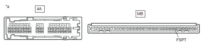
(a) Remove the main body ECU (multiplex network body ECU) from the instrument panel junction block assembly.
Click here
(b) Measure the resistance according to the value(s) in the table below.
Standard Resistance:
|
Tester Connection | Condition |
Specified Condition |
|---|---|---|
|
4A-36 - MB-26 (FSPT) |
Always | Below 1 Ω |
| OK | | REPLACE MAIN BODY ECU (MULTIPLEX NETWORK BODY ECU) |
| NG | | REPLACE INSTRUMENT PANEL JUNCTION BLOCK ASSEMBLY |
DESCRIPTION
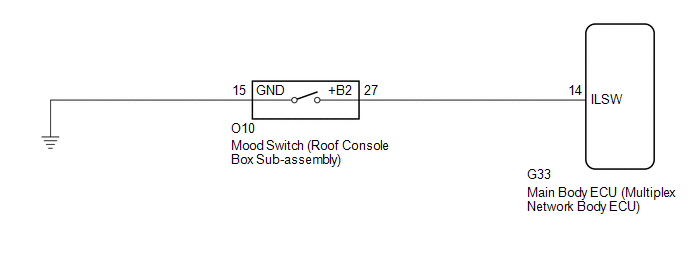
The main body ECU (multiplex network body ECU) detects the condition of the mood switch on the roof console box sub-assembly using this circuit.
WIRING DIAGRAM
CAUTION / NOTICE / HINT
NOTICE:
Before replacing the main body ECU (multiplex network body ECU), refer to Registration.
Click here 
PROCEDURE
| 1. |
READ VALUE USING TECHSTREAM |
(a) Connect the Techstream to the DLC3.
(b) Turn the engine switch on (IG).
(c) Turn the Techstream on.
(d) Enter the following menus: Body Electrical / Main Body / Data List.
(e) Read the Data List according to the display on the Techstream.
Body Electrical > Main Body > Data List|
Tester Display | Measurement Item |
Range | Normal Condition |
Diagnostic Note |
|---|---|---|---|---|
|
Ceiling Light SW | Mood switch signal |
OFF or ON | OFF: Mood switch not pressed ON: Mood switch pressed |
- |
|
Tester Display |
|---|
| Ceiling Light SW |
OK:
Normal conditions listed above are displayed.
| OK |  | PROCEED TO NEXT SUSPECTED AREA SHOWN IN PROBLEM SYMPTOMS TABLE |
|
| 2. |
INSPECT MOOD SWITCH (ROOF CONSOLE BOX SUB-ASSEMBLY) |
(a) Remove the mood switch (roof console box sub-assembly).
Click here
(b) Inspect the mood switch (roof console box sub-assembly).
Click here
| NG | | REPLACE MOOD SWITCH (ROOF CONSOLE BOX SUB-ASSEMBLY) |
|
| 3. |
CHECK HARNESS AND CONNECTOR (MOOD SWITCH (ROOF CONSOLE BOX SUB-ASSEMBLY) - MAIN BODY ECU (MULTIPLEX NETWORK BODY ECU) AND BODY GROUND) |
(a) Disconnect the G33 main body ECU (multiplex network body ECU) connector.
(b) Measure the resistance according to the value(s) in the table below.
Standard Resistance:
|
Tester Connection | Condition |
Specified Condition |
|---|---|---|
|
O10-27 (+B2) - G33-14 (ILSW) |
Always | Below 1 Ω |
|
O10-27 (+B2) or G33-14 (ILSW) - Body ground |
Always | 10 kΩ or higher |
|
O10-15 (GND) - Body ground |
Always | Below 1 Ω |
| OK | | REPLACE MAIN BODY ECU (MULTIPLEX NETWORK BODY ECU) |
| NG | | REPAIR OR REPLACE HARNESS OR CONNECTOR |
CUSTOMIZE PARAMETERS
CUSTOMIZE LIGHTING SYSTEM (INT)
NOTICE:
HINT:
The following items can be customized.
(a) Customizing using the Techstream
(1) Connect the Techstream to the DLC3.
(2) Turn the engine switch on (IG).
(3) Turn the Techstream on.
(4) Enter the following menus: Customize Setting / Illuminated Entry.
(5) Select the setting by referring to the table below.
Illuminated Entry|
Tester Display | Description |
Default | Setting |
ECU |
|---|---|---|---|---|
| Lighting Time |
Changes the lighting time of the following lights that are operated by the timer function when the door linked switch of the map light (roof console box sub-assembly) is on:
| 15 s |
10:30 s,00:15 s,01:7.5 s |
Main body ECU (Multiplex network body ECU) |
|
I/L when ACC OFF | Lights up the following lights automatically when the door linked switch of the map light (roof console box sub-assembly) is on and the engine switch is turned from on (ACC) or on (IG) to off:
| ON |
0:OFF,1:ON | Main body ECU (Multiplex network body ECU) |
|
I/L ON W/Door Key Unlock |
Lights up the following lights automatically when the door linked switch of the map light (roof console box sub-assembly) is on and the doors are unlocked by an unlock operation:
| ON |
0:OFF,1:ON | Main body ECU (Multiplex network body ECU) |
|
Room Light when Aprchd |
Lights up the following lights when the door linked switch of the map light (roof console box sub-assembly) is on and the electrical key transmitter sub-assembly is brought near the vehicle:
| ON |
0:OFF,1:ON | Main body ECU (Multiplex network body ECU) |
|
Light Control | Dims the lights when the engine switch is on (IG) and the shift lever is moved to any position other than P*2 |
ON | 0:OFF,1:ON |
Main body ECU (Multiplex network body ECU) |
|
Interior Light Control |
Lights up the following lights:
| ON |
0:OFF,1:ON | Main body ECU (Multiplex network body ECU) |
|
Interior Illumination Light |
Turns on the following lights:
| ON |
0:OFF,1:ON | Main body ECU (Multiplex network body ECU) |
(b) Customizing with the multi-display
(1) Turn the engine switch on (IG).
(2) Enter the following menus: MENU / Setup / Vehicle / Vehicle Customization / Lights Settings.
(3) Select the setting by referring to the table below.
|
Display | Default |
Content | Setting |
Relevant ECU |
|---|---|---|---|---|
| Interior Lights Auto-off Timer |
15 sec. | Changes the lighting time of the following lights that are operated by the timer function when the door linked switch of the map light (roof console box sub-assembly) is on:
| Off, 7.5 sec., 15 sec., 30 sec. |
Main body ECU (Multiplex network body ECU) |
DATA LIST / ACTIVE TEST
DATA LIST
NOTICE:
In the following table, the values listed under "Normal Condition" are reference values. Do not depend solely on these reference values when deciding whether a part is faulty or not.
HINT:
Using the Techstream to read the Data List allows the values or states of switches, sensors, actuators and other items to be read without removing any parts. This non-intrusive inspection can be very useful because intermittent conditions or signals may be discovered before parts or wiring is disturbed. Reading the Data List information early in troubleshooting is one way to save diagnostic time.
(a) Connect the Techstream to the DLC3.
(b) Turn the engine switch on (IG).
(c) Turn the Techstream on.
(d) Enter the following menus: Body Electrical / Main Body / Data List.
(e) Read the Data List according to the display on the Techstream.
Body Electrical > Main Body > Data List|
Tester Display | Measurement Item |
Range | Normal Condition |
Diagnostic Note |
|---|---|---|---|---|
|
ACC SW | Engine switch on (ACC) signal |
OFF or ON | OFF: Engine switch off ON: Engine switch on (ACC) |
"ON" is also displayed for this item when the engine switch is on (IG). |
|
IG SW | Engine switch on (IG) signal |
OFF or ON | OFF: Engine switch off ON: Engine switch on (IG) |
"OFF" is also displayed for this item when the engine switch is on (ACC). |
|
RR Door Courtesy SW | Rear door courtesy light switch assembly (for RH) signal |
OFF or ON | OFF: Rear door RH closed ON: Rear door RH open |
- |
| RL Door Courtesy SW |
Rear door courtesy light switch assembly (for LH) signal |
OFF or ON | OFF: Rear door LH closed ON: Rear door LH open |
- |
| FR Door Lock Pos |
Front door RH unlock detection switch signal |
LOCK or UNLOCK | LOCK: Front door RH locked UNLOCK: Front door RH unlocked |
- |
| FR Door Courtesy SW |
Front door courtesy light switch assembly (for RH) signal |
OFF or ON | OFF: Front door RH closed ON: Front door RH open |
- |
| FL Door Lock Pos |
Front door LH unlock detection switch signal |
LOCK or UNLOCK | LOCK: Front door LH locked UNLOCK: Front door LH unlocked |
- |
| FL Door Courtesy SW |
Front door courtesy light switch assembly (for LH) signal |
OFF or ON | OFF: Front door LH closed ON: Front door LH open |
- |
| Ceiling Light SW |
Mood switch signal* | OFF or ON |
OFF: Mood switch not pressed ON: Mood switch pressed |
- |
| RR-Door Lock Pos SW |
Rear door RH unlock detection switch signal |
OFF or ON | OFF: Rear door RH locked ON: Rear door RH unlocked |
- |
| RL-Door Lock Pos SW |
Rear door LH unlock detection switch signal |
OFF or ON | OFF: Rear door LH locked ON: Rear door LH unlocked |
- |
| Luggage Courtesy SW |
Luggage compartment door courtesy switch signal |
OFF or ON | OFF: Luggage compartment door closed ON: Luggage compartment door open |
- |
| Interior Light Control |
Operation of the illuminated entry system |
OFF or ON | Customized value is displayed |
- |
| I/L ON W/Door Key Unlock |
Function that turns on the interior lights when the doors are unlocked |
OFF or ON | Customized value is displayed |
- |
| Lighting Time |
Lighting time of the delay control function (illuminated entry system) |
15 s, 7.5 s or 30 s | Customized value is displayed |
- |
| Room Light when Aprchd |
Function that turns on the interior lights when a key enters any actuation area |
OFF or ON | Customized value is displayed |
- |
| I/L when ACC OFF |
Function that turns on the interior lights when the engine switch is turned from on (ACC) or on (IG) to off |
OFF or ON | Customized value is displayed |
- |
| Light Control |
Function that dims the lights when the engine switch is on (IG) and the shift lever is moved to any position other than P |
OFF or ON | Customized value is displayed |
Although this item is displayed on the Techstream, it is not applicable to this vehicle. |
|
Interior Illumination Light |
Function that turns on the following lights:
| OFF or ON |
Customized value is displayed |
- |
ACTIVE TEST
HINT:
Using the Techstream to perform Active Tests allows relays, VSVs, actuators and other items to be operated without removing any parts. This non-intrusive functional inspection can be very useful because intermittent operation may be discovered before parts or wiring is disturbed. Performing Active Tests early in troubleshooting is one way to save diagnostic time. Data List information can be displayed while performing Active Tests.
(a) Connect the Techstream to the DLC3.
(b) Turn the engine switch on (IG).
(c) Turn the Techstream on.
(d) Enter the following menus: Body Electrical / (desired system) / Active Test.
(e) Perform the Active Test according to the display on the Techstream.
Body Electrical > Main Body > Active Test|
Tester Display | Measurement Item |
Control Range | Diagnostic Note |
|---|---|---|---|
|
Illuminated Entry System |
Turns on the lights that are controlled by the illuminated entry system*1 |
OFF or ON | Perform the Active Test with the door linked switch of the map light (roof console box sub-assembly) on and switches of the spot light assembly LH and RH off. |
| Fr Foot Light |
| OFF or ON |
Preconditions for using the Active Test to check dimmer controlled illumination:
|
| Relay for Interior Light Auto Cut Function |
DOME CUT relay | OFF or ON |
When performing this Active Test, turn all the interior lights on.
|
Click here 
|
Tester Display | Measurement Item |
Control Range | Diagnostic Note |
|---|---|---|---|
|
Power/Engine SW Light | Engine switch illumination |
OFF or ON | - |
DIAGNOSIS SYSTEM
DESCRIPTION
(a) Lighting system data and Diagnostic Trouble Codes (DTCs) can be read from the Data Link Connector 3 (DLC3) of the vehicle. When the system seems to be malfunctioning, use the Techstream to check for malfunctions and perform repairs.
CHECK DLC3
(a) Check the DLC3.
Click here

INSPECT BATTERY VOLTAGE
(a) Measure the battery voltage.
Standard Voltage:
11 to 14 V
If the voltage is below 11 V, recharge or replace the battery.
DESCRIPTION
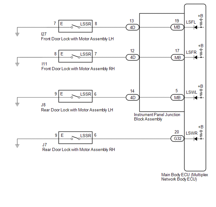
The main body ECU (multiplex network body ECU) detects the condition of each door unlock detection switch.
WIRING DIAGRAM
CAUTION / NOTICE / HINT
NOTICE:
Before replacing the main body ECU (multiplex network body ECU), refer to Registration.
Click here 
PROCEDURE
| 1. |
READ VALUE USING TECHSTREAM |
(a) Connect the Techstream to the DLC3.
(b) Turn the engine switch on (IG).
(c) Turn the Techstream on.
(d) Enter the following menus: Body Electrical / Main Body / Data List.
(e) Read the Data List according to the display on the Techstream.
Body Electrical > Main Body > Data List|
Tester Display | Measurement Item |
Range | Normal Condition |
Diagnostic Note |
|---|---|---|---|---|
|
FR Door Lock Pos | Front door RH unlock detection switch signal |
LOCK or UNLOCK | LOCK: Front door RH locked UNLOCK: Front door RH unlocked |
- |
| FL Door Lock Pos |
Front door LH unlock detection switch signal |
LOCK or UNLOCK | LOCK: Front door LH locked UNLOCK: Front door LH unlocked |
- |
| RR-Door Lock Pos SW |
Rear door RH unlock detection switch signal |
OFF or ON | OFF: Rear door RH locked ON: Rear door RH unlocked |
- |
| RL-Door Lock Pos SW |
Rear door LH unlock detection switch signal |
OFF or ON | OFF: Rear door LH locked ON: Rear door LH unlocked |
- |
|
Tester Display |
|---|
| FR Door Lock Pos |
|
FL Door Lock Pos |
|
RR-Door Lock Pos SW |
|
RL-Door Lock Pos SW |
OK:
Normal conditions listed above are displayed.
|
Result | Proceed to |
|---|---|
|
OK | A |
|
NG ("FL Door Lock Pos" is not normal) |
B |
| NG ("FR Door Lock Pos" is not normal) |
C |
| NG ("RL-Door Lock Pos SW" is not normal) |
D |
| NG ("RR-Door Lock Pos SW" is not normal) |
E |
| A |
 | PROCEED TO NEXT SUSPECTED AREA SHOWN IN PROBLEM SYMPTOMS TABLE |
| C |
| GO TO STEP 5 |
| D |
| GO TO STEP 8 |
| E |
| GO TO STEP 11 |
|
| 2. |
INSPECT FRONT DOOR LOCK WITH MOTOR ASSEMBLY LH |
(a) Remove the front door lock with motor assembly LH.
Click here
(b) Inspect the front door lock with motor assembly LH.
Click here
| NG | | REPLACE FRONT DOOR W/MOTOR LOCK ASSEMBLY LH |
|
| 3. |
CHECK HARNESS AND CONNECTOR (FRONT DOOR LOCK WITH MOTOR ASSEMBLY LH - INSTRUMENT PANEL JUNCTION BLOCK ASSEMBLY AND BODY GROUND) |
(a) Disconnect the 4D instrument panel junction block assembly connector.
(b) Measure the resistance according to the value(s) in the table below.
Standard Resistance:
|
Tester Connection | Condition |
Specified Condition |
|---|---|---|
|
I27-8 (LSSR) - 4D-13 |
Always | Below 1 Ω |
|
I27-8 (LSSR) or 4D-13 - Body ground |
Always | 10 kΩ or higher |
|
I27-7 (E) - Body ground |
Always | Below 1 Ω |
| NG | | REPAIR OR REPLACE HARNESS OR CONNECTOR |
|
| 4. |
INSPECT INSTRUMENT PANEL JUNCTION BLOCK ASSEMBLY |
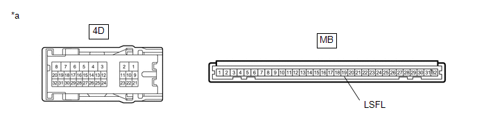
|
*a | Component without harness connected (Instrument Panel Junction Block Assembly) |
- | - |
(a) Remove the main body ECU (multiplex network body ECU) from the instrument panel junction block assembly.
Click here
(b) Measure the resistance according to the value(s) in the table below.
Standard Resistance:
|
Tester Connection | Condition |
Specified Condition |
|---|---|---|
|
4D-13 - MB-19 (LSFL) |
Always | Below 1 Ω |
| OK | | REPLACE MAIN BODY ECU (MULTIPLEX NETWORK BODY ECU) |
| NG | | REPLACE INSTRUMENT PANEL JUNCTION BLOCK ASSEMBLY |
| 5. |
INSPECT FRONT DOOR LOCK WITH MOTOR ASSEMBLY RH |
(a) Remove the front door lock with motor assembly RH.
Click here
(b) Inspect the front door lock with motor assembly RH.
Click here
| NG | | REPLACE FRONT DOOR LOCK WITH MOTOR ASSEMBLY RH |
|
| 6. |
CHECK HARNESS AND CONNECTOR (FRONT DOOR LOCK WITH MOTOR ASSEMBLY RH - INSTRUMENT PANEL JUNCTION BLOCK ASSEMBLY AND BODY GROUND) |
(a) Disconnect the 4D instrument panel junction block assembly connector.
(b) Measure the resistance according to the value(s) in the table below.
Standard Resistance:
|
Tester Connection | Condition |
Specified Condition |
|---|---|---|
|
I11-7 (LSSR) - 4D-12 |
Always | Below 1 Ω |
|
I11-7 (LSSR) or 4D-12 - Body ground |
Always | 10 kΩ or higher |
|
I11-8 (E) - Body ground |
Always | Below 1 Ω |
| NG | | REPAIR OR REPLACE HARNESS OR CONNECTOR |
|
| 7. |
INSPECT INSTRUMENT PANEL JUNCTION BLOCK ASSEMBLY |
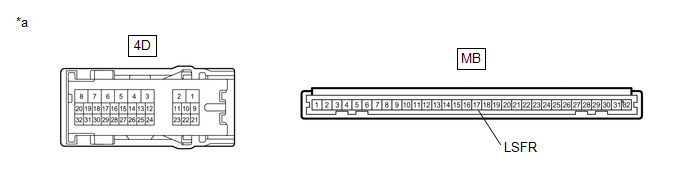
|
*a | Component without harness connected (Instrument Panel Junction Block Assembly) |
- | - |
(a) Remove the main body ECU (multiplex network body ECU) from the instrument panel junction block assembly.
Click here
(b) Measure the resistance according to the value(s) in the table below.
Standard Resistance:
|
Tester Connection | Condition |
Specified Condition |
|---|---|---|
|
4D-12 - MB-17 (LSFR) |
Always | Below 1 Ω |
| OK | | REPLACE MAIN BODY ECU (MULTIPLEX NETWORK BODY ECU) |
| NG | | REPLACE INSTRUMENT PANEL JUNCTION BLOCK ASSEMBLY |
| 8. |
INSPECT REAR DOOR LOCK WITH MOTOR ASSEMBLY LH |
(a) Remove the rear door lock with motor assembly LH.
Click here
(b) Inspect the rear door lock with motor assembly LH.
Click here
| NG | | REPLACE REAR DOOR W/MOTOR LOCK ASSEMBLY LH |
|
| 9. |
CHECK HARNESS AND CONNECTOR (REAR DOOR LOCK WITH MOTOR ASSEMBLY LH - INSTRUMENT PANEL JUNCTION BLOCK ASSEMBLY AND BODY GROUND) |
(a) Disconnect the 4D instrument panel junction block assembly connector.
(b) Measure the resistance according to the value(s) in the table below.
Standard Resistance:
|
Tester Connection | Condition |
Specified Condition |
|---|---|---|
|
J8-6 (LSSR) - 4D-14 | Always |
Below 1 Ω |
|
J8-6 (LSSR) or 4D-14 - Body ground |
Always | 10 kΩ or higher |
|
J8-9 (E) - Body ground |
Always | Below 1 Ω |
| NG | | REPAIR OR REPLACE HARNESS OR CONNECTOR |
|
| 10. |
INSPECT INSTRUMENT PANEL JUNCTION BLOCK ASSEMBLY |
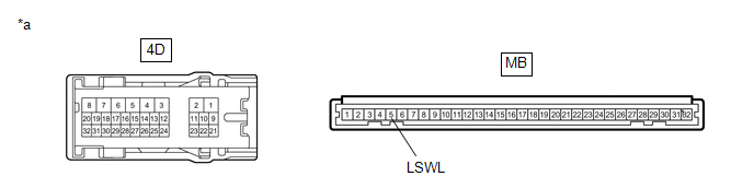
|
*a | Component without harness connected (Instrument Panel Junction Block Assembly) |
- | - |
(a) Remove the main body ECU (multiplex network body ECU) from the instrument panel junction block assembly.
Click here
(b) Measure the resistance according to the value(s) in the table below.
Standard Resistance:
|
Tester Connection | Condition |
Specified Condition |
|---|---|---|
|
4D-14 - MB-5 (LSWL) | Always |
Below 1 Ω |
| OK | | REPLACE MAIN BODY ECU (MULTIPLEX NETWORK BODY ECU) |
| NG | | REPLACE INSTRUMENT PANEL JUNCTION BLOCK ASSEMBLY |
| 11. |
INSPECT REAR DOOR LOCK WITH MOTOR ASSEMBLY RH |
(a) Remove the rear door lock with motor assembly RH.
Click here
(b) Inspect the rear door lock with motor assembly RH.
Click here
| NG | | REPLACE REAR DOOR LOCK WITH MOTOR ASSEMBLY RH |
|
| 12. |
CHECK HARNESS AND CONNECTOR (REAR DOOR LOCK WITH MOTOR ASSEMBLY RH - MAIN BODY ECU (MULTIPLEX NETWORK BODY ECU) AND BODY GROUND) |
(a) Disconnect the G32 main body ECU (multiplex network body ECU) connector.
(b) Measure the resistance according to the value(s) in the table below.
Standard Resistance:
|
Tester Connection | Condition |
Specified Condition |
|---|---|---|
|
J7-6 (LSSR) - G32-20 (LSWR) |
Always | Below 1 Ω |
|
J7-6 (LSSR) or G32-20 (LSWR) - Body ground |
Always | 10 kΩ or higher |
|
J7-9 (E) - Body ground |
Always | Below 1 Ω |
| OK | | REPLACE MAIN BODY ECU (MULTIPLEX NETWORK BODY ECU) |
| NG | | REPAIR OR REPLACE HARNESS OR CONNECTOR |
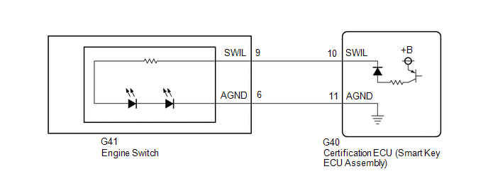
DESCRIPTION
The illuminated entry system controls the engine switch illumination.
WIRING DIAGRAM
CAUTION / NOTICE / HINT
NOTICE:
Before replacing the certification ECU (smart key ECU assembly), refer to Registration.
Click here 
PROCEDURE
| 1. |
PERFORM ACTIVE TEST USING TECHSTREAM |
(a) Connect the Techstream to the DLC3.
(b) Turn the engine switch on (IG).
(c) Turn the Techstream on.
(d) Enter the following menus: Body Electrical / Smart Key / Active Test.
(e) Perform the Active Test according to the display on the Techstream.
Body Electrical > Smart Key > Active Test|
Tester Display | Measurement Item |
Control Range | Diagnostic Note |
|---|---|---|---|
|
Power/Engine SW Light | Engine switch illumination |
OFF or ON | - |
|
Tester Display |
|---|
| Power/Engine SW Light |
OK:
Engine switch illumination comes on.
| OK |  | PROCEED TO NEXT SUSPECTED AREA SHOWN IN PROBLEM SYMPTOMS TABLE |
|
| 2. |
INSPECT ENGINE SWITCH |
(a) Remove the engine switch.
Click here
(b) Inspect the engine switch.
Click here
| NG | | REPLACE ENGINE SWITCH |
|
| 3. |
CHECK HARNESS AND CONNECTOR (ENGINE SWITCH - CERTIFICATION ECU (SMART KEY ECU ASSEMBLY)) |
(a) Disconnect the G40 certification ECU (smart key ECU assembly) connector.
(b) Measure the resistance according to the value(s) in the table below.
Standard Resistance:
|
Tester Connection | Condition |
Specified Condition |
|---|---|---|
|
G41-9 (SWIL) - G40-10 (SWIL) |
Always | Below 1 Ω |
|
G41-6 (AGND) - G40-11 (AGND) |
Always | Below 1 Ω |
|
G41-9 (SWIL) or G40-10 (SWIL) - Body ground |
Always | 10 kΩ or higher |
|
G41-6 (AGND) or G40-11 (AGND) - Body ground |
Always | 10 kΩ or higher |
| OK | | REPLACE CERTIFICATION ECU (SMART KEY ECU ASSEMBLY) |
| NG | | REPAIR OR REPLACE HARNESS OR CONNECTOR |
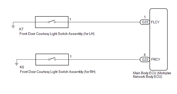
DESCRIPTION
The main body ECU (multiplex network body ECU) detects the condition of the front door courtesy light switch assembly.
WIRING DIAGRAM
CAUTION / NOTICE / HINT
NOTICE:
Before replacing the main body ECU (multiplex network body ECU), refer to Registration.
Click here 
PROCEDURE
| 1. |
READ VALUE USING TECHSTREAM |
(a) Connect the Techstream to the DLC3.
(b) Turn the engine switch on (IG).
(c) Turn the Techstream on.
(d) Enter the following menus: Body Electrical / Main Body / Data List.
(e) Read the Data List according to the display on the Techstream.
Body Electrical > Main Body > Data List|
Tester Display | Measurement Item |
Range | Normal Condition |
Diagnostic Note |
|---|---|---|---|---|
|
FR Door Courtesy SW | Front door courtesy light switch assembly (for RH) signal |
OFF or ON | OFF: Front door RH closed ON: Front door RH open |
- |
| FL Door Courtesy SW |
Front door courtesy light switch assembly (for LH) signal |
OFF or ON | OFF: Front door LH closed ON: Front door LH open |
- |
|
Tester Display |
|---|
| FR Door Courtesy SW |
|
FL Door Courtesy SW |
OK:
Normal conditions listed above are displayed.
|
Result | Proceed to |
|---|---|
|
OK | A |
|
NG ("FR Door Courtesy SW" is not normal) |
B |
| NG ("FL Door Courtesy SW" is not normal) |
C |
| A |
 | PROCEED TO NEXT SUSPECTED AREA SHOWN IN PROBLEM SYMPTOMS TABLE |
| C |
| GO TO STEP 4 |
|
| 2. |
INSPECT FRONT DOOR COURTESY LIGHT SWITCH ASSEMBLY (for RH) |
(a) Remove the front door courtesy light switch assembly (for RH).
Click here
(b) Inspect the front door courtesy light switch assembly (for RH).
Click here
| NG | | REPLACE FRONT DOOR COURTESY LIGHT SWITCH ASSEMBLY (for RH) |
|
| 3. |
CHECK HARNESS AND CONNECTOR (FRONT DOOR COURTESY LIGHT SWITCH ASSEMBLY (for RH) - MAIN BODY ECU (MULTIPLEX NETWORK BODY ECU)) |
(a) Disconnect the G33 main body ECU (multiplex network body ECU) connector.
(b) Measure the resistance according to the value(s) in the table below.
Standard Resistance:
|
Tester Connection | Condition |
Specified Condition |
|---|---|---|
|
K6-1 - G33-6 (FRCY) | Always |
Below 1 Ω |
|
K6-1 or G33-6 (FRCY) - Body ground |
Always | 10 kΩ or higher |
| OK | | REPLACE MAIN BODY ECU (MULTIPLEX NETWORK BODY ECU) |
| NG | | REPAIR OR REPLACE HARNESS OR CONNECTOR |
| 4. |
INSPECT FRONT DOOR COURTESY LIGHT SWITCH ASSEMBLY (for LH) |
(a) Remove the front door courtesy light switch assembly (for LH).
Click here
(b) Inspect the front door courtesy light switch assembly (for LH).
Click here
| NG | | REPLACE FRONT DOOR COURTESY LIGHT SWITCH ASSEMBLY (for LH) |
|
| 5. |
CHECK HARNESS AND CONNECTOR (FRONT DOOR COURTESY LIGHT SWITCH ASSEMBLY (for LH) - MAIN BODY ECU (MULTIPLEX NETWORK BODY ECU)) |
(a) Disconnect the G33 main body ECU (multiplex network body ECU) connector.
(b) Measure the resistance according to the value(s) in the table below.
Standard Resistance:
|
Tester Connection | Condition |
Specified Condition |
|---|---|---|
|
K7-1 - G33-1 (FLCY) | Always |
Below 1 Ω |
|
K7-1 or G33-1 (FLCY) - Body ground |
Always | 10 kΩ or higher |
| OK | | REPLACE MAIN BODY ECU (MULTIPLEX NETWORK BODY ECU) |
| NG | | REPAIR OR REPLACE HARNESS OR CONNECTOR |
CAUTION / NOTICE / HINT
HINT:
PROCEDURE
|
1. | VEHICLE BROUGHT TO WORKSHOP |
|
| 2. |
CUSTOMER PROBLEM ANALYSIS AND SYMPTOM CHECK |
HINT:
|
What |
Vehicle model, system name |
|
When |
Date, time, occurrence frequency |
|
Where |
Road conditions |
|
Under what conditions? |
Driving conditions, weather conditions |
|
How did it happen? |
Problem symptoms |
|
| 3. |
PRE-CHECK |
(a) Measure the battery voltage.
Standard Voltage:
11 to 14 V
If the voltage is below 11 V, recharge or replace the battery before proceeding to the next step.
(b) Check the fuses and relays.
(c) Check the connector connections and terminals to make sure that there are no abnormalities such as loose connections, deformation, etc.
|
| 4. |
CHECK COMMUNICATION FUNCTION OF CAN COMMUNICATION SYSTEM* |
(a) Using the Techstream, check for CAN communication system DTCs.
Click here

|
Result | Proceed to |
|---|---|
|
CAN DTCs are not output |
A |
| CAN DTCs are output |
B |
| B |
 | GO TO CAN COMMUNICATION SYSTEM |
|
| 5. |
PROBLEM SYMPTOMS TABLE |
(a) Refer to Problem Symptoms Table.
Click here
|
Result | Proceed to |
|---|---|
|
Fault is not listed in Problem Symptoms Table |
A |
| Fault is listed in Problem Symptoms Table |
B |
| B |
| GO TO PROBLEM SYMPTOMS TABLE |
|
| 6. |
OVERALL ANALYSIS AND TROUBLESHOOTING* |
(a) Operation Check.
Click here
(b) Terminals of ECU.
Click here
(c) Data List / Active Test.
Click here
(d) Inspection.
|
| 7. |
ADJUST, REPAIR OR REPLACE |
|
| 8. |
CONFIRMATION TEST |
| NEXT | | END |
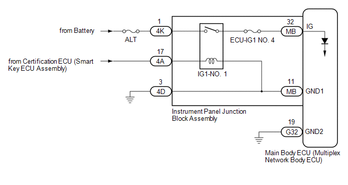
DESCRIPTION
This circuit detects the engine switch on (IG) or off condition, and sends it to the main body ECU (multiplex network body ECU).
WIRING DIAGRAM
CAUTION / NOTICE / HINT
NOTICE:
Click here 
Click here
PROCEDURE
|
1. | READ VALUE USING TECHSTREAM |
(a) Connect the Techstream to the DLC3.
(b) Turn the engine switch on (IG).
(c) Turn the Techstream on.
(d) Enter the following menus: Body Electrical / Main Body / Data List.
(e) Read the Data List according to the display on the Techstream.
Body Electrical > Main Body > Data List|
Tester Display | Measurement Item |
Range | Normal Condition |
Diagnostic Note |
|---|---|---|---|---|
|
IG SW | Engine switch on (IG) signal |
OFF or ON | OFF: Engine switch off ON: Engine switch on (IG) |
"OFF" is also displayed for this item when the engine switch is on (ACC). |
|
Tester Display |
|---|
| IG SW |
OK:
Normal conditions listed above are displayed.
| OK |  | PROCEED TO NEXT SUSPECTED AREA SHOWN IN PROBLEM SYMPTOMS TABLE |
|
| 2. |
CHECK HARNESS AND CONNECTOR (POWER SOURCE CIRCUIT) |
(a) Disconnect the 4K and 4D instrument panel junction block assembly connectors.
(b) Disconnect the G32 main body ECU (multiplex network body ECU) connector.
(c) Measure the voltage according to the value(s) in the table below.
Standard Voltage:
|
Tester Connection | Condition |
Specified Condition |
|---|---|---|
|
4K-1 - Body ground | Always |
11 to 14 V |
(d) Measure the resistance according to the value(s) in the table below.
Standard Resistance:
|
Tester Connection | Condition |
Specified Condition |
|---|---|---|
|
4D-3 - Body ground | Always |
Below 1 Ω |
|
G32-19 (GND2) - Body ground |
Always | Below 1 Ω |
| NG | | REPAIR OR REPLACE HARNESS OR CONNECTOR |
|
| 3. |
INSPECT INSTRUMENT PANEL JUNCTION BLOCK ASSEMBLY |
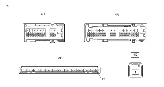
|
*a | Component without harness connected (Instrument Panel Junction Block Assembly) |
- | - |
(a) Remove the main body ECU (multiplex network body ECU) from the instrument panel junction block assembly.
Click here
(b) Measure the resistance according to the value(s) in the table below.
Standard Resistance:
|
Tester Connection | Condition |
Specified Condition |
|---|---|---|
|
4K-1 - MB-32 (IG) | Battery not connected to 4A-17 and 4D-3 |
10 kΩ or higher |
|
4K-1 - MB-32 (IG) | Battery positive (+) → 4A-17 Battery negative (-) → 4D-3 |
Below 1 Ω |
| OK | | REPLACE MAIN BODY ECU (MULTIPLEX NETWORK BODY ECU) |
| NG | | REPLACE INSTRUMENT PANEL JUNCTION BLOCK ASSEMBLY |
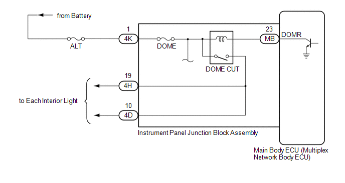
DESCRIPTION
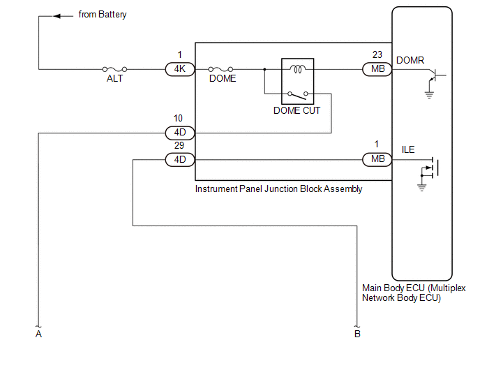
The main body ECU (multiplex network body ECU) controls operation of the DOME CUT relay in order to supply power to the interior lights. When the battery saving function operates while the interior lights are on, the main body ECU (multiplex network body ECU) opens the DOME CUT relay to turn off the lights.
WIRING DIAGRAM
CAUTION / NOTICE / HINT
NOTICE:
Click here 
PROCEDURE
|
1. | PERFORM ACTIVE TEST USING TECHSTREAM |
(a) Connect the Techstream to the DLC3.
(b) Turn the engine switch on (IG).
(c) Turn the Techstream on.
(d) Enter the following menus: Body Electrical / Main Body / Active Test.
(e) Perform the Active Test according to the display on the Techstream.
Body Electrical > Main Body > Active Test|
Tester Display | Measurement Item |
Control Range | Diagnostic Note |
|---|---|---|---|
|
Relay for Interior Light Auto Cut Function |
DOME CUT relay | OFF or ON |
When performing this Active Test, turn all the interior lights on.
|
|
Tester Display |
|---|
| Relay for Interior Light Auto Cut Function |
OK:
All of the interior lights turn off when ON is selected.
| OK |  | PROCEED TO NEXT SUSPECTED AREA SHOWN IN PROBLEM SYMPTOMS TABLE |
|
| 2. |
CHECK HARNESS AND CONNECTOR (POWER SOURCE - INSTRUMENT PANEL JUNCTION BLOCK ASSEMBLY) |
(a) Disconnect the 4K instrument panel junction block assembly connector.
(b) Measure the voltage according to the value(s) in the table below.
Standard Voltage:
|
Tester Connection | Condition |
Specified Condition |
|---|---|---|
|
4K-1 - Body ground | Always |
11 to 14 V |
| NG | | REPAIR OR REPLACE HARNESS OR CONNECTOR |
|
| 3. |
INSPECT INSTRUMENT PANEL JUNCTION BLOCK ASSEMBLY |
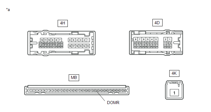
|
*a | Component without harness connected (Instrument Panel Junction Block Assembly) |
- | - |
(a) Remove the main body ECU (multiplex network body ECU) from the instrument panel junction block assembly.
Click here
(b) Measure the voltage according to the value(s) in the table below.
Standard Voltage:
|
Tester Connection | Condition |
Specified Condition |
|---|---|---|
|
4H-19 - Battery negative (-) |
Battery positive (+) → 4K-1 Battery negative (-) → MB-23 (DOMR) |
11 to 14 V |
|
4D-10 - Battery negative (-) |
Battery positive (+) → 4K-1 Battery negative (-) → MB-23 (DOMR) |
11 to 14 V |
(c) Measure the resistance according to the value(s) in the table below.
Standard Resistance:
|
Tester Connection | Condition |
Specified Condition |
|---|---|---|
|
4K-1 - 4H-19 | Always |
10 kΩ or higher |
|
4K-1 - 4D-10 | Always |
10 kΩ or higher |
| OK | | REPLACE MAIN BODY ECU (MULTIPLEX NETWORK BODY ECU) |
| NG | | REPLACE INSTRUMENT PANEL JUNCTION BLOCK ASSEMBLY |
DESCRIPTION
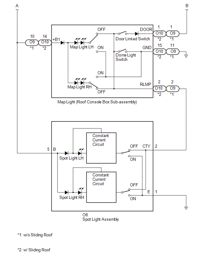
The main body ECU (multiplex network body ECU) controls the operation of the following lights:
WIRING DIAGRAM
CAUTION / NOTICE / HINT
NOTICE:
Click here 
HINT:
The DOME CUT relay supplies power to the interior lights. If all the lights that use power from the DOME CUT relay do not turn on, check the interior light auto cut circuit first.
Click here
PROCEDURE
| 1. |
PERFORM ACTIVE TEST USING TECHSTREAM |
(a) Connect the Techstream to the DLC3.
(b) Turn the engine switch on (IG).
(c) Turn the Techstream on.
(d) Enter the following menus: Body Electrical / Main Body / Active Test.
(e) Perform the Active Test according to the display on the Techstream.
Body Electrical > Main Body > Active Test|
Tester Display | Measurement Item |
Control Range | Diagnostic Note |
|---|---|---|---|
|
Illuminated Entry System |
Turns on the lights that are controlled by the illuminated entry system* |
OFF or ON | Perform the Active Test with the door linked switch of the map light (roof console box sub-assembly) on and switches of the spot light assembly LH and RH off. |
Click here
|
Tester Display |
|---|
| Illuminated Entry System |
OK:
All lights that are controlled by the illuminated entry system come on.
| OK |  | PROCEED TO NEXT SUSPECTED AREA SHOWN IN PROBLEM SYMPTOMS TABLE |
|
| 2. |
INSPECT MAP LIGHT (ROOF CONSOLE BOX SUB-ASSEMBLY) |
(a) Remove the map light (roof console box sub-assembly).
Click here
(b) Inspect the map light (roof console box sub-assembly).
Click here
| NG | | REPLACE MAP LIGHT (ROOF CONSOLE BOX SUB-ASSEMBLY) |
|
| 3. |
INSPECT SPOT LIGHT ASSEMBLY |
(a) Remove the spot light assembly.
Click here
(b) Inspect the spot light assembly.
Click here
| NG | | REPLACE SPOT LIGHT ASSEMBLY |
|
| 4. |
CHECK HARNESS AND CONNECTOR (MAP LIGHT (ROOF CONSOLE BOX SUB-ASSEMBLY) - SPOT LIGHT ASSEMBLY) |
(a) Measure the resistance according to the value(s) in the table below.
Standard Resistance:
w/o Sliding Roof|
Tester Connection | Condition |
Specified Condition |
|---|---|---|
|
O9-10 (+B1) - O8-5 (B) |
Always | Below 1 Ω |
|
O9-2 (RLMP) - O8-2 (CTY) |
Always | Below 1 Ω |
|
O9-10 (+B1) or O8-5 (B) - Body ground |
Always | 10 kΩ or higher |
|
O9-2 (RLMP) or O8-2 (CTY) - Body ground |
Always | 10 kΩ or higher |
|
Tester Connection | Condition |
Specified Condition |
|---|---|---|
|
O10-14 (+B1) - O8-5 (B) |
Always | Below 1 Ω |
|
O10-2 (RLMP) - O8-2 (CTY) |
Always | Below 1 Ω |
|
O10-14 (+B1) or O8-5 (B) - Body ground |
Always | 10 kΩ or higher |
|
O10-2 (RLMP) or O8-2 (CTY) - Body ground |
Always | 10 kΩ or higher |
| NG | | REPAIR OR REPLACE HARNESS OR CONNECTOR |
|
| 5. |
CHECK HARNESS AND CONNECTOR (INSTRUMENT PANEL JUNCTION BLOCK ASSEMBLY - MAP LIGHT (ROOF CONSOLE BOX SUB-ASSEMBLY)) |
(a) Disconnect the 4D instrument panel junction block assembly connector.
(b) Measure the resistance according to the value(s) in the table below.
Standard Resistance:
w/o Sliding Roof|
Tester Connection | Condition |
Specified Condition |
|---|---|---|
|
4D-10 - O9-10 (+B1) | Always |
Below 1 Ω |
|
4D-29 - O9-1 (DOOR) | Always |
Below 1 Ω |
|
4D-10 or O9-10 (+B1) - Body ground |
Always | 10 kΩ or higher |
|
4D-29 or O9-1 (DOOR) - Body ground |
Always | 10 kΩ or higher |
|
Tester Connection | Condition |
Specified Condition |
|---|---|---|
|
4D-10 - O10-14 (+B1) |
Always | Below 1 Ω |
|
4D-29 - O10-1 (DOOR) |
Always | Below 1 Ω |
|
4D-10 or O10-14 (+B1) - Body ground |
Always | 10 kΩ or higher |
|
4D-29 or O10-1 (DOOR) - Body ground |
Always | 10 kΩ or higher |
| NG | | REPAIR OR REPLACE HARNESS OR CONNECTOR |
|
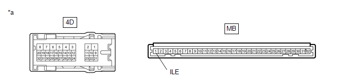
| 6. |
INSPECT INSTRUMENT PANEL JUNCTION BLOCK ASSEMBLY |
|
*a | Component without harness connected (Instrument Panel Junction Block Assembly) |
- | - |
(a) Remove the main body ECU (multiplex network body ECU) from the instrument panel junction block assembly.
Click here
(b) Measure the resistance according to the value(s) in the table below.
Standard Resistance:
|
Tester Connection | Condition |
Specified Condition |
|---|---|---|
|
4D-29 - MB-1 (ILE) | Always |
Below 1 Ω |
| OK | | REPLACE MAIN BODY ECU (MULTIPLEX NETWORK BODY ECU) |
| NG | | REPLACE INSTRUMENT PANEL JUNCTION BLOCK ASSEMBLY |
DESCRIPTION
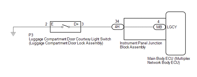
The main body ECU (multiplex network body ECU) receives a luggage compartment door open/closed signal from luggage compartment door courtesy light switch (luggage compartment door lock assembly).
WIRING DIAGRAM
CAUTION / NOTICE / HINT
NOTICE:
Before replacing the main body ECU (multiplex network body ECU), refer to Registration.
Click here 
PROCEDURE
| 1. |
READ VALUE USING TECHSTREAM |
(a) Connect the Techstream to the DLC3.
(b) Turn the engine switch on (IG).
(c) Turn the Techstream on.
(d) Enter the following menus: Body Electrical / Main Body / Data List.
(e) Read the Data List according to the display on the Techstream.
Body Electrical > Main Body > Data List|
Tester Display | Measurement Item |
Range | Normal Condition |
Diagnostic Note |
|---|---|---|---|---|
|
Luggage Courtesy SW | Luggage compartment door courtesy switch signal |
OFF or ON | OFF: Luggage compartment door closed ON: Luggage compartment door open |
- |
|
Tester Display |
|---|
| Luggage Courtesy SW |
OK:
Normal conditions listed above are displayed.
| OK |  | PROCEED TO NEXT SUSPECTED AREA SHOWN IN PROBLEM SYMPTOMS TABLE |
|
| 2. |
INSPECT LUGGAGE COMPARTMENT DOOR COURTESY LIGHT SWITCH (LUGGAGE COMPARTMENT DOOR LOCK ASSEMBLY) |
(a) Remove the luggage compartment door courtesy light switch (luggage compartment door lock assembly).
Click here
(b) Inspect the luggage compartment door courtesy light switch (luggage compartment door lock assembly).
Click here
| NG | | REPLACE LUGGAGE COMPARTMENT DOOR COURTESY LIGHT SWITCH (LUGGAGE COMPARTMENT DOOR LOCK ASSEMBLY) |
|
| 3. |
CHECK HARNESS AND CONNECTOR (LUGGAGE COMPARTMENT DOOR LOCK ASSEMBLY - INSTRUMENT PANEL JUNCTION BLOCK ASSEMBLY AND BODY GROUND) |
(a) Disconnect the 4H instrument panel junction block assembly connector.
(b) Measure the resistance according to the value (s) in the table below.
Standard Resistance:
|
Tester Connection | Condition |
Specified Condition |
|---|---|---|
|
P3-3 (D+) - 4H-34 | Always |
Below 1 Ω |
|
P3-3 (D+) or 4H-34 - Body ground |
Always | 10 kΩ or higher |
|
P3-2 (E) - Body ground |
Always | Below 1 Ω |
| NG | | REPAIR OR REPLACE HARNESS OR CONNECTOR |
|
| 4. |
INSPECT INSTRUMENT PANEL JUNCTION BLOCK ASSEMBLY |
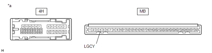
|
*a | Component without harness connected (Instrument Panel Junction Block Assembly) |
- | - |
(a) Remove the main body ECU (multiplex network body ECU) from the instrument panel junction block assembly.
Click here
(b) Measure the resistance according to the value(s) in the table below.
Standard Resistance:
|
Tester Connection | Condition |
Specified Condition |
|---|---|---|
|
4H-34 - MB-4 (LGCY) | Always |
Below 1 Ω |
| OK | | REPLACE MAIN BODY ECU (MULTIPLEX NETWORK BODY ECU) |
| NG | | REPLACE INSTRUMENT PANEL JUNCTION BLOCK ASSEMBLY |
OPERATION CHECK
INSPECT ILLUMINATED ENTRY SYSTEM OPERATION
NOTICE:
Perform this inspection with the customize parameters at the initial settings.
HINT:
Perform this inspection with the door linked switch of the map light (roof console box sub-assembly) on.
|
Control | Condition |
Lights that Operate |
|---|---|---|
|
Actuation Area-linked | With the engine switch off and all of the doors closed and locked, enter an exterior detection area while carrying an electrical key transmitter and check that the lights that operate turn on for approximately 15 seconds and then turn off. |
|
| Door Lock/Unlock-linked |
With the engine switch off and all of the doors closed and locked, unlock any door using an unlock operation (key-linked, wireless or entry unlock operation) and check that the lights that operate turn on for 15 seconds and then turn off. |
|
| Door Open/Close-linked |
With the engine switch off and all of the doors closed, open any door and check that the lights that operate turn on. While the lights that operate are on, close all of the doors and check that the lights that operate turn off after approximately 15 seconds. |
|
| With the engine switch off and all of the doors closed, open any door and check that the light that operates turns on. While the light that operates is on, close all of the doors and check that the light that operates turns off after approximately 40 seconds. |
Engine Switch Illumination | |
|
With the engine switch on (IG), open any door and check that the lights that operate turn on. While the lights that operate are on, close all of the doors and check that the lights that operate turn off. |
| |
| Engine Switch-linked |
Turn the engine switch from on (ACC) or on (IG) to off and check that the lights that operate turn on for approximately 15 seconds and then turn off. |
|
| Turn the engine switch from on (ACC) or on (IG) to off and check that the light that operates turns on for approximately 40 seconds and then turns off. |
Engine Switch Illumination |
INSPECT MOOD SWITCH OPERATION
(a) The operation and condition of this control are described below.
|
Control | Condition |
Lights that Operate |
|---|---|---|
| Mood Switch-linked* |
When the ambient illumination lights are on, and the mood switch is pressed, the ambient illumination lights dim. When the mood switch is pressed again, the lights fade out. |
|
INSPECT BATTERY SAVING CONTROL OPERATION
(a) The operations and conditions of this control are described below.
|
Control | Condition |
Lights that Operate |
|---|---|---|
| Battery Saving |
When 20 minutes elapse after the engine switch is turned from on (ACC) or on (IG) to off and the lights that operate remain on, the lights are turned off. HINT: Battery saving control is canceled when any of the following operations is performed before the lights are turned off by battery saving control. After the operation is performed, the lights remain on for another 20 minutes and then the lights are turned off.
|
|
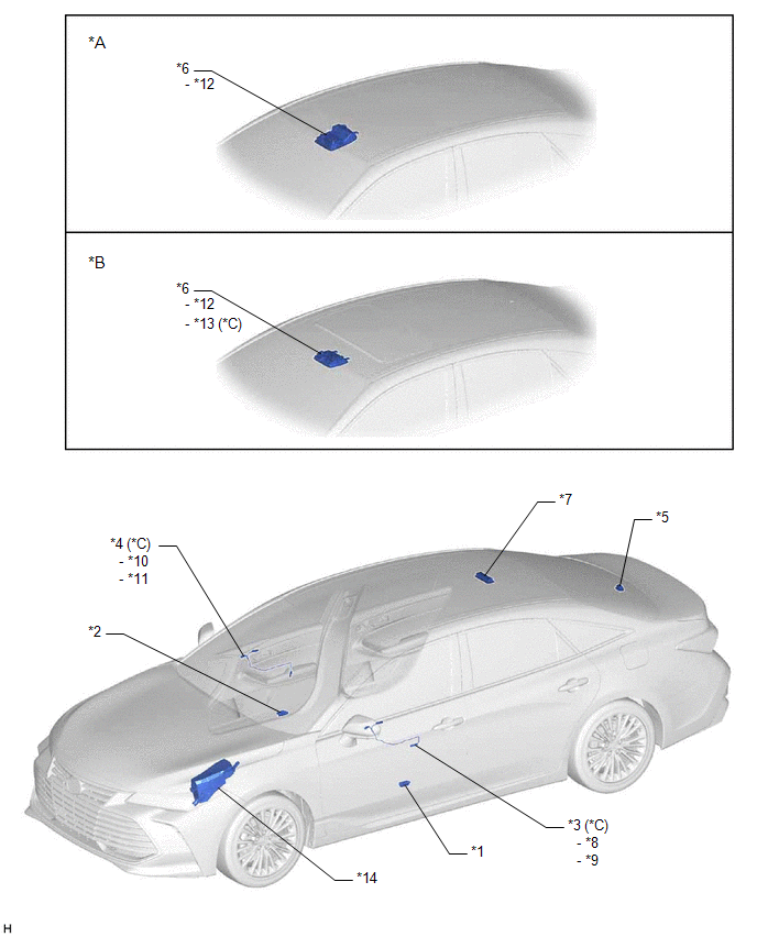
PARTS LOCATION
ILLUSTRATION
|
*A | w/o Sliding Roof |
*B | w/ Sliding Roof |
|
*C | w/ Mood Switch |
- | - |
|
*1 | COURTESY LIGHT ASSEMBLY LH |
*2 | COURTESY LIGHT ASSEMBLY RH |
|
*3 | FRONT DOOR INSIDE HANDLE ILLUMINATION LIGHT ASSEMBLY LH |
*4 | FRONT DOOR INSIDE HANDLE ILLUMINATION LIGHT ASSEMBLY RH |
|
*5 | NO. 1 LUGGAGE COMPARTMENT LIGHT ASSEMBLY |
*6 | ROOF CONSOLE BOX SUB-ASSEMBLY |
|
*7 | SPOT LIGHT ASSEMBLY |
*8 | DOOR INSIDE HANDLE ILLUMINATION LIGHT LH |
|
*9 | DOOR AMBIENT ILLUMINATION LIGHT LH |
*10 | DOOR INSIDE HANDLE ILLUMINATION LIGHT RH |
|
*11 | DOOR AMBIENT ILLUMINATION LIGHT RH |
*12 | MAP LIGHT |
|
*13 | MOOD SWITCH |
*14 | NO. 1 ENGINE ROOM RELAY BLOCK AND NO. 1 JUNCTION BLOCK ASSEMBLY - ALT FUSE |
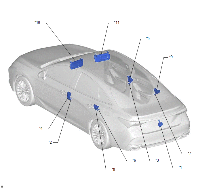
ILLUSTRATION
|
*1 | LUGGAGE COMPARTMENT DOOR COURTESY LIGHT SWITCH (LUGGAGE COMPARTMENT DOOR LOCK ASSEMBLY) |
*2 | FRONT DOOR COURTESY LIGHT SWITCH ASSEMBLY (for LH) |
|
*3 | FRONT DOOR COURTESY LIGHT SWITCH ASSEMBLY (for RH) |
*4 | FRONT DOOR LOCK WITH MOTOR ASSEMBLY LH |
|
*5 | FRONT DOOR LOCK WITH MOTOR ASSEMBLY RH |
*6 | REAR DOOR COURTESY LIGHT SWITCH ASSEMBLY (for LH) |
|
*7 | REAR DOOR COURTESY LIGHT SWITCH ASSEMBLY (for RH) |
*8 | REAR DOOR LOCK WITH MOTOR ASSEMBLY LH |
|
*9 | REAR DOOR LOCK WITH MOTOR ASSEMBLY RH |
*10 | VANITY LIGHT (VISOR ASSEMBLY LH) |
|
*11 | VANITY LIGHT (VISOR ASSEMBLY RH) |
- | - |
ILLUSTRATION
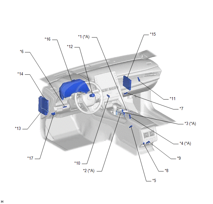
|
*A | w/ Mood Switch |
- | - |
|
*1 | CENTER CONSOLE LIGHT (for Passenger Side) (NO. 2 INTERIOR ILLUMINATION LIGHT SUB-ASSEMBLY) |
*2 | CENTER CONSOLE LIGHT (for Driver Side) (NO. 3 INTERIOR ILLUMINATION LIGHT SUB-ASSEMBLY) |
|
*3 | CUP HOLDER LIGHT (for Front Side) (NO. 4 INTERIOR ILLUMINATION LIGHT SUB-ASSEMBLY) |
*4 | CUP HOLDER LIGHT (for Rear Side) (NO. 4 INTERIOR ILLUMINATION LIGHT SUB-ASSEMBLY) |
|
*5 | CONSOLE BOX LIGHT (NO. 5 INTERIOR ILLUMINATION LIGHT SUB-ASSEMBLY) |
*6 | FRONT FOOTWELL LIGHT LH (NO. 1 INTERIOR ILLUMINATION LIGHT ASSEMBLY) |
|
*7 | FRONT FOOTWELL LIGHT RH (NO. 1 INTERIOR ILLUMINATION LIGHT ASSEMBLY) |
*8 | REAR FOOTWELL LIGHT LH (NO. 6 INTERIOR ILLUMINATION LIGHT SUB-ASSEMBLY) |
|
*9 | REAR FOOTWELL LIGHT RH (NO. 6 INTERIOR ILLUMINATION LIGHT SUB-ASSEMBLY) |
*10 | FRONT CONSOLE LIGHT (INTERIOR ILLUMINATION LIGHT SUB-ASSEMBLY) |
|
*11 | GLOVE BOX LIGHT ASSEMBLY |
*12 | ENGINE SWITCH |
|
*13 | INSTRUMENT PANEL JUNCTION BLOCK ASSEMBLY - ECU-ACC FUSE - ECU-IG1 NO. 4 FUSE - DOME FUSE - ECU-DCC NO. 2 FUSE - ACC RELAY - IG1-NO. 1 RELAY - DOME CUT RELAY |
*14 | MAIN BODY ECU (MULTIPLEX NETWORK BODY ECU) |
|
*15 | CERTIFICATION ECU (SMART KEY ECU ASSEMBLY) |
*16 | COMBINATION METER ASSEMBLY |
|
*17 | DLC3 |
- | - |
PRECAUTION
PRECAUTION FOR DISCONNECTING CABLE FROM NEGATIVE BATTERY TERMINAL
NOTICE:
When disconnecting the cable from the negative (-) battery terminal, initialize the following systems after the cable is reconnected.
|
System Name | See Procedure |
|---|---|
|
Lane Departure Alert System (w/ Steering Control) |
|
|
Pre-collision System | |
|
Intelligent Clearance Sonar System | |
|
Lighting System (for Gasoline Model with Cornering Light) | |
|
Parking Assist Monitor System | |
|
Panoramic View Monitor System |
PROBLEM SYMPTOMS TABLE
NOTICE:
Before replacing the main body ECU (multiplex network body ECU) or certification ECU (smart key ECU assembly), refer to Registration.

HINT:
|
Symptom | Suspected Area |
Link |
|---|---|---|
| Map light LH or map light RH does not illuminate (Other interior lights are normal) |
Map light (Roof console box sub-assembly) |
|
|
Map light LH and map light RH do not illuminate (Other interior lights are normal) |
Map light (Roof console box sub-assembly) |
|
|
Harness or connector |
- | |
| Switch illumination or shift lever illumination does not illuminate (Other interior lights are normal) |
Map light (Roof console box sub-assembly) |
|
|
Switch illumination and shift lever illumination do not illuminate (Other interior lights are normal) |
Map light (Roof console box sub-assembly) |
|
|
Harness or connector |
- |
|
Symptom | Suspected Area |
Link |
|---|---|---|
| Spot light LH or spot light RH does not illuminate (Other interior lights are normal) |
Spot light assembly |
|
|
Spot light LH and spot light RH do not illuminate (Other interior lights are normal) |
Spot light assembly |
|
|
Harness or connector |
- |
|
Symptom | Suspected Area |
Link |
|---|---|---|
|
Vanity light LH does not illuminate |
Bulb |
|
|
Visor assembly LH |
| |
|
Harness or connector |
- | |
|
Vanity light RH does not illuminate |
Bulb |
|
|
Visor assembly RH |
| |
|
Harness or connector |
- |
|
Symptom | Suspected Area |
Link |
|---|---|---|
|
Courtesy light LH does not illuminate |
Bulb |
|
|
Courtesy light assembly LH |
| |
|
Front door courtesy switch circuit |
| |
|
Harness or connector |
- | |
| Main body ECU (Multiplex network body ECU) |
| |
|
Courtesy light RH does not illuminate |
Bulb |
|
|
Courtesy light assembly RH |
| |
|
Front door courtesy switch circuit |
| |
|
Harness or connector |
- | |
| Main body ECU (Multiplex network body ECU) |
|
|
Symptom | Suspected Area |
Link |
|---|---|---|
|
Glove box light does not illuminate |
Glove box light assembly |
|
|
Harness or connector |
- |
|
Symptom | Suspected Area |
Link |
|---|---|---|
|
Console box light does not illuminate |
Console box light (No. 5 interior illumination light sub-assembly) |
|
|
Harness or connector |
- |
|
Symptom | Suspected Area |
Link |
|---|---|---|
|
Front footwell light LH does not illuminate |
Front footwell light LH (No. 1 interior illumination light sub-assembly) |
|
|
Harness or connector |
- | |
|
Front footwell light RH does not illuminate |
Front footwell light RH (No. 1 interior illumination light sub-assembly) |
|
|
Harness or connector |
- | |
|
Rear footwell light LH does not illuminate. |
Rear footwell light LH (No. 6 interior illumination light sub-assembly) |
|
|
Harness or connector |
- | |
|
Rear footwell light RH does not illuminate |
Rear footwell light RH (No. 6 interior illumination light sub-assembly) |
|
|
Harness or connector |
- | |
|
Front console light does not illuminate |
Front console light (interior illumination light sub-assembly) |
|
|
Harness or connector |
- | |
|
All footwell lights and front console light do not illuminate |
Harness or connector |
- |
| Combination meter assembly |
|
|
Symptom | Suspected Area |
Link |
|---|---|---|
| Front door inside handle illumination light LH does not illuminate |
Ambient illumination light circuit |
|
|
Front door inside handle illumination light RH does not illuminate |
Ambient illumination light circuit |
|
|
Console light (for passenger side) does not illuminate |
Ambient illumination light circuit |
|
|
Console light (for driver side) does not illuminate |
Ambient illumination light circuit |
|
|
Cup holder light (for front side) does not illuminate |
Ambient illumination light circuit |
|
|
Cup holder light (for rear side) does not illuminate |
Ambient illumination light circuit |
|
|
All ambient illumination lights do not illuminate |
Ambient illumination light circuit |
|
|
Ambient light switch circuit |
| |
|
Instrument panel junction block assembly |
| |
|
Main body ECU (Multiplex network body ECU) |
|
|
Symptom | Suspected Area |
Link |
|---|---|---|
|
Luggage compartment light does not illuminate (Other interior lights are normal) |
Bulb |
|
|
No. 1 luggage compartment light assembly |
| |
|
Luggage compartment door courtesy switch circuit |
| |
|
Harness or connector |
- | |
| Main body ECU (Multiplex network body ECU) |
|
|
Symptom | Suspected Area |
Link |
|---|---|---|
|
All the interior lights that receive power via the DOME CUT relay do not illuminate |
Interior light auto cut circuit |
|
|
Main body ECU (Multiplex network body ECU) |
|
|
Symptom | Suspected Area |
Link |
|---|---|---|
|
All illuminated entry system control functions do not operate under any condition |
Check customize parameters (Interior Light Control) |
|
|
Interior light auto cut circuit |
| |
|
Interior light circuit |
| |
|
Main body ECU (Multiplex network body ECU) |
| |
|
Actuation area-linked control function does not operate when registered key is brought into any exterior detection area |
Check customize parameters (Room Light when Aprchd) |
|
|
CAN communication system |
| |
|
Smart key system (for Entry Function) |
| |
|
Main body ECU (Multiplex network body ECU) |
| |
|
Door lock/unlock-linked control function does not operate when doors are locked/unlocked |
Check customize parameters (I/L ON W/Door Key Unlock) |
|
|
Door unlock detection switch circuit |
| |
|
Main body ECU (Multiplex network body ECU) |
| |
|
Door open/close-linked control function does not operate when doors are opened/closed |
Front door courtesy switch circuit |
|
|
Rear door courtesy switch circuit |
| |
|
Main body ECU (Multiplex network body ECU) |
| |
|
Engine switch-linked control function does not operate when engine switch is operated |
Check customize parameters (I/L when ACC OFF) |
|
|
IG signal circuit |
| |
|
ACC signal circuit |
| |
|
Main body ECU (Multiplex network body ECU) |
| |
|
Engine switch illumination does not illuminate |
CAN communication system |
|
|
Engine switch illumination circuit |
| |
|
Certification ECU (Smart key ECU assembly) |
| |
|
Ambient light dimmer control does not operate with mood switch operation |
Ambient light switch circuit |
|
|
Main body ECU (Multiplex network body ECU) |
|
|
Symptom | Suspected Area |
Link |
|---|---|---|
|
Battery saving function does not operate |
IG signal circuit |
|
|
ACC signal circuit |
| |
|
Front door courtesy switch circuit |
| |
|
Rear door courtesy switch circuit |
| |
|
Luggage compartment door courtesy switch circuit |
| |
|
Door unlock detection switch circuit |
| |
|
Interior light auto cut circuit |
| |
|
Main body ECU (Multiplex network body ECU) |
|
DESCRIPTION
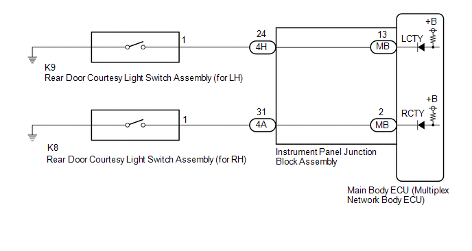
The main body ECU (multiplex network body ECU) detects the condition of the rear door courtesy light switch assembly.
WIRING DIAGRAM
CAUTION / NOTICE / HINT
NOTICE:
Before replacing the main body ECU (multiplex network body ECU), refer to Registration.
Click here 
PROCEDURE
| 1. |
READ VALUE USING TECHSTREAM |
(a) Connect the Techstream to the DLC3.
(b) Turn the engine switch on (IG).
(c) Turn the Techstream on.
(d) Enter the following menus: Body Electrical / Main Body / Data List.
(e) Read the Data List according to the display on the Techstream.
Body Electrical > Main Body > Data List|
Tester Display | Measurement Item |
Range | Normal Condition |
Diagnostic Note |
|---|---|---|---|---|
|
RR Door Courtesy SW | Rear door courtesy light switch assembly (for RH) signal |
OFF or ON | OFF: Rear door RH closed ON: Rear door RH open |
- |
| RL Door Courtesy SW |
Rear door courtesy light switch assembly (for LH) signal |
OFF or ON | OFF: Rear door LH closed ON: Rear door LH open |
- |
|
Tester Display |
|---|
| RR Door Courtesy SW |
|
RL Door Courtesy SW |
OK:
Normal conditions listed above are displayed.
|
Result | Proceed to |
|---|---|
|
OK | A |
|
NG ("RR Door Courtesy SW" is not normal) |
B |
| NG ("RL Door Courtesy SW" is not normal) |
C |
| A |
 | PROCEED TO NEXT SUSPECTED AREA SHOWN IN PROBLEM SYMPTOMS TABLE |
| C |
| GO TO STEP 5 |
|
| 2. |
INSPECT REAR DOOR COURTESY LIGHT SWITCH ASSEMBLY (for RH) |
(a) Remove the rear door courtesy light switch assembly (for RH).
Click here
(b) Inspect the rear door courtesy light switch assembly (for RH).
Click here
| NG | | REPLACE REAR DOOR COURTESY LIGHT SWITCH ASSEMBLY (for RH) |
|
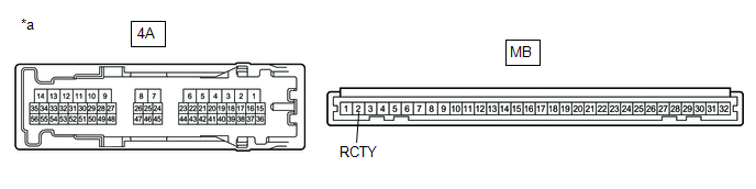
| 3. |
CHECK HARNESS AND CONNECTOR (REAR DOOR COURTESY LIGHT SWITCH ASSEMBLY (for RH) - INSTRUMENT PANEL JUNCTION BLOCK ASSEMBLY) |
(a) Disconnect the 4A instrument panel junction block assembly connector.
(b) Measure the resistance according to the value(s) in the table below.
Standard Resistance:
|
Tester Connection | Condition |
Specified Condition |
|---|---|---|
|
K8-1 - 4A-31 | Always |
Below 1 Ω |
|
K8-1 or 4A-31 - Body ground |
Always | 10 kΩ or higher |
| NG | | REPAIR OR REPLACE HARNESS OR CONNECTOR |
|
| 4. |
INSPECT INSTRUMENT PANEL JUNCTION BLOCK ASSEMBLY |
|
*a | Component without harness connected (Instrument Panel Junction Block Assembly) |
- | - |
(a) Remove the main body ECU (multiplex network body ECU) from the instrument panel junction block assembly.
Click here
(b) Measure the resistance according to the value(s) in the table below.
Standard Resistance:
|
Tester Connection | Condition |
Specified Condition |
|---|---|---|
|
4A-31 - MB-2 (RCTY) | Always |
Below 1 Ω |
| OK | | REPLACE MAIN BODY ECU (MULTIPLEX NETWORK BODY ECU) |
| NG | | REPLACE INSTRUMENT PANEL JUNCTION BLOCK ASSEMBLY |
| 5. |
INSPECT REAR DOOR COURTESY LIGHT SWITCH ASSEMBLY (for LH) |
(a) Remove the rear door courtesy light switch assembly (for LH).
Click here
(b) Inspect the rear door courtesy light switch assembly (for LH).
Click here
| NG | | REPLACE REAR DOOR COURTESY LIGHT SWITCH ASSEMBLY (for LH) |
|
| 6. |
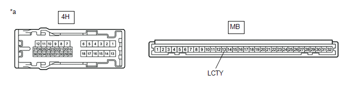
CHECK HARNESS AND CONNECTOR (REAR DOOR COURTESY LIGHT SWITCH ASSEMBLY (for LH) - INSTRUMENT PANEL JUNCTION BLOCK ASSEMBLY) |
(a) Disconnect the 4H instrument panel junction block assembly connector.
(b) Measure the resistance according to the value(s) in the table below.
Standard Resistance:
|
Tester Connection | Condition |
Specified Condition |
|---|---|---|
|
K9-1 - 4H-24 | Always |
Below 1 Ω |
|
K9-1 or 4H-24 - Body ground |
Always | 10 kΩ or higher |
| NG | | REPAIR OR REPLACE HARNESS OR CONNECTOR |
|
| 7. |
INSPECT INSTRUMENT PANEL JUNCTION BLOCK ASSEMBLY |
|
*a | Component without harness connected (Instrument Panel Junction Block Assembly) |
- | - |
(a) Remove the main body ECU (multiplex network body ECU) from the instrument panel junction block assembly.
Click here
(b) Measure the resistance according to the value(s) in the table below.
Standard Resistance:
|
Tester Connection | Condition |
Specified Condition |
|---|---|---|
|
4H-24 - MB-13 (LCTY) |
Always | Below 1 Ω |
| OK | | REPLACE MAIN BODY ECU (MULTIPLEX NETWORK BODY ECU) |
| NG | | REPLACE INSTRUMENT PANEL JUNCTION BLOCK ASSEMBLY |
SYSTEM DESCRIPTION
ILLUMINATED ENTRY SYSTEM
(a) The illuminated entry system has the following control functions:
|
Control | Outline |
Lights that Operate |
|---|---|---|
| Actuation Area-linked |
When a registered key is brought within any vehicle exterior detection area around the doors, the lights that operate turn on. |
|
| Door Lock/Unlock-linked |
When any door is unlocked, the lights that operate turn on. |
|
| When all doors are locked, the lights that operate turn off. | ||
|
Door Open/Close-linked | When any door is opened, the lights that operate turn on. |
|
| When all doors are closed, the lights that operate turn off. | ||
|
Engine Switch-linked | When the engine switch is turned from on (ACC) or on (IG) to off, the lights that operate turn on. |
|
| When the engine switch is turned from off to on (ACC) or on (IG), the lights that operate turn off. |
| |
| Delay |
When approximately 15 seconds elapse after any of the following conditions is met, the lights that operate turn off:
|
|
| When approximately 40 seconds elapse after any of the following conditions is met, the lights that operate turn off:
| Engine Switch Illumination |
MOOD SWITCH
(a) The mood switch function has the following control functions:
|
Control | Condition |
Lights that Operate |
|---|---|---|
| Mood Switch-linked* |
When the ambient illumination lights are on, and the mood switch is pressed, the ambient illumination lights dim. When the mood switch is pressed again, the lights fade out. |
|
BATTERY SAVING CONTROL SYSTEM
(a) The battery saving function has the following control functions:
|
Control | Condition |
Lights that Operate |
|---|---|---|
| Battery Saving |
When 20 minutes elapse after the engine switch is turned from on (ACC) or on (IG) to off and the lights that operate remain on, the lights are turned off. HINT: Battery saving control is canceled when any of the following operations is performed before the lights are turned off by battery saving control. After the operation is performed, the lights remain on for another 20 minutes and then the lights are turned off.
|
|
SYSTEM DIAGRAM
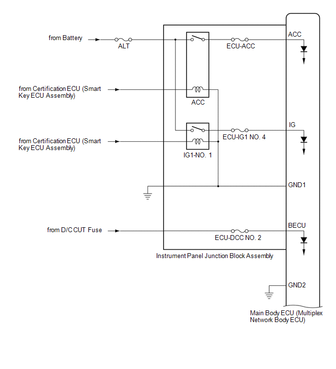
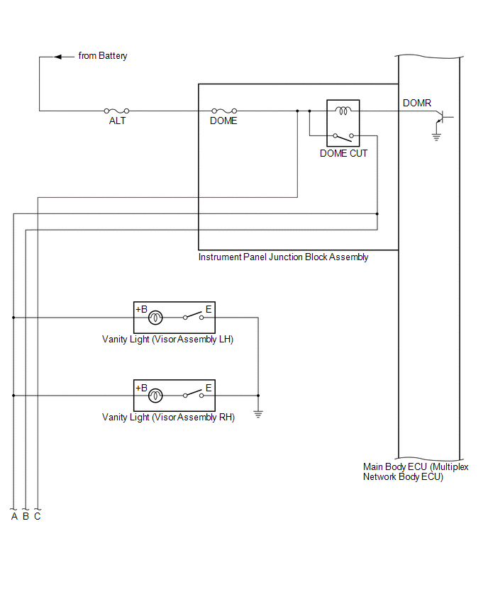
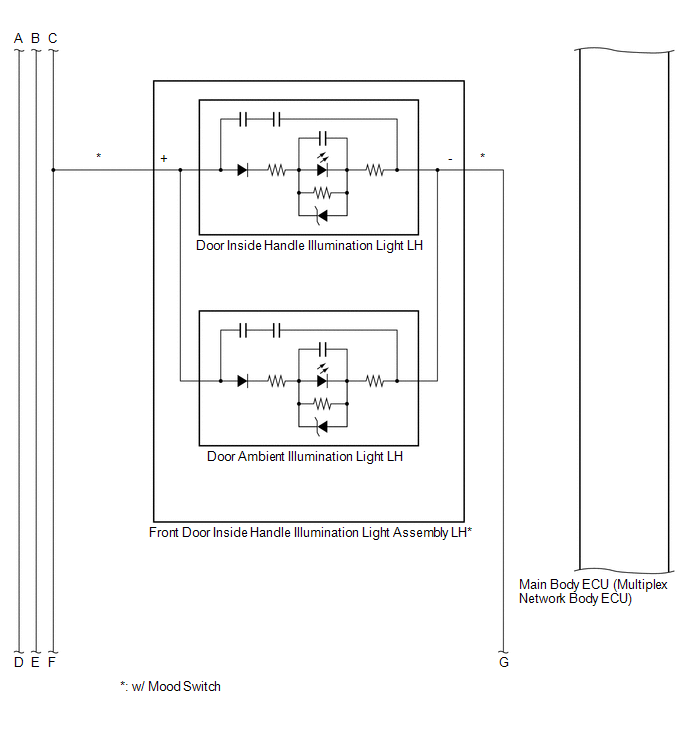
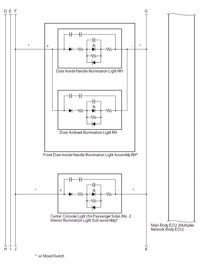
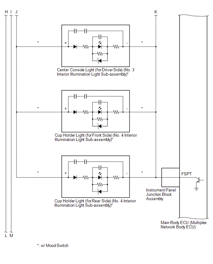
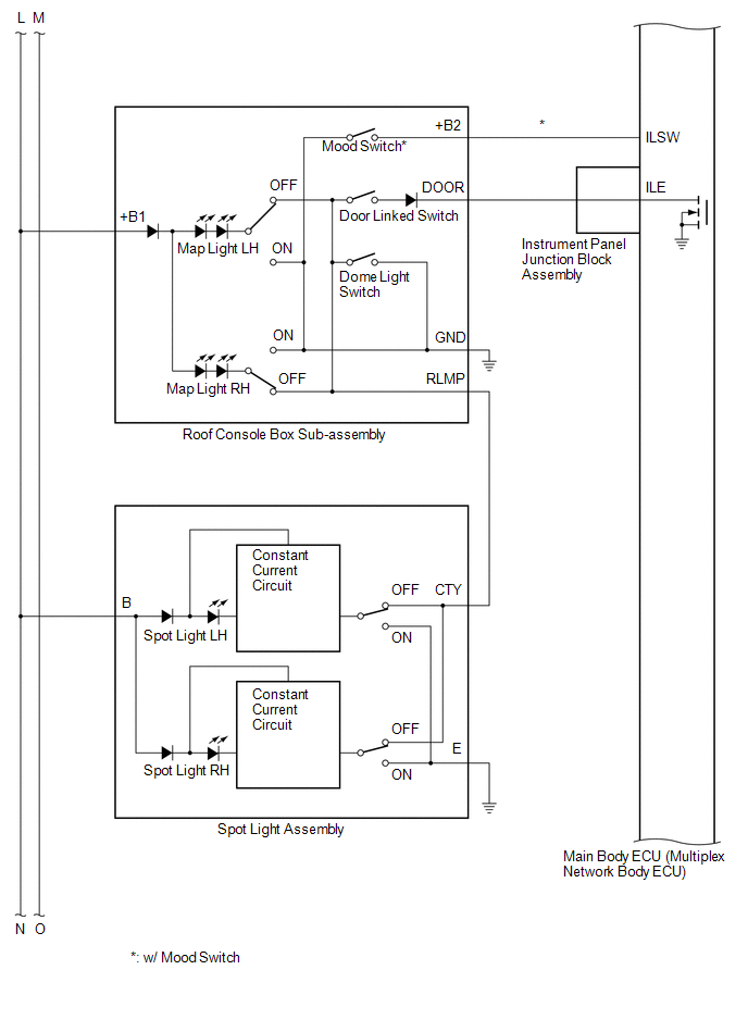
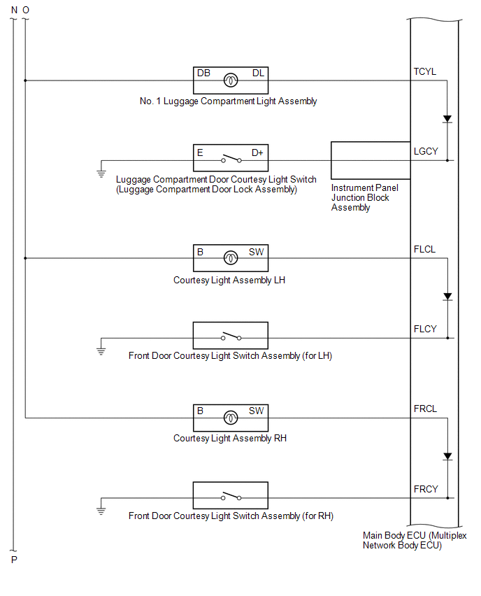
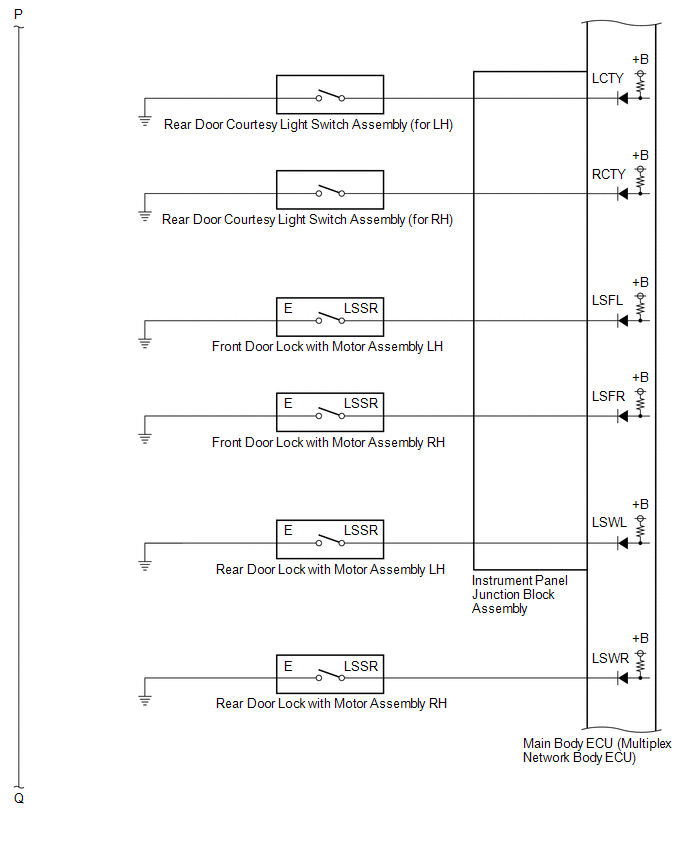
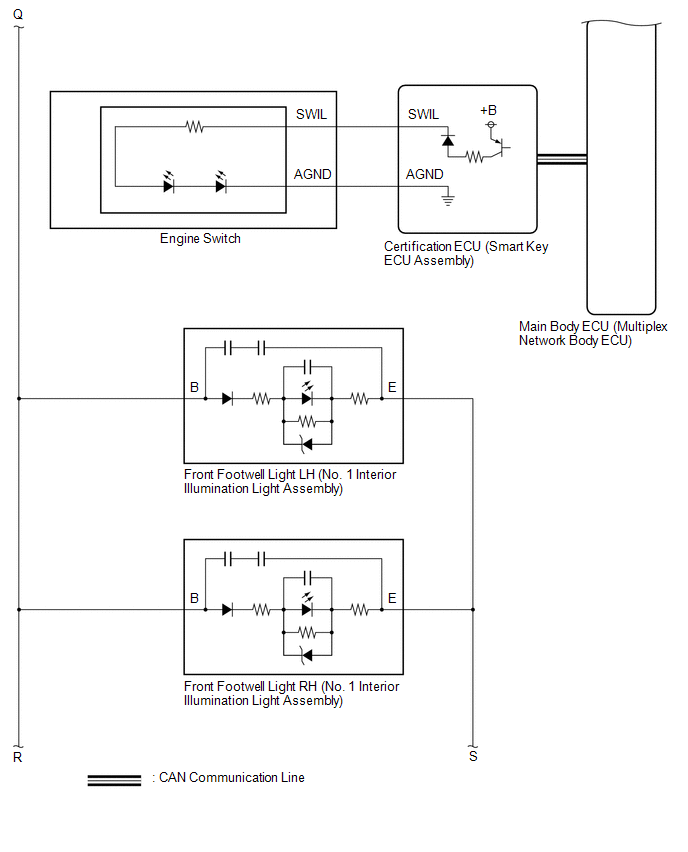
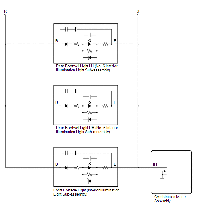
TERMINALS OF ECU
CHECK MAIN BODY ECU (MULTIPLEX NETWORK BODY ECU) AND INSTRUMENT PANEL JUNCTION BLOCK ASSEMBLY

(a) Disconnect the instrument panel junction block assembly and main body ECU (multiplex network body ECU) connectors.
(b) Measure the voltage and resistance according to the value(s) in the table below.
|
Terminal No. (Symbol) | Wiring Color |
Terminal Description | Condition |
Specified Condition |
|---|---|---|---|---|
|
4D-3 - Body ground | LA - Body ground |
Ground | Always |
Below 1 Ω |
|
4F-1 - Body ground | LG - Body ground |
Battery power supply | Always |
11 to 14 V |
|
4K-1 - Body ground | B - Body ground*1 W - Body ground*2 | Battery power supply |
Always | 11 to 14 V |
|
G32-19 (GND2) - Body ground |
W-B - Body ground | Ground |
Always | Below 1 Ω |
(c) Connect the instrument panel junction block assembly and main body ECU (multiplex network body ECU) connectors.
(d) Measure the voltage and check for pulses according to the value(s) in the table below.
|
Terminal No. (Symbol) | Wiring Color |
Terminal Description | Condition |
Specified Condition |
|---|---|---|---|---|
|
4A-17 - Body ground |
R - Body ground | IG power supply |
Engine switch on (IG) |
11 to 14 V |
| Engine switch off |
Below 1 V | |||
|
4A-30 - Body ground |
LG - Body ground |
ACC power supply | Engine switch on (ACC) |
11 to 14 V |
| Engine switch off |
Below 1 V | |||
|
4A-31 - Body ground |
V - Body ground |
Rear door courtesy light switch assembly (for RH) input |
Rear door RH open | Below 1 V |
|
Rear door RH closed | 11 to 14 V | |||
|
4A-36 - Body ground* |
SB - Body ground |
Front door inside handle illumination light assembly LH and RH, center console light (for passenger side) (No. 2 interior illumination light sub-assembly), center console light (for driver side (No. 3 interior illumination light sub-assembly) and cup holder light (for front side and rear side) (No. 4 interior illumination light sub-assembly) drive output | Front door inside handle illumination light assembly LH and RH, center console light (for passenger side) (No. 2 interior illumination light sub-assembly), center console light (for driver side (No. 3 interior illumination light sub-assembly) and cup holder light (for front side and rear side) (No. 4 interior illumination light sub-assembly) off |
11 to 14 V |
| Front door inside handle illumination light assembly LH and RH, center console light (for passenger side) (No. 2 interior illumination light sub-assembly), center console light (for driver side (No. 3 interior illumination light sub-assembly) and cup holder light (for front side and rear side) (No. 4 interior illumination light sub-assembly) dimmer control operating (dimming) | Pulse generation | |||
|
Front door inside handle illumination light assembly LH and RH, center console light (for passenger side) (No. 2 interior illumination light sub-assembly), center console light (for driver side (No. 3 interior illumination light sub-assembly) and cup holder light (for front side and rear side) (No. 4 interior illumination light sub-assembly) at full brightness | Below 2.2 V | |||
|
4D-10 - Body ground |
R - Body ground |
Roof console box sub-assembly, spot light assembly, vanity light (visor assembly LH), vanity light (visor assembly RH), front footwell light LH and RH (No. 1 interior illumination light assembly), rear footwell light LH and RH (No. 6 interior illumination light sub-assembly) and front console light (interior illumination light sub-assembly) power supply |
DOME CUT relay on | 11 to 14 V |
|
DOME CUT relay off | Below 1 V | |||
|
4D-12 - Body ground |
GR - Body ground |
Front door unlock detection switch RH input |
Front door RH locked |
11 to 14 V |
| Front door RH unlocked |
Below 1 V | |||
|
4D-13 - Body ground |
W - Body ground |
Front door unlock detection switch LH input |
Front door LH locked |
11 to 14 V |
| Front door LH unlocked |
Below 1 V | |||
|
4D-14 - Body ground |
GR - Body ground |
Rear door unlock detection switch LH input |
Rear door LH locked | 11 to 14 V |
|
Rear door LH unlocked |
Below 1 V | |||
|
4D-24 - Body ground* |
LG - Body ground | Front door inside handle illumination light assembly LH and RH, center console light (for passenger side) (No. 2 interior illumination light sub-assembly), center console light (for driver side) (No. 3 interior illumination light sub-assembly) and cup holder light (for front side and rear side) (No. 4 interior illumination light sub-assembly) power supply | Always |
11 to 14 V |
|
4D-29 - Body ground |
LA-G - Body ground | Illuminated entry system drive output |
Map light LH and map light RH (map light (roof console box sub-assembly)) off (when operated by illuminated entry system) |
11 to 14 V |
| Map light LH and map light RH (map light (roof console box sub-assembly)) on (when operated by illuminated entry system) |
Below 1 V | |||
|
4H-19 - Body ground |
LA-B - Body ground |
No. 1 luggage compartment light assembly and courtesy light assembly LH and RH power supply |
DOME CUT relay on | 11 to 14 V |
|
DOME CUT relay off | Below 1 V | |||
|
4H-24 - Body ground |
G - Body ground | Rear door courtesy light switch assembly (for LH) input |
Rear door LH open | Below 1 V |
|
Rear door LH closed | 11 to 14 V | |||
|
4H-34 - Body ground |
LA-GR - Body ground |
Luggage compartment door courtesy light switch (luggage compartment door lock assembly) input |
Luggage compartment door open |
Below 1 V |
| Luggage compartment door closed |
11 to 14 V | |||
|
G32-20 (LSWR) - Body ground |
L - Body ground |
Rear door unlock detection switch RH input |
Rear door RH locked | 11 to 14 V |
|
Rear door RH unlocked |
Below 1 V | |||
|
G33-1 (FLCY) - Body ground |
W - Body ground | Front door courtesy light switch assembly (for LH) input |
Front door LH open | Below 1 V |
|
Front door LH closed |
11 to 14 V | |||
|
G33-2 (FLCL) - Body ground |
G - Body ground |
Courtesy light assembly LH drive output |
Courtesy light assembly LH off |
11 to 14 V |
| Courtesy light assembly LH on |
Below 1 V | |||
|
G33-3 (FRCL) - Body ground |
L - Body ground |
Courtesy light assembly RH drive output |
Courtesy light assembly RH off |
11 to 14 V |
| Courtesy light assembly RH on |
Below 1 V | |||
|
G33-6 (FRCY) - Body ground |
BE - Body ground |
Front door courtesy light switch assembly (for RH) input |
Front door RH open | Below 1 V |
|
Front door RH closed |
11 to 14 V | |||
|
G33-14 (ILSW) - Body ground* |
W - Body ground |
Mood switch signal input |
Mood switch off | 11 to 14 V |
|
Mood switch on | Below 1 V | |||
|
G33-20 (TCYL) - Body ground |
GR - Body ground |
No. 1 luggage compartment light assembly drive output |
No. 1 luggage compartment light assembly off |
11 to 14 V |
| No. 1 luggage compartment light assembly on |
Below 1 V |
CHECK CERTIFICATION ECU (SMART KEY ECU ASSEMBLY)

(a) Measure the voltage according to the value(s) in the table below.
|
Terminal No. (Symbol) | Wiring Color |
Terminal Description | Condition |
Specified Condition |
|---|---|---|---|---|
|
G40-10 (SWIL) - G40-11 (AGND) |
W - BE | Engine switch illumination drive output |
Engine switch illumination on |
11 to 14 V |
| Engine switch illumination off |
Below 1 V |
Toyota Avalon (XX50) 2019-2022 Service & Repair Manual > Navigation System(for Gasoline Model): Precaution. Problem Symptoms Table. Radio Broadcast cannot be Received or Poor Reception
Precaution PRECAUTION PRECAUTION FOR DISCONNECTING CABLE FROM NEGATIVE BATTERY TERMINAL NOTICE: After the engine switch is turned off, the radio and display receiver assembly records various types of memory and settings. As a result, after turning the engine switch off, make sure to wait at least 85 ...


