COMPONENTS
ILLUSTRATION
|
*A | for HV Model |
- | - |
|
*1 | LUGGAGE TRIM SERVICE HOLE COVER |
- | - |
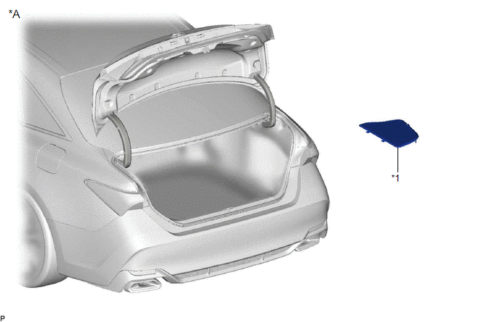
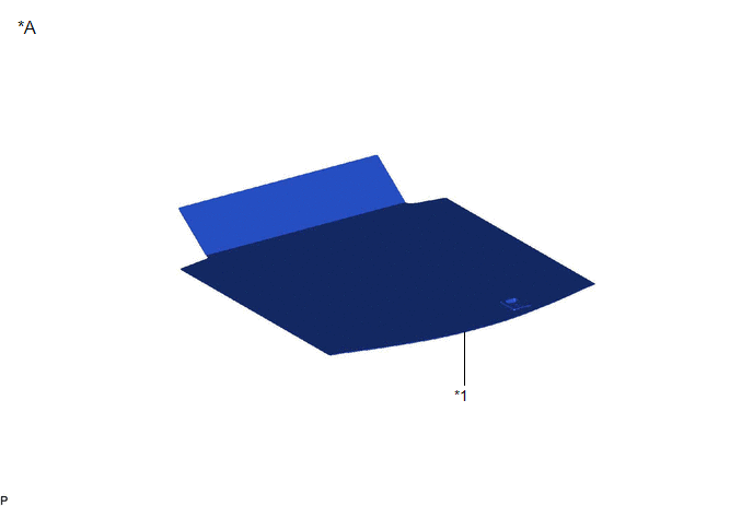
ILLUSTRATION
|
*A | w/ Seat Heater System |
- | - |
|
*1 | SPARE WHEEL COVER ASSEMBLY |
- | - |
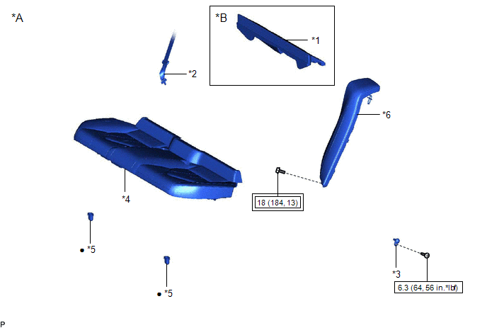
ILLUSTRATION
|
*A | for Gasoline Model |
*B | w/ Seat Heater System |
|
*1 | LUGGAGE COMPARTMENT INNER TRIM PAD |
*2 | REAR CENTER SEAT OUTER BELT ASSEMBLY |
|
*3 | REAR DOOR COURTESY LIGHT SWITCH ASSEMBLY |
*4 | REAR SEAT CUSHION ASSEMBLY |
|
*5 | REAR SEAT CUSHION LOCK HOOK |
*6 | REAR SIDE SEATBACK ASSEMBLY |
 |
Tightening torque for "Major areas involving basic vehicle performance such as moving/turning/stopping": N*m (kgf*cm, ft.*lbf) |
 |
N*m (kgf*cm, ft.*lbf): Specified torque |
|
● | Non-reusable part |
- | - |
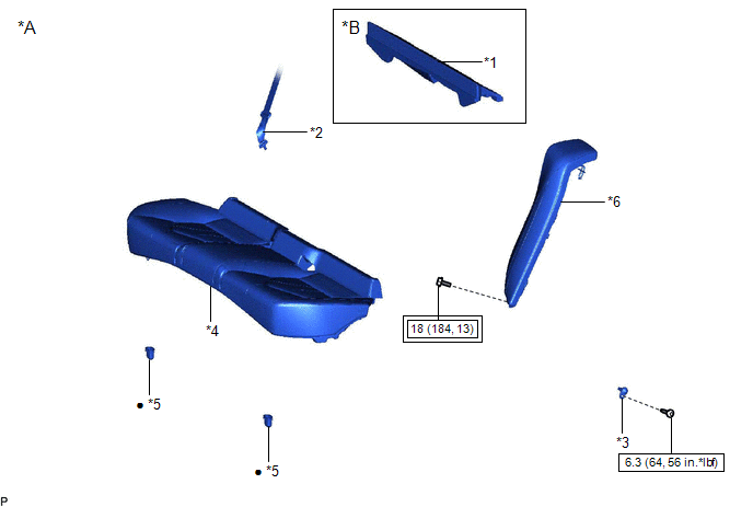
ILLUSTRATION
|
*A | for HV Model |
*B | w/ Seat Heater System |
|
*1 | LUGGAGE COMPARTMENT INNER TRIM PAD |
*2 | REAR CENTER SEAT OUTER BELT ASSEMBLY |
|
*3 | REAR DOOR COURTESY LIGHT SWITCH ASSEMBLY |
*4 | REAR SEAT CUSHION ASSEMBLY |
|
*5 | REAR SEAT CUSHION LOCK HOOK |
*6 | REAR SIDE SEATBACK ASSEMBLY |
|
|
Tightening torque for "Major areas involving basic vehicle performance such as moving/turning/stopping": N*m (kgf*cm, ft.*lbf) |
|
N*m (kgf*cm, ft.*lbf): Specified torque |
|
● | Non-reusable part |
- | - |
INSPECTION
PROCEDURE
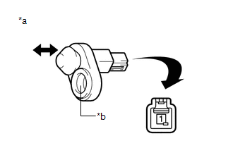
1. INSPECT REAR DOOR COURTESY LIGHT SWITCH ASSEMBLY
|
*a | Component without harness connected (Rear Door Courtesy Light Switch Assembly) |
|
*b | Switch Body |
(a) Measure the resistance according to the value(s) in the table below.
Standard Resistance:
|
Tester Connection | Condition |
Specified Condition |
|---|---|---|
|
1 - Switch body | Not pushed (ON) |
Below 1 Ω |
|
Pushed (OFF) | 10 kΩ or higher |
If the result is not as specified, replace the rear door courtesy light switch assembly.
INSTALLATION
CAUTION / NOTICE / HINT
HINT:
PROCEDURE
1. INSTALL REAR DOOR COURTESY LIGHT SWITCH ASSEMBLY
(a) Connect the connector.
(b) Using a T30 "TORX" socket wrench, install the rear door courtesy light switch assembly with the screw.
Torque:
6.3 N·m {64 kgf·cm, 56 in·lbf}
2. INSTALL REAR SIDE SEATBACK ASSEMBLY
Click here 
3. INSTALL REAR SEAT CUSHION LOCK HOOK
Click here
4. INSTALL REAR SEAT CUSHION ASSEMBLY
Click here
5. CONNECT REAR CENTER SEAT OUTER BELT ASSEMBLY
Click here
6. INSTALL LUGGAGE COMPARTMENT INNER TRIM PAD (w/ Seat Heater System)
Click here
7. INSTALL SPARE WHEEL COVER ASSEMBLY (w/ Seat Heater System)
Click here
8. CONNECT CABLE TO NEGATIVE AUXILIARY BATTERY TERMINAL
for A25A-FXS:
Click here
for 2GR-FKS:
Click here
9. INSTALL LUGGAGE TRIM SERVICE HOLE COVER (for HV Model)
Click here
10. PERFORM DIAGNOSTIC SYSTEM CHECK
for Gasoline Model:
Click here
for HV Model:
Click here
REMOVAL
CAUTION / NOTICE / HINT
The necessary procedures (adjustment, calibration, initialization or registration) that must be performed after parts are removed and installed, or replaced during rear door courtesy light switch assembly removal/installation are shown below.
Necessary Procedure After Parts Removed/Installed/Replaced (for Gasoline Model)|
Replaced Part or Performed Procedure |
Necessary Procedure | Effect/Inoperative Function When Necessary Procedures are not Performed |
Link |
|---|---|---|---|
|
*: When performing learning using the Techstream.
Click here | |||
|
Disconnect cable from negative battery terminal |
Perform steering sensor zero point calibration |
Lane departure alert system (w/ Steering Control) |
|
|
Pre-collision system | |||
|
Intelligent clearance sonar system* | |||
|
Lighting system (for Gasoline Model with Cornering Light) | |||
|
Memorize steering angle neutral point |
Parking assist monitor system |
| |
|
Panoramic view monitor system |
| ||
|
Replaced Part or Performed Procedure |
Necessary Procedure | Effect/Inoperative Function When Necessary Procedures are not Performed |
Link |
|---|---|---|---|
|
*: When performing learning using the Techstream.
Click here | |||
|
Disconnect cable from negative auxiliary battery terminal |
Perform steering sensor zero point calibration |
Lane departure alert system (w/ Steering Control) |
|
|
Pre-collision system | |||
|
Intelligent clearance sonar system* | |||
|
Lighting system (for HV Model with Cornering Light) | |||
|
Memorize steering angle neutral point |
Parking assist monitor system |
| |
|
Panoramic view monitor system |
| ||
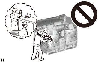
CAUTION:
Some of these service operations affect the SRS airbag system. Read the precautionary notices concerning the SRS airbag system before servicing.
for Gasoline Model:
Click here

for HV Model:
Click here
HINT:
PROCEDURE
1. PRECAUTION
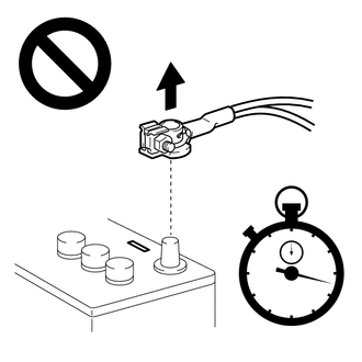
NOTICE:
After turning the engine switch (for Gasoline Model) or power switch (for HV Model) off, waiting time may be required before disconnecting the cable from the negative (-) auxiliary battery terminal. Therefore, make sure to read the disconnecting the cable from the negative (-) auxiliary battery terminal notices before proceeding with work.
Click here
2. REMOVE LUGGAGE TRIM SERVICE HOLE COVER (for HV Model)
Click here
3. DISCONNECT CABLE FROM NEGATIVE AUXILIARY BATTERY TERMINAL
for A25A-FXS:
Click here
for 2GR-FKS:
Click here
CAUTION:
4. REMOVE SPARE WHEEL COVER ASSEMBLY (w/ Seat Heater System)
Click here
5. REMOVE LUGGAGE COMPARTMENT INNER TRIM PAD (w/ Seat Heater System)
Click here
6. DISCONNECT REAR CENTER SEAT OUTER BELT ASSEMBLY
Click here
7. REMOVE REAR SEAT CUSHION ASSEMBLY
Click here
8. REMOVE REAR SEAT CUSHION LOCK HOOK
Click here
9. REMOVE REAR SIDE SEATBACK ASSEMBLY
Click here
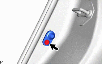
10. REMOVE REAR DOOR COURTESY LIGHT SWITCH ASSEMBLY
| (a) Using a T30 "TORX" socket wrench, remove the screw. |
|
(b) Disconnect the connector to remove the rear door courtesy light switch assembly.
Toyota Avalon (XX50) 2019-2022 Service & Repair Manual > Door / Hatch: Luggage Compartment Door Opener System(for Hv Model)
Customize Parameters CUSTOMIZE PARAMETERS CUSTOMIZE LUGGAGE COMPARTMENT DOOR OPENER SYSTEM HINT: The following items can be customized. NOTICE: When the customer requests a change in a function, first make sure that the function can be customized. Be sure to make a note of the current settings befor ...