COMPONENTS
ILLUSTRATION
|
*1 | CENTER INSTRUMENT CLUSTER FINISH PANEL SUB-ASSEMBLY |
*2 | CENTER NO. 1 INSTRUMENT CLUSTER FINISH PANEL |
|
*3 | CENTER NO. 2 INSTRUMENT CLUSTER FINISH PANEL |
*4 | CONSOLE BOX BEZEL |
|
*5 | CONSOLE BOX POCKET SUB-ASSEMBLY |
*6 | FRONT CONSOLE UPPER PANEL GARNISH |
|
*7 | LOWER INSTRUMENT PANEL FINISH PANEL LH |
*8 | LOWER INSTRUMENT PANEL FINISH PANEL RH |
|
*9 | LOWER INSTRUMENT PANEL SUB-ASSEMBLY |
*10 | RADIO AND DISPLAY RECEIVER ASSEMBLY WITH BRACKET |
|
*11 | REAR UPPER CONSOLE PANEL SUB-ASSEMBLY |
*12 | SHIFT LEVER KNOB SUB-ASSEMBLY |
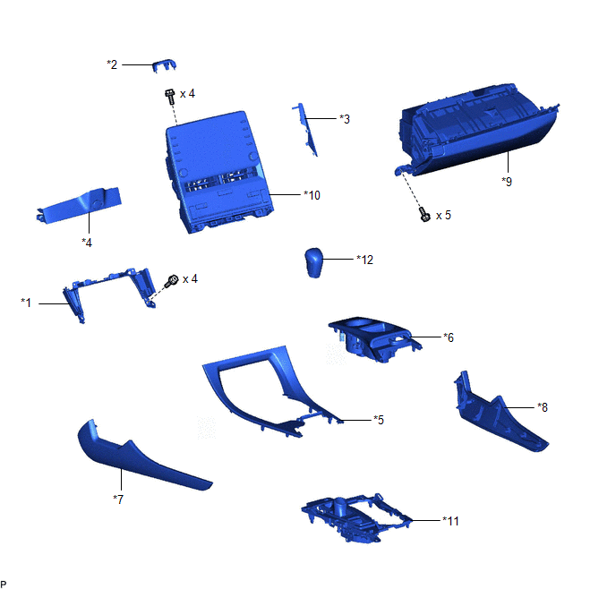
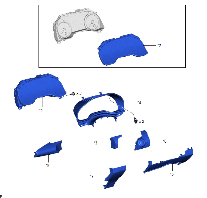
ILLUSTRATION
|
*1 | COMBINATION METER ASSEMBLY |
*2 | COMBINATION METER GLASS |
|
*3 | INSTRUMENT CLUSTER FINISH PANEL GARNISH ASSEMBLY |
*4 | INSTRUMENT CLUSTER FINISH PANEL SUB-ASSEMBLY |
|
*5 | LOWER CENTER INSTRUMENT PANEL FINISH PANEL |
*6 | LOWER INSTRUMENT PANEL FINISH PANEL ASSEMBLY |
|
*7 | LOWER NO. 2 INSTRUMENT PANEL FINISH PANEL |
*8 | NO. 1 INSTRUMENT PANEL GARNISH SUB-ASSEMBLY |
DISASSEMBLY
CAUTION / NOTICE / HINT
NOTICE:
PROCEDURE
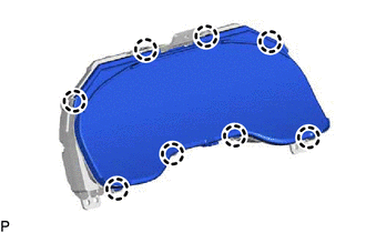
1. REMOVE COMBINATION METER GLASS
| (a) Disengage the 8 claws to remove the combination meter glass. |
|
INSTALLATION
PROCEDURE
1. INSTALL COMBINATION METER ASSEMBLY
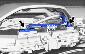
(a) Connect the 2 connectors.
(b) Engage the clamp.
(c) Engage the 2 clips as shown in the illustration.
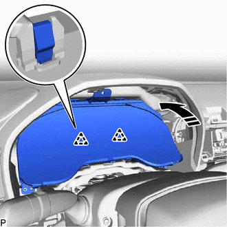
 |
Install in this Direction |
(d) Install the combination meter assembly with the 3 screws.
2. INSTALL INSTRUMENT CLUSTER FINISH PANEL SUB-ASSEMBLY
Click here

3. INSTALL NO. 1 INSTRUMENT PANEL GARNISH SUB-ASSEMBLY
Click here
4. INSTALL LOWER INSTRUMENT PANEL FINISH PANEL ASSEMBLY
Click here
5. INSTALL INSTRUMENT CLUSTER FINISH PANEL GARNISH ASSEMBLY
Click here
6. INSTALL LOWER CENTER INSTRUMENT PANEL FINISH PANEL
Click here
7. INSTALL LOWER NO. 2 INSTRUMENT PANEL FINISH PANEL
Click here
8. INSTALL LOWER INSTRUMENT PANEL SUB-ASSEMBLY
Click here
9. INSTALL RADIO AND DISPLAY RECEIVER ASSEMBLY WITH BRACKET
Click here
10. INSTALL CENTER NO. 2 INSTRUMENT CLUSTER FINISH PANEL
Click here
11. INSTALL CENTER NO. 1 INSTRUMENT CLUSTER FINISH PANEL
Click here
12. INSTALL CONSOLE BOX BEZEL
Click here
13. INSTALL REAR UPPER CONSOLE PANEL SUB-ASSEMBLY
Click here
14. INSTALL SHIFT LEVER KNOB SUB-ASSEMBLY
Click here
15. INSTALL CENTER INSTRUMENT CLUSTER FINISH PANEL SUB-ASSEMBLY
Click here
16. INSTALL CONSOLE BOX POCKET SUB-ASSEMBLY
Click here
17. INSTALL FRONT CONSOLE UPPER PANEL GARNISH
Click here
18. INSTALL LOWER INSTRUMENT PANEL FINISH PANEL RH
Click here
19. INSTALL LOWER INSTRUMENT PANEL FINISH PANEL LH
Click here
20. INSTALL LOWER NO. 2 INSTRUMENT PANEL AIRBAG ASSEMBLY
Click here
21. CUSTOMIZE POWER TILT AND POWER TELESCOPIC STEERING COLUMN SYSTEM (for Power Tilt and Power Telescopic Steering Column)
Click here
REASSEMBLY
CAUTION / NOTICE / HINT
NOTICE:
PROCEDURE
1. INSTALL COMBINATION METER GLASS
| (a) Engage the 8 claws to install the combination meter glass. |
|
REMOVAL
CAUTION / NOTICE / HINT
The necessary procedures (adjustment, calibration, initialization or registration) that must be performed after parts are removed and installed, or replaced during combination meter assembly removal/installation are shown below.
Necessary Procedure After Parts Removed/Installed/Replaced (for Gasoline Model)|
Replaced Part or Performed Procedure |
Necessary Procedure | Effect/Inoperative Function When Necessary Procedures are not Performed |
Link |
|---|---|---|---|
|
*: When performing learning using the Techstream.
Click here | |||
|
Disconnect cable from negative (-) battery terminal |
Perform steering sensor zero point calibration |
Lane Departure Alert System (w/ Steering Control) |
|
|
Pre-collision System | |||
|
Intelligent Clearance Sonar System* | |||
|
Lighting System (for Gasoline Model with Cornering Light) | |||
|
Memorize steering angle neutral point |
Parking Assist Monitor System |
| |
|
Panoramic View Monitor System |
| ||
|
Replaced Part or Performed Procedure |
Necessary Procedure | Effect/Inoperative Function When Necessary Procedures are not Performed |
Link |
|---|---|---|---|
|
*: When performing learning using the Techstream.
Click here | |||
|
Disconnect cable from negative (-) auxiliary battery terminal |
Perform steering sensor zero point calibration |
Lane Departure Alert System (w/ Steering Control) |
|
|
Pre-collision System | |||
|
Intelligent Clearance Sonar System* | |||
|
Lighting System (for HV Model with Cornering Light) | |||
|
Memorize steering angle neutral point |
Parking Assist Monitor System |
| |
|
Panoramic View Monitor System |
| ||
PROCEDURE
1. PRECAUTION
NOTICE:
After turning the engine switch (for Gasoline Model) or power switch (for HV Model) off, waiting time may be required before disconnecting the cable from the negative (-) auxiliary battery terminal. Therefore, make sure to read the disconnecting the cable from the negative (-) auxiliary battery terminal notices before proceeding with work.
Click here

2. CHANGE POWER TILT AND POWER TELESCOPIC STEERING COLUMN SYSTEM SETTINGS (for Power Tilt and Power Telescopic Steering Column)
Click here
3. REMOVE LOWER NO. 2 INSTRUMENT PANEL AIRBAG ASSEMBLY
Click here
4. REMOVE LOWER INSTRUMENT PANEL FINISH PANEL LH
Click here
5. REMOVE LOWER INSTRUMENT PANEL FINISH PANEL RH
Click here
6. REMOVE FRONT CONSOLE UPPER PANEL GARNISH
Click here
7. REMOVE CONSOLE BOX POCKET SUB-ASSEMBLY
Click here
8. REMOVE CENTER INSTRUMENT CLUSTER FINISH PANEL SUB-ASSEMBLY
Click here
9. REMOVE SHIFT LEVER KNOB SUB-ASSEMBLY
Click here
10. REMOVE REAR UPPER CONSOLE PANEL SUB-ASSEMBLY
Click here
11. REMOVE CONSOLE BOX BEZEL
Click here
12. REMOVE CENTER NO. 1 INSTRUMENT CLUSTER FINISH PANEL
Click here
13. REMOVE CENTER NO. 2 INSTRUMENT CLUSTER FINISH PANEL
Click here
14. REMOVE RADIO AND DISPLAY RECEIVER ASSEMBLY WITH BRACKET
Click here
15. REMOVE LOWER INSTRUMENT PANEL SUB-ASSEMBLY
Click here
16. REMOVE LOWER NO. 2 INSTRUMENT PANEL FINISH PANEL
Click here
17. REMOVE LOWER CENTER INSTRUMENT PANEL FINISH PANEL
Click here
18. REMOVE INSTRUMENT CLUSTER FINISH PANEL GARNISH ASSEMBLY
Click here
19. REMOVE LOWER INSTRUMENT PANEL FINISH PANEL ASSEMBLY
Click here
20. REMOVE NO. 1 INSTRUMENT PANEL GARNISH SUB-ASSEMBLY
Click here
21. REMOVE INSTRUMENT CLUSTER FINISH PANEL SUB-ASSEMBLY
Click here
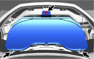
22. REMOVE COMBINATION METER ASSEMBLY
| (a) Remove the 3 screws. |
|
(b) Disengage the 2 clips as shown in the illustration.
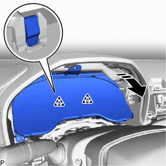
 |
Remove in this Direction |
| (c) Disengage the clamp. |
|
(d) Disconnect the 2 connectors to remove the combination meter assembly.
Toyota Avalon (XX50) 2019-2022 Service & Repair Manual > 2gr-fks Fuel: Fuel Pump(for High Pressure)
Components COMPONENTS ILLUSTRATION *1 FUEL PUMP ASSEMBLY *2 FUEL PUMP PROTECTOR *3 NO. 1 FUEL PIPE SUB-ASSEMBLY *4 NO. 2 FUEL TUBE SUB-ASSEMBLY *5 FUEL PUMP LIFTER ASSEMBLY *6 FUEL PUMP LIFTER GUIDE *7 FUEL PUMP SPACER GASKET *8 FUEL TUBE SUB-ASSEMBLY *9 O-RING - - Tightening torque for "Major areas ...