INSTALLATION PROCEDURE 1. INSTALL COMBINATION METER ASSEMBLY (a) Connect the 2 connectors. (b) Engage the clamp. (c) Engage the 2 clips as shown in the illustration. 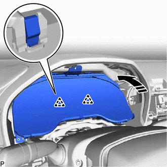
(d) Install the combination meter assembly with the 3 screws. 2. INSTALL INSTRUMENT CLUSTER FINISH PANEL SUB-ASSEMBLY Click here
3. INSTALL NO. 1 INSTRUMENT PANEL GARNISH SUB-ASSEMBLY Click here 4. INSTALL LOWER INSTRUMENT PANEL FINISH PANEL ASSEMBLY Click here 5. INSTALL INSTRUMENT CLUSTER FINISH PANEL GARNISH ASSEMBLY Click here 6. INSTALL LOWER CENTER INSTRUMENT PANEL FINISH PANEL Click here 7. INSTALL LOWER NO. 2 INSTRUMENT PANEL FINISH PANEL Click here 8. INSTALL LOWER INSTRUMENT PANEL SUB-ASSEMBLY Click here 9. INSTALL RADIO AND DISPLAY RECEIVER ASSEMBLY WITH BRACKET Click here 10. INSTALL CENTER NO. 2 INSTRUMENT CLUSTER FINISH PANEL Click here 11. INSTALL CENTER NO. 1 INSTRUMENT CLUSTER FINISH PANEL Click here 12. INSTALL CONSOLE BOX BEZEL Click here 13. INSTALL REAR UPPER CONSOLE PANEL SUB-ASSEMBLY Click here 14. INSTALL SHIFT LEVER KNOB SUB-ASSEMBLY Click here 15. INSTALL CENTER INSTRUMENT CLUSTER FINISH PANEL SUB-ASSEMBLY Click here 16. INSTALL CONSOLE BOX POCKET SUB-ASSEMBLY Click here 17. INSTALL FRONT CONSOLE UPPER PANEL GARNISH Click here 18. INSTALL LOWER INSTRUMENT PANEL FINISH PANEL RH Click here 19. INSTALL LOWER INSTRUMENT PANEL FINISH PANEL LH Click here 20. INSTALL LOWER NO. 2 INSTRUMENT PANEL AIRBAG ASSEMBLY Click here 21. CUSTOMIZE POWER TILT AND POWER TELESCOPIC STEERING COLUMN SYSTEM (for Power Tilt and Power Telescopic Steering Column) Click here |
Toyota Avalon (XX50) 2019-2022 Service & Repair Manual > Electronically Controlled Brake System(for Hv Model): Definition Of Terms
DEFINITION OF TERMS Term Definition Monitor Description Description of what the skid control ECU (brake booster with master cylinder assembly) monitors and how it detects malfunctions (monitoring purpose and details). Related DTCs Group of diagnostic trouble codes that are output by the skid control ...


