DESCRIPTION
The meter mirror sub-assembly receives signals from the radio and display receiver assembly via local bus communication and navigation system information on the headup display.
This DTC is stored when the meter mirror sub-assembly cannot receive the signal.
|
DTC No. | Detection Item |
DTC Detection Condition | Trouble Area |
Memory | Note |
|---|---|---|---|---|---|
|
B132187 | Lost Communication with EMV Missing Message |
Diagnosis Condition:
Malfunction Status:
Malfunction Time:
|
| DTC stored |
- |
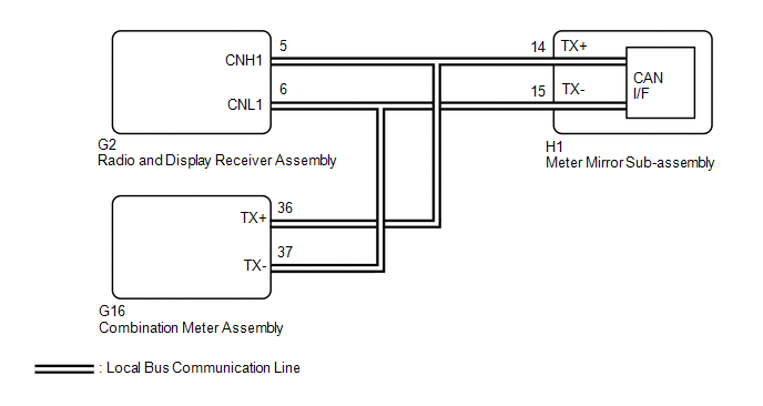
WIRING DIAGRAM
PROCEDURE
| 1. |
CHECK FOR DTC (NAVIGATION SYSTEM) |
(a) Check if navigation system DTCs are output.
Body Electrical > Navigation System > Trouble Codes|
Result | Proceed to |
|---|---|
|
DTCs are not output | A |
|
DTCs are output | B |
| B |
 | GO TO NAVIGATION SYSTEM |
|
| 2. |
CHECK FOR DTC (METER / GAUGE SYSTEM) |
(a) Check if meter / gauge system DTCs are output.
Click here 
|
Result | Proceed to |
|---|---|
|
DTC B132187 is not output |
A |
| DTC B132187 is output |
B |
| A |
| REPLACE METER MIRROR SUB-ASSEMBLY |
| B |
| REPLACE RADIO AND DISPLAY RECEIVER ASSEMBLY |
CUSTOMIZE PARAMETERS
NOTICE:
HINT:
The following items can be customized.
CUSTOMIZE HEADUP DISPLAY SYSTEM
(a) Customizing with the Techstream
(1) Connect the Techstream to the DLC3.
(2) Turn the power switch on (IG).
(3) Turn the Techstream on.
(4) Enter the following menus: Customize Setting / Display.
(5) Select the setting by referring to the table below.
Display|
Tester Display | Description |
Default | Setting |
ECU |
|---|---|---|---|---|
| Projection Adjustment (Tilt) |
Headup display image calibration (tilt calibration) |
Default | $03:Clockwise (+3),$02:Clockwise (+2),$01:Clockwise (+1),$00:Default,$FF:Anti-Clockwise (-1),$FE:Anti-Clockwise (-2),$FD:Anti-Clockwise (-3) | Meter mirror sub-assembly |
|
Projection Adjustment (Keystone) |
Headup display image calibration (keystone calibration) |
Default | $03:Narrow Top (+3),$02:Narrow Top (+2),$01:Narrow Top (+1),$00:Default,$FF:Narrow Bottom (-1),$FE:Narrow Bottom (-2),$FD:Narrow Bottom (-3) |
Meter mirror sub-assembly |
|
Projection Adjustment (Distortion) |
Headup display image calibration (distortion calibration) |
Default | $03:Convex (+3),$02:Convex (+2),$01:Convex (+1),$00:Default,$FF:Concave (-1),$FE:Concave (-2),$FD:Concave (-3) |
Meter mirror sub-assembly |
|
Audio Information Display Function |
Audio system operation status display setting for headup display* |
ON | $00:OFF,$01:ON |
Meter mirror sub-assembly |
|
Master Caution Display Function |
Master warning light display setting for headup display |
ON | $00:OFF,$01:ON |
Meter mirror sub-assembly |
|
Speed Limit Display Function |
Speed limit display setting for headup display |
ON | $00:OFF,$01:ON |
Meter mirror sub-assembly |
|
Turn by Turn Animation Function |
Route guidance to destination display setting for headup display* |
ON | $00:OFF,$01:ON |
Meter mirror sub-assembly |
|
Traffic Sign Recognition Animation Function |
Traffic sign recognition display setting for headup display* |
ON | $00:OFF,$01:ON |
Meter mirror sub-assembly |
|
Memory Call Link Function |
Memory call link setting for headup display image position |
ON | $00:OFF,$01:ON |
Meter mirror sub-assembly |
|
Seat Switch Link Function |
Power seat switch link setting for headup display image position |
ON | $00:OFF,$01:ON |
Meter mirror sub-assembly |
|
ECO Drive Indicator Zone Display Function |
ECO driving indicator zone display setting for headup display* |
ON | $00:OFF,$01:ON |
Meter mirror sub-assembly |
|
Projection Adjustment (Tilt) |
Headup display image calibration (tilt calibration)* |
Default | $05:Clockwise (+5),$04:Clockwise (+4),$03:Clockwise (+3),$02:Clockwise (+2),$01:Clockwise (+1),$00:Default,$FF:Anti-Clockwise (-1),$FE:Anti-Clockwise (-2),$FD:A**cut** |
Meter mirror sub-assembly |
HINT:
(b) Customizing with the multi-information display
(1) Turn the power switch on (IG).
(2) Select the settings tab on the multi-information display and set the customize settings.
|
Display | Detail 1 |
Detail 2 | Description |
Setting | ECU |
|---|---|---|---|---|---|
|
HUD Main | - |
- | Headup display system |
ON/OFF | Meter mirror sub-assembly |
|
HUD Brightness/Position |
Brightness | Display brightness setting for headup display |
- | ||
| Position |
Display position setting for headup display |
- | |||
|
HUD Driving Support | Tachometer Settings |
Tachometer display setting for headup display |
Blank/Hybrid System/Tachometer | ||
|
Navigation | Route guidance to destination display setting for headup display |
ON/OFF | |||
| Driving Assist |
Driving assist display setting for headup display |
ON/OFF | |||
| Compass |
Compass display setting for headup display |
ON/OFF | |||
| Audio |
Audio system-linked display setting for headup display |
ON/OFF | |||
| Rotation |
- | Headup display image calibration (rotation calibration) |
- |
HINT:
Depending on the specifications of the vehicle, some items may not be displayed.
DATA LIST / ACTIVE TEST
DATA LIST
NOTICE:
In the table below, the values listed under "Normal Condition" are reference values. Do not depend solely on these reference values when deciding whether a part is faulty or not.
HINT:
Using the Techstream to read the Data List allows the values or states of switches, sensors, actuators and other items to be read without removing any parts. This non-intrusive inspection can be very useful because intermittent conditions or signals may be discovered before parts or wiring is disturbed. Reading the Data List information early in troubleshooting is one way to save diagnostic time.
(a) Connect the Techstream to the DLC3.
(b) Turn the power switch on (IG).
(c) Turn the Techstream on.
(d) Enter the following menus: Body Electrical / Head Up Display / Data List.
(e) Read the Data List according to the display on the Techstream.
Body Electrical > Head Up Display > Data List|
Tester Display | Measurement Item |
Range | Normal Condition |
Diagnostic Note |
|---|---|---|---|---|
|
Total Distance Traveled |
Total driving distance |
Min.: 0, Max.: 16777215 |
Current total driving distance |
- |
| Total Distance Traveled - Unit |
Total driving distance unit |
km or mile | Current total driving distance unit |
- |
| Main Switch |
Headup display switch (Direct line) |
OFF or ON | OFF: Switch released ON: Switch pushed | Not applicable to this vehicle |
|
+B Voltage | Auxiliary battery voltage |
Min.: 0.0 V, Max.: 25.5 V or Unset |
11 to 14 V | - |
|
Illumination Rate from Illuminance Sensor |
Light control sensor input value |
Min.: 0 lx, Max.: 65535 lx or Unset |
Value according to the brightness is output |
0 is displayed when there is no light |
|
Vehicle Speed Meter | Vehicle speed input value (Brake ECU) |
Min.: 0 km/h (0 mph), Max.: 255 km/h (158 mph) or Unset |
Almost the same as actual vehicle speed |
- |
| Engine RPM |
Engine speed | Min.: 0 rpm, Max.: 12701 rpm or Unset |
Almost the same as actual tachometer |
- |
| Vehicle Speed from Meter ECU |
Vehicle speed input value (Meter ECU) |
Min.: 0 km/h (0 mph), Max.: 255 km/h (158 mph) or Unset |
Almost the same as actual vehicle speed |
- |
| Brightness Up Switch |
Brightness up switch |
OFF or ON | OFF: Switch released ON: Switch pushed | This item can be inspected by adjusting a setting in the HUD settings of the settings tab displayed on the multi-information display. |
|
Brightness Down Switch |
Brightness down switch |
OFF or ON | OFF: Switch released ON: Switch pushed | This item can be inspected by adjusting a setting in the HUD settings of the settings tab displayed on the multi-information display. |
|
Projection Position Up Switch |
Projection position up switch |
OFF or ON | OFF: Switch released ON: Switch pushed | This item can be inspected by adjusting a setting in the HUD settings of the settings tab displayed on the multi-information display. |
|
Projection Position Down Switch |
Projection position down switch |
OFF or ON | OFF: Switch released ON: Switch pushed | This item can be inspected by adjusting a setting in the HUD settings of the settings tab displayed on the multi-information display. |
|
Display Change Switch | Headup display switch (CAN communication line) |
OFF or ON | OFF: Switch released ON: Switch pushed | - |
|
Display Angle | Headup display angle |
Min.: -12.7 deg, Max.: 12.8 deg or Unset |
Actual headup display angle |
|
| Ambient Temperature (Celsius) |
Outside temperature (Celsius) |
Min.: -40.0°C, Max.: 87.1°C or Unset |
Almost the same as actual outside temperature |
Not applicable to this vehicle |
|
Ambient Temperature (Fahrenheit) |
Outside temperature (Fahrenheit) |
Min.: -40°F, Max.: 215°F or Unset |
Almost the same as actual outside temperature |
- |
| Illumination Rate from Light Control Sensor |
Light control sensor input value |
Min.: 0 lx, Max.: 65535 lx or Unset |
Value according to the brightness is output |
- |
| LDA System |
Existence of lane departure alert system |
Without or With | Without: w/o Lane Departure Alert System With: w/ Lane Departure Alert System |
- |
| PCS System |
Existence of pre-collision system |
Without or With | Without: w/o Pre-collision System With: w/ Pre-collision System |
- |
| ICS System |
Existence of intelligent clearance sonar system |
Without or With | Without: w/o Intelligent Clearance Sonar System With: w/ Intelligent Clearance Sonar System |
- |
| Radar Cruise System |
Existence of dynamic radar cruise control system |
Without or With | Without: w/o Dynamic Radar Cruise Control System With: w/ Dynamic Radar Cruise Control System |
- |
| Clearance Sonar System |
Existence of intuitive parking assist system |
Without or With | Without: w/o Intuitive Parking Assist System With: w/ Intuitive Parking Assist System |
- |
| Road Sign Assist System |
Existence of road sign assist system |
Without or With | Without: w/o Road Sign Assist System With: w/ Road Sign Assist System |
- |
| ITS System |
Existence of ITS | Without or With |
Without: w/o ITS Connect With: w/ ITS Connect |
- |
| HV System Indicator |
Hybrid system indicator value |
Min.: -101%, Max.: 511% or Unset |
Current hybrid system indicator value |
"Unset" is displayed when the vehicle is stopped and the power switch is on (READY). |
|
Navigation System | Existence of navigation system |
Without or With | Without: w/o Navigation System With: w/ Navigation System |
- |
| Audio Information Display Function |
Setting of audio system operation status display |
OFF or ON | OFF: Audio system operation status display not displayed ON: Audio system operation status display displayed |
Not applicable to this vehicle |
|
Master Caution Display Function |
Setting of master warning light |
OFF or ON | OFF: Master warning light not displayed ON: Master warning light displayed |
Displays customize setting of Master Warning Light Function |
|
Speed Limit Display Function |
Setting of speed limit display |
OFF or ON | OFF: Speed limit display not displayed ON: Speed limit display displayed |
Displays customize setting of Speed Limit Display Function |
|
Turn by Turn Animation Function |
Setting of route guidance to destination display |
OFF or ON | OFF: Route guidance to destination display not displayed ON: Route guidance to destination display displayed |
Not applicable to this vehicle |
|
Traffic Sign Recognition Animation Function |
Setting of traffic sign recognition display |
OFF or ON | OFF: Traffic sign recognition display not displayed ON: Traffic sign recognition display displayed |
Not applicable to this vehicle |
|
Memory Call Link Function |
Setting of headup display memory call link function |
OFF or ON | OFF: Memory call link function off ON: Memory call link function on |
Displays customize setting of Memory Call Link Function |
|
Seat Switch Link Function |
Setting of headup display power seat switch link function |
OFF or ON | OFF: Power seat switch link function off ON: Power seat switch link function on |
Displays customize setting of Power Seat Switch Link Function |
|
ECO Drive Indicator Zone Display Function |
Setting of ECO driving indicator zone |
OFF or ON | OFF: Eco driving indicator zone not displayed ON: Eco driving indicator zone displayed |
Not applicable to this vehicle |
|
Color Test Screen (Black) |
Active Test color test screen condition |
OFF or ON | Current Active Test color test screen condition displayed |
- |
| Color Test Screen (White) |
Active Test color test screen condition |
OFF or ON | Current Active Test color test screen condition displayed |
- |
| Color Test Screen (Red) |
Active Test color test screen condition |
OFF or ON | Current Active Test color test screen condition displayed |
- |
| Color Test Screen (Green) |
Active Test color test screen condition |
OFF or ON | Current Active Test color test screen condition displayed |
- |
| Color Test Screen (Blue) |
Active Test color test screen condition |
OFF or ON | Current Active Test color test screen condition displayed |
- |
| Color Test Screen (Color Bars) |
Active Test color test screen condition |
OFF or ON | Current Active Test color test screen condition displayed |
- |
| Color Test Screen (Adjustment) |
Active Test color test screen condition |
OFF or ON | Current Active Test color test screen condition displayed |
- |
| Display Brightness |
Active Test display brightness screen |
Min.: 0%, Max.: 100% | Current Active Test display brightness screen condition displayed |
- |
| Display Position |
Active Test display position screen |
Up (+3), Up (+2), Up (+1), Center, Down (-1), Down (-2) or Down (-3) |
Current Active Test display position screen condition displayed |
- |
| Pedestrian Alert System |
Existence of pedestrian reminder system |
Without or With | Without: w/o Pedestrian Reminder System With: w/ Pedestrian Reminder System |
- |
| FCTA System |
Existence of front cross traffic alert system |
Without or With | Without: w/o Front Cross Traffic Alert System With: w/ Front Cross Traffic Alert System |
- |
| LTC System |
Existence of lane tracing control system |
Without or With | Without: w/o Lane Tracing Control System With: w/ Lane Tracing Control System |
- |
| LCS System |
Existence of lane change assist system |
Without or With | Without: w/o Lane Change Assist System With: w/ Lane Change Assist System |
- |
| LVN System |
Existence of traffic movement notification system |
Without or With | Without: w/o Traffic Movement Notification System With: w/ Traffic Movement Notification System |
- |
| Driver Emergency Stop Assist System |
Existence of driver emergency stop assist system |
Without or With | Without: w/o Driver Emergency Stop Assist System With: w/ Driver Emergency Stop Assist System |
- |
HINT:
Depending on the specifications of the vehicle, some items may not be displayed.
HINT:
Using the Techstream to perform Active Tests allows relays, VSVs, actuators and other items to be operated without removing any parts. This non-intrusive functional inspection can be very useful because intermittent operation may be discovered before parts or wiring is disturbed. Performing Active Tests early in troubleshooting is one way to save diagnostic time. Data List information can be displayed while performing Active Tests.
ACTIVE TEST
(a) Connect the Techstream to the DLC3.
(b) Turn the power switch on (IG).
(c) Turn the Techstream on.
(d) Enter the following menus: Body Electrical / Head Up Display / Active Test.
(e) Perform the Active Test according the display on the Techstream.
Body Electrical > Head Up Display > Active Test|
Tester Display | Measurement Item |
Control Range | Diagnostic Note |
|---|---|---|---|
|
Color Test Screen (Black) |
Headup display (Black color) |
ON | - |
|
Color Test Screen (White) |
Headup display (White color) |
ON | - |
|
Color Test Screen (Red) |
Headup display (Red color) |
ON | - |
|
Color Test Screen (Green) |
Headup display (Green color) |
ON | - |
|
Color Test Screen (Blue) |
Headup display (Blue color) |
ON | - |
|
Color Test Screen (Color Bars) |
Headup display (Color bars) |
ON | - |
|
Color Test Screen (Adjustment) |
Headup display (Adjustment screen) |
ON | - |
|
Display Brightness | Headup display (Display brightness) |
0 to 100% | - |
|
Display Position | Headup display (Display position) |
Up (+3), Up (+2), Up (+1), Center, Down (-1), Down (-2) or Down (-3) |
- |
HINT:
Depending on the specifications of the vehicle, some items may not be displayed.
DIAGNOSIS SYSTEM
CHECK DLC3
(a) Check the DLC3.
Click here 
DIAGNOSTIC TROUBLE CODE CHART
Headup Display System|
DTC No. | Detection Item |
Memory | Note |
Link |
|---|---|---|---|---|
| B132187 |
Lost Communication with EMV Missing Message |
DTC stored | - |
|
|
U010087 | Lost Communication With ECM/PCM "A" Missing Message |
DTC stored | - |
|
|
U012987 | Lost Communication With Brake System Control Module Missing Message |
DTC stored | - |
|
|
U014287 | Lost Communication with Body Control Module "B" Missing Message |
DTC stored | - |
|
|
U015587 | Lost Communication with Instrument Panel Cluster (IPC) Control Module Missing Message |
DTC stored | - |
|
|
U016387 | Lost Communication with Navigation Control Module Missing Message |
DTC stored | - |
|
|
U016487 | Lost Communication with HVAC Control Module Missing Message |
DTC stored | - |
|
|
U023A87 | Lost Communication with Image Processing Module "A" Missing Message |
DTC stored | - |
|
|
U029387 | Lost Communication With Hybrid Powertrain Control Module Missing Message |
DTC stored | - |
|
|
U110487 | Lost Communication with Driving Support ECU Missing Message |
DTC stored | - |
|
|
U111087 | Lost Communication with Intuitive Parking Assist Module Missing Message |
DTC stored | w/ Intelligent Clearance Sonar System |
|
DTC CHECK / CLEAR
CHECK FOR DTC (HEADUP DISPLAY SYSTEM)
(a) Connect the Techstream to the DLC3.
(b) Turn the power switch on (IG).
(c) Turn the Techstream on.
(d) Enter the following menus: Body Electrical / Head Up Display / Trouble Codes.
Body Electrical > Head Up Display > Trouble Codes(e) Check for DTCs.
CLEAR DTC
(a) Connect the Techstream to the DLC3.
(b) Turn the power switch on (IG).
(c) Turn the Techstream on.
(d) Enter the following menus: Body Electrical / Head Up Display / Clear DTCs.
Body Electrical > Head Up Display > Clear DTCs(e) Clear the DTCs.
CAUTION / NOTICE / HINT
HINT:
PROCEDURE
|
1. | VEHICLE BROUGHT TO WORKSHOP |
|
| 2. |
CUSTOMER PROBLEM ANALYSIS |
HINT:
|
What |
Vehicle model, system name |
|
When |
Date, time, occurrence frequency |
|
Where |
Road conditions |
|
Under what conditions? |
Driving conditions, weather conditions |
|
How did it happen? |
Problem symptoms |
|
| 3. |
INSPECT AUXILIARY BATTERY VOLTAGE |
(a) Measure the auxiliary battery voltage with the power switch off.
Standard Voltage:
11 to 14 V
If the voltage is below 11 V, recharge or replace the auxiliary battery before proceeding to the next step.
(b) Check the fuses and relays.
(c) Check the connector connections and terminals to make sure that there are no abnormalities such as loose connections, deformation, etc.
|
| 4. |
CHECK CAN COMMUNICATION SYSTEM* |
(a) Using the Techstream, check for CAN communication system DTCs.
Click here 
|
Result | Proceed to |
|---|---|
|
CAN DTCs are not output |
A |
| CAN DTCs are output |
B |
| B |
 | GO TO CAN COMMUNICATION SYSTEM |
|
| 5. |
CHECK FOR DTC* (HEADUP DISPLAY SYSTEM) |
(a) Check for DTCs.
Body Electrical > Head Up Display > Trouble Codes|
Result | Proceed to |
|---|---|
|
DTCs are not output | A |
|
DTCs are output | B |
| B |
| GO TO DIAGNOSTIC TROUBLE CODE CHART |
|
| 6. |
PROBLEM SYMPTOM CONFIRMATION |
|
| 7. |
SYMPTOM SIMULATION |
|
| 8. |
PROBLEM SYMPTOMS TABLE |
(a) Refer to Problem Symptoms Table.
Click here
|
Result | Proceed to |
|---|---|
|
Fault is not listed in Problem Symptoms Table |
A |
| Fault is listed in Problem Symptoms Table |
B |
| B |
| GO TO PROBLEM SYMPTOMS TABLE |
|
| 9. |
OVERALL ANALYSIS AND TROUBLESHOOTING* |
(a) Terminals of ECU.
Click here
(b) Data List / Active Test.
Click here
|
| 10. |
CIRCUIT INSPECTION |
|
| 11. |
ADJUST, REPAIR OR REPLACE |
|
| 12. |
CONFIRMATION TEST |
| NEXT | | END |
PARTS LOCATION
ILLUSTRATION
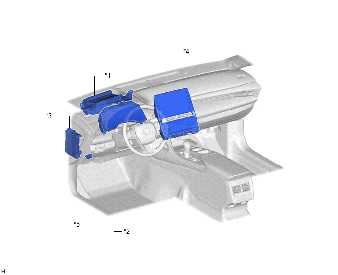
|
*1 | METER MIRROR SUB-ASSEMBLY |
*2 | COMBINATION METER ASSEMBLY |
|
*3 | INSTRUMENT PANEL JUNCTION BLOCK ASSEMBLY - ECU-DCC NO. 2 FUSE - ECU-IG1 NO. 4 FUSE |
*4 | RADIO AND DISPLAY RECEIVER ASSEMBLY |
|
*5 | DLC3 |
- | - |
PRECAUTION
PRECAUTION FOR DISCONNECTING CABLE FROM NEGATIVE AUXILIARY BATTERY TERMINAL
NOTICE:
When disconnecting the cable from the negative (-) auxiliary battery terminal, initialize the following systems after the cable is reconnected.
|
System Name | See Procedure |
|---|---|
|
Lane Departure Alert System (w/ Steering Control) |
|
|
Intelligent Clearance Sonar System | |
| Parking Assist Monitor System | |
|
Panoramic View Monitor System | |
|
Pre-collision System | |
| Lighting System (for HV Model with Cornering Light) |
PROBLEM SYMPTOMS TABLE
NOTICE:
When replacing the combination meter assembly, always replace it with a new one. If a combination meter assembly which was installed to another vehicle is used, the information stored in it will not match the information from the vehicle and a DTC may be stored.
HINT:
|
Symptom | Suspected Area |
Link |
|---|---|---|
|
Headup display is not displayed |
Wire harness or connector |
- |
| Read the Data List (Display Change Switch) |
| |
|
Meter mirror sub-assembly |
| |
|
Combination meter assembly |
| |
|
Brightness of the headup display does not change |
Check customize parameters (HUD Brightness/Position) |
|
|
Perform Active Test (Display Brightness) |
| |
|
Read the Data List (Brightness Up Switch, Brightness Down Switch) |
| |
|
Meter mirror sub-assembly |
| |
|
Combination meter assembly |
| |
|
Headup display is not displayed in the correct position |
Headup display position initialization |
|
|
Check customize parameters (HUD Brightness/Position) |
| |
|
Perform Active Test (Display Position) |
| |
|
Read the Data List (Projection Position Up Switch, Projection Position Down Switch) |
| |
|
Meter mirror sub-assembly |
| |
|
Combination meter assembly |
| |
|
Other headup display malfunction (Other systems are normal) |
Meter mirror sub-assembly |
|
SYSTEM DESCRIPTION
HEADUP DISPLAY SYSTEM DESCRIPTION
(a) The headup display system receives signals from each ECU via CAN communication and local bus communication and displays driving assist information, such as current vehicle speed, on the windshield glass assembly. The brightness and position of the headup display can be changed on the settings screen of the multi-information display. Depending on certain conditions, the following items can be displayed on the headup display:
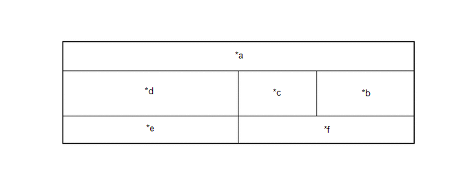
|
*a | Display Area A |
*b | Display Area B |
|
*c | Display Area C |
*d | Display Area D |
|
*e | Display Area E |
*f | Display Area F |
|
Display Area | Display |
|---|---|
|
A, B, C, D, E, F | Pre-collision system warning message |
|
Intelligent clearance sonar system warning message* | |
|
Opening | |
| A, C, D, E, F |
Intelligent clearance sonar system caution message* |
|
A, D, E, F | Display position adjustment frame |
|
D, E | Dynamic radar cruise control system warning |
|
Lane departure alert system warning | |
|
Clearance sonar detection* | |
|
Route guidance to destination (Navigation system) | |
|
B | Speedometer |
|
Speedometer unit | |
|
C | Shift position |
|
Speed limit (Navigation system) | |
|
D | Dynamic radar cruise control system information |
|
Lane departure alert system information | |
|
Compass (Navigation system) | |
|
Street name (Navigation system) | |
|
E | Unsteady driving alert |
|
Hands off steering wheel alert | |
|
Master warning light | |
|
Icy warning light | |
|
Information | |
|
Dynamic radar cruise control system notification message | |
|
Audio system operation status | |
|
Hands-free system status | |
|
F | Outside temperature |
|
Hybrid system indicator | |
|
Tachometer |
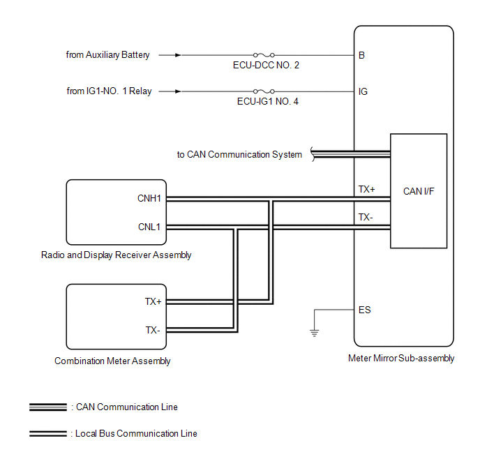
SYSTEM DIAGRAM
HINT:
Refer to System Diagram of CAN Communication System.
Click here 
TERMINALS OF ECU
METER MIRROR SUB-ASSEMBLY

(a) Measure the voltage and resistance according to the value(s) in the table below.
|
Terminal No. (Symbol) | Wiring Color |
Terminal Description | Signal Input/Output |
Condition | Specified Condition |
|---|---|---|---|---|---|
|
H1-1 (IG) - Body ground |
L - Body ground | Power switch signal |
- | Power switch off → Power switch on (IG) |
Below 1 V → 11 to 14 V |
|
H1-2 (B) - Body ground |
P - Body ground | Auxiliary battery |
- | Power switch off |
11 to 14 V |
|
H1-4 (ES) - Body ground |
W-B - Body ground | Ground |
- | Always |
Below 1 Ω |
|
H1-12 (MPX1) | P |
CAN communication line |
Input/Output | - |
- |
| H1-13 (MPX2) |
R | CAN communication line |
Input/Output | - |
- |
| H1-14 (TX+) |
L | Local bus communication line |
Input/Output | - |
- |
| H1-15 (TX-) |
GR | Local bus communication line |
Input/Output | - |
- |
DESCRIPTION
The meter mirror sub-assembly communicates with each ECU via CAN communication.
|
DTC No. | Detection Item |
DTC Detection Condition | Trouble Area |
Memory | Note |
|---|---|---|---|---|---|
|
U010087 | Lost Communication With ECM/PCM "A" Missing Message |
Diagnosis Condition:
Malfunction Status:
Malfunction Time:
|
| DTC stored |
- |
| U012987 |
Lost Communication With Brake System Control Module Missing Message |
Diagnosis Condition:
Malfunction Status:
Malfunction Time:
|
| DTC stored |
- |
| U014287 |
Lost Communication with Body Control Module "B" Missing Message |
Diagnosis Condition:
Malfunction Status:
Malfunction Time:
|
| DTC stored |
- |
| U015587 |
Lost Communication with Instrument Panel Cluster (IPC) Control Module Missing Message |
Diagnosis Condition:
Malfunction Status:
Malfunction Time:
|
| DTC stored |
- |
| U016387 |
Lost Communication with Navigation Control Module Missing Message |
Diagnosis Condition:
Malfunction Status:
Malfunction Time:
|
| DTC stored |
- |
| U016487 |
Lost Communication with HVAC Control Module Missing Message |
Diagnosis Condition:
Malfunction Status:
Malfunction Time:
|
| DTC stored |
- |
| U023A87 |
Lost Communication with Image Processing Module "A" Missing Message |
Diagnosis Condition:
Malfunction Status:
Malfunction Time:
|
| DTC stored |
- |
| U029387 |
Lost Communication With Hybrid Powertrain Control Module Missing Message |
Diagnosis Condition:
Malfunction Status:
Malfunction Time:
|
| DTC stored |
- |
| U110487 |
Lost Communication with Driving Support ECU Missing Message |
Diagnosis Condition:
Malfunction Status:
Malfunction Time:
|
| DTC stored |
- |
| U111087 |
Lost Communication with Intuitive Parking Assist Module Missing Message |
Diagnosis Condition:
Malfunction Status:
Malfunction Time:
|
| DTC stored |
w/ Intelligent Clearance Sonar System |
PROCEDURE
| 1. |
CHECK FOR DTC (HEADUP DISPLAY SYSTEM) |
(a) Check for DTCs are output.
Body Electrical > Head Up Display > Trouble Codes| NEXT |  | GO TO CAN COMMUNICATION SYSTEM |
UTILITY
MIRROR POSITION INITIALIZATION
HINT:
Use this procedure to return the display of the headup display to its initial position.
(a) Connect the Techstream to the DLC3.
(b) Turn the power switch on (IG).
(c) Turn the Techstream on.
(d) Enter the following menus: Body Electrical / Head Up Display / Utility / Mirror Position Reset.
(e) Perform the procedure displayed on the Techstream.
Body Electrical > Head Up Display > Utility|
Tester Display |
|---|
| Mirror Position Reset |
Toyota Avalon (XX50) 2019-2022 Service & Repair Manual > Lighting (ext): Lighting System(for Gasoline Model With Cornering Light)
Automatic High Beam Switch Indicator does not Come ON DESCRIPTION When the automatic high beam system is on, the main body ECU (multiplex network body ECU) illuminates the auto high beam switch indicator. WIRING DIAGRAM CAUTION / NOTICE / HINT NOTICE: Inspect the fuses for circuits related to this s ...


