COMPONENTS
ILLUSTRATION
|
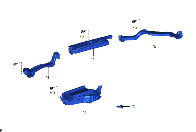
*1 | DEFROSTER NOZZLE ASSEMBLY |
*2 | METER MIRROR SUB-ASSEMBLY |
|
*3 | METER MIRROR WIRE |
*4 | NO. 1 SIDE DEFROSTER NOZZLE DUCT |
|
*5 | NO. 2 SIDE DEFROSTER NOZZLE DUCT |
- | - |
INSTALLATION
PROCEDURE
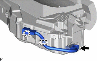
1. INSTALL METER MIRROR WIRE
(a) Engage the clamp and claw.
(b) Connect the connector to install the meter mirror wire.
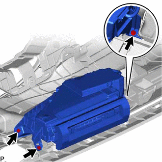
2. INSTALL METER MIRROR SUB-ASSEMBLY
(a) Install the meter mirror sub-assembly with the 3 screws.
3. INSTALL DEFROSTER NOZZLE ASSEMBLY
Click here

4. INSTALL NO. 2 SIDE DEFROSTER NOZZLE DUCT
Click here
5. INSTALL NO. 1 SIDE DEFROSTER NOZZLE DUCT
Click here
6. INSTALL INSTRUMENT PANEL SAFETY PAD SUB-ASSEMBLY
Click here
REMOVAL
CAUTION / NOTICE / HINT
The necessary procedures (adjustment, calibration, initialization or registration) that must be performed after parts are removed and installed, or replaced during headup display (meter mirror sub-assembly) removal/installation are shown below.
Necessary Procedure After Parts Removed/Installed/Replaced (for Gasoline Model)|
Replaced Part or Performed Procedure |
Necessary Procedure | Effect/Inoperative Function When Necessary Procedures are not Performed |
Link |
|---|---|---|---|
|
*: When performing learning using the Techstream.
Click here | |||
|
Disconnect cable from negative (-) battery terminal |
Perform steering sensor zero point calibration |
Lane Departure Alert System (w/ Steering Control) |
|
|
Pre-collision System | |||
|
Intelligent Clearance Sonar System* | |||
|
Lighting System (for Gasoline Model with Cornering Light) | |||
|
Memorize steering angle neutral point |
Parking Assist Monitor System |
| |
|
Panoramic View Monitor System |
| ||
|
Replaced Part or Performed Procedure |
Necessary Procedure | Effect/Inoperative Function When Necessary Procedures are not Performed |
Link |
|---|---|---|---|
|
*: When performing learning using the Techstream.
Click here | |||
|
Disconnect cable from negative (-) auxiliary battery terminal |
Perform steering sensor zero point calibration |
Lane Departure Alert System (w/ Steering Control) |
|
|
Pre-collision System | |||
|
Intelligent Clearance Sonar System* | |||
|
Lighting System (for HV Model with Cornering Light) | |||
|
Memorize steering angle neutral point |
Parking Assist Monitor System |
| |
|
Panoramic View Monitor System |
| ||
CAUTION:
Be sure to read Precaution thoroughly before servicing.
for Gasoline Model: Click here

for HV Model: Click here
PROCEDURE
1. REMOVE INSTRUMENT PANEL SAFETY PAD SUB-ASSEMBLY
Click here
2. REMOVE NO. 1 SIDE DEFROSTER NOZZLE DUCT
Click here
3. REMOVE NO. 2 SIDE DEFROSTER NOZZLE DUCT
Click here
4. REMOVE DEFROSTER NOZZLE ASSEMBLY
Click here
5. REMOVE METER MIRROR SUB-ASSEMBLY
| (a) Remove the 3 screws and meter mirror sub-assembly. |
|
6. REMOVE METER MIRROR WIRE
| (a) Disconnect the connector. |
|
(b) Disengage the claw and clamp to remove the meter mirror wire.
Toyota Avalon (XX50) 2019-2022 Service & Repair Manual > Heating / Air Conditioning: Ambient Temperature Sensor(for A25a-fxs)
Components COMPONENTS ILLUSTRATION *1 FRONT RADIATOR SIDE AIR GUIDE PLATE LH *2 THERMISTOR ASSEMBLY Inspection INSPECTION PROCEDURE 1. INSPECT THERMISTOR ASSEMBLY (a) Measure the resistance according to the value(s) in the table below. Standard Resistance: Tester Connection Condition Specified Condi ...