DESCRIPTION This DTC is stored when the combination meter assembly detects a short in a turn signal light circuit. HINT: If there is a short in a turn signal light circuit, all of the turn signal lights in that circuit will not blink.
WIRING DIAGRAM LH SIDE 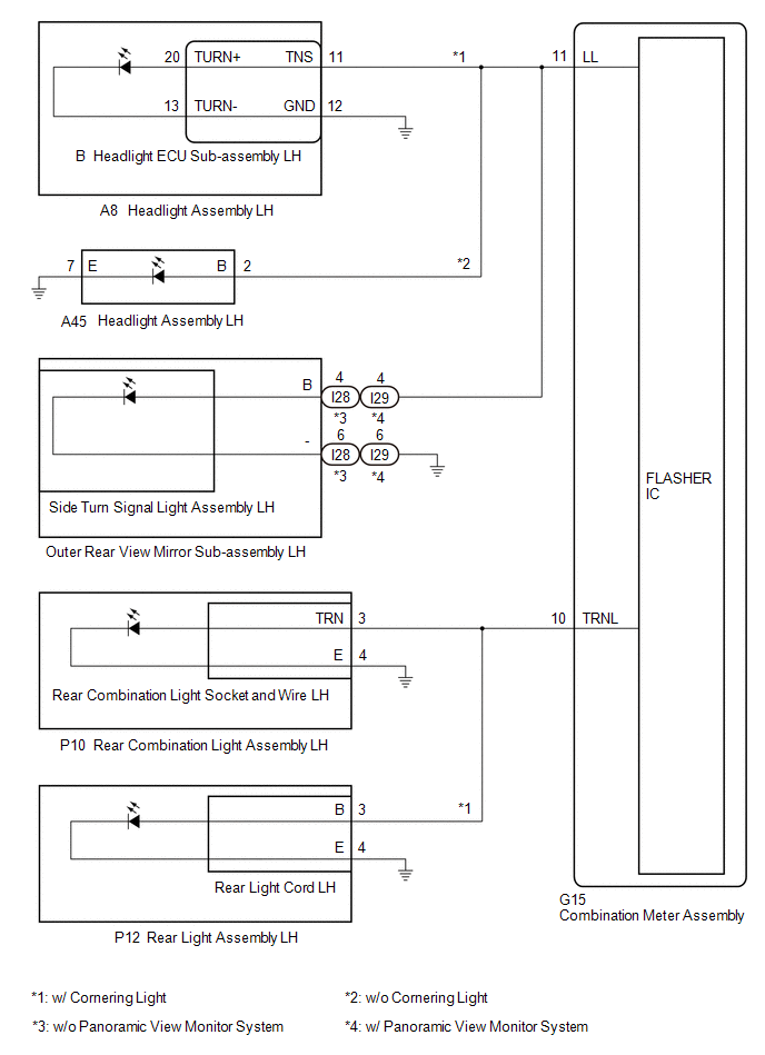 RH SIDE 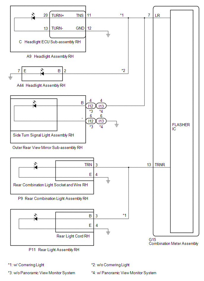 CAUTION / NOTICE / HINT NOTICE: When replacing the combination meter assembly, always replace it with a new one. If a combination meter assembly which was installed to another vehicle is used, the information stored in it will not match the information from the vehicle and a DTC may be stored. PROCEDURE
(a) Inspect the illumination of each turn signal light.
(a) Choose the model to be inspected.
(a) Disconnect the P12 rear light assembly LH connector. (b) Operate the headlight dimmer switch assembly and check that the LH side turn signal lights other than the rear turn signal light blink. HINT: If the LH side turn signal lights blink, the rear light assembly LH is malfunctioning.
(a) Interchange the rear light cord LH with RH and connect the connectors. Click here (b) Check that the rear turn signal light operates normally. OK: Rear turn signal light blinks.
(a) Connect the P12 rear light assembly LH connector. (b) Disconnect the P10 rear combination light assembly LH connector. (c) Operate the headlight dimmer switch assembly and check that the LH side turn signal lights other than the rear turn signal light blink. HINT: If the LH side turn signal lights blink, the rear combination light assembly LH is malfunctioning.
(a) Interchange the rear combination light socket and wire LH with RH and connect the connectors. Click here (b) Check that the rear turn signal light operates normally. OK: Rear turn signal light blinks.
(a) Disconnect the P12 rear light assembly LH connector. (b) Disconnect the G15 combination meter assembly connector. (c) Measure the resistance according to the value(s) in the table below. Standard Resistance:
(a) Connect the P10 rear combination light assembly LH connector. (b) Connect the P12 rear light assembly LH connector. (c) Connect the G15 combination meter assembly connector. (d) Disconnect the I28 outer rear view mirror sub-assembly LH*1 connector. (e) Disconnect the I29 outer rear view mirror sub-assembly LH*2 connector. (f) Operate the headlight dimmer switch assembly and check that the LH side turn signal lights other than the side turn signal light blink. HINT: If the LH side turn signal lights blink, the outer rear view mirror sub-assembly LH is malfunctioning.
(a) Remove the side turn signal light assembly LH. Click here
(b) Inspect the side turn signal light assembly LH. Click here
(a) Connect the I28 outer rear view mirror sub-assembly LH*1 connector. (b) Connect the I29 outer rear view mirror sub-assembly LH*2 connector. (c) Disconnect the A8 headlight assembly LH connector. (d) Operate the headlight dimmer switch assembly and check that the LH side turn signal lights other than the headlight turn signal light blink. HINT: If the LH side turn signal lights blink, the headlight assembly LH is malfunctioning.
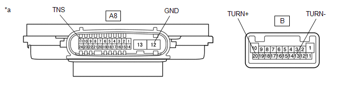
(a) Remove the headlight ECU sub-assembly LH. Click here
(b) Measure the resistance according to the value(s) in the table below. Standard Resistance:
(a) Disconnect the G15 combination meter assembly connector. (b) Disconnect the I28 outer rear view mirror sub-assembly LH*1 connector. (c) Disconnect the I29 outer rear view mirror sub-assembly LH*2 connector. (d) Measure the resistance according to the value(s) in the table below. Standard Resistance:
(a) Disconnect the P10 rear combination light assembly LH connector. (b) Operate the headlight dimmer switch assembly and check that the LH side turn signal lights other than the rear turn signal light blink. HINT: If the LH side turn signal lights blink, the rear combination light assembly LH is malfunctioning.
(a) Interchange the rear combination light socket and wire LH with RH and connect the connectors. Click here (b) Check that the rear turn signal light operates normally. OK: Rear turn signal light blinks.
(a) Disconnect the G15 combination meter assembly connector. (b) Measure the resistance according to the value(s) in the table below. Standard Resistance:
(a) Connect the P10 rear combination light assembly LH connector. (b) Connect the G15 combination meter assembly connector. (c) Disconnect the I29 outer rear view mirror sub-assembly LH connector. (d) Operate the headlight dimmer switch assembly and check that the LH side turn signal lights other than the side turn signal light blink. HINT: If the LH side turn signal lights blink, the outer rear view mirror sub-assembly LH is malfunctioning.
(a) Remove the side turn signal light assembly LH. Click here
(b) Inspect the side turn signal light assembly LH. Click here
(a) Connect the I29 outer rear view mirror sub-assembly LH connector. (b) Disconnect the A45 headlight assembly LH connector. (c) Operate the headlight dimmer switch assembly and check that the LH side turn signal lights other than the headlight turn signal light blink. HINT: If the LH side turn signal lights blink, the headlight assembly LH is malfunctioning.
(a) Disconnect the G15 combination meter assembly connector. (b) Disconnect the I29 outer rear view mirror sub-assembly LH connector. (c) Measure the resistance according to the value(s) in the table below. Standard Resistance:
(a) Choose the model to be inspected.
(a) Disconnect the P11 rear light assembly RH connector. (b) Operate the headlight dimmer switch assembly and check that the RH side turn signal lights other than the rear turn signal light blink. HINT: If the RH side turn signal lights blink, the rear light assembly RH is malfunctioning.
(a) Interchange the rear light cord RH with LH and connect the connectors. Click here (b) Check that the rear turn signal light operates normally. OK: Rear turn signal light blinks.
(a) Connect the P11 rear light assembly RH connector. (b) Disconnect the P9 rear combination light assembly RH connector. (c) Operate the headlight dimmer switch assembly and check that the RH side turn signal lights other than the rear turn signal light blink. HINT: If the RH side turn signal lights blink, the rear combination light assembly RH is malfunctioning.
(a) Interchange the rear combination light socket and wire RH with LH and connect the connectors. Click here (b) Check that the rear turn signal light operates normally. OK: Rear turn signal light blinks.
(a) Disconnect the P11 rear light assembly RH connector. (b) Disconnect the G15 combination meter assembly connector. (c) Measure the resistance according to the value(s) in the table below. Standard Resistance:
(a) Connect the P9 rear combination light assembly RH connector. (b) Connect the P11 rear light assembly RH connector. (c) Connect the G15 combination meter assembly connector. (d) Disconnect the I12 outer rear view mirror sub-assembly RH*1 connector. (e) Disconnect the I13 outer rear view mirror sub-assembly RH*2 connector. (f) Operate the headlight dimmer switch assembly and check that the RH side turn signal lights other than the side turn signal light blink. HINT: If the RH side turn signal lights blink, the outer rear view mirror sub-assembly RH is malfunctioning.
(a) Remove the side turn signal light assembly RH. Click here
(b) Inspect the side turn signal light assembly RH. Click here
(a) Connect the I12 outer rear view mirror sub-assembly RH*1 connector. (b) Connect the I13 outer rear view mirror sub-assembly RH*2 connector. (c) Disconnect the A9 headlight assembly RH connector. (d) Operate the headlight dimmer switch assembly and check that the RH side turn signal lights other than the headlight turn signal light blink. HINT: If the RH side turn signal lights blink, the headlight assembly RH is malfunctioning.
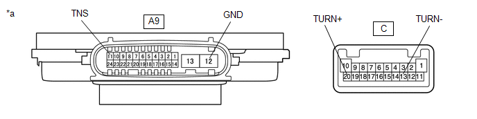
(a) Remove the headlight ECU sub-assembly RH. Click here
(b) Measure the resistance according to the value(s) in the table below. Standard Resistance:
(a) Disconnect the G15 combination meter assembly connector. (b) Disconnect the I12 outer rear view mirror sub-assembly RH*1 connector. (c) Disconnect the I13 outer rear view mirror sub-assembly RH*2 connector. (d) Measure the resistance according to the value(s) in the table below. Standard Resistance:
(a) Disconnect the P9 rear combination light assembly RH connector. (b) Operate the headlight dimmer switch assembly and check that the RH side turn signal lights other than the rear turn signal light blink. HINT: If the RH side turn signal lights blink, the rear combination light assembly RH is malfunctioning.
(a) Interchange the rear combination light socket and wire RH with LH and connect the connectors. Click here (b) Check that the rear turn signal light operates normally. OK: Rear turn signal light blinks.
(a) Disconnect the G15 combination meter assembly connector. (b) Measure the resistance according to the value(s) in the table below. Standard Resistance:
(a) Connect the P9 rear combination light assembly RH connector. (b) Connect the G15 combination meter assembly connector. (c) Disconnect the I13 outer rear view mirror sub-assembly RH connector. (d) Operate the headlight dimmer switch assembly and check that the RH side turn signal lights other than the side turn signal light blink. HINT: If the RH side turn signal lights blink, the outer rear view mirror sub-assembly RH is malfunctioning.
(a) Remove the side turn signal light assembly RH. Click here
(b) Inspect the side turn signal light assembly RH. Click here
(a) Connect the I13 outer rear view mirror sub-assembly RH connector. (b) Disconnect the A44 headlight assembly RH connector. (c) Operate the headlight dimmer switch assembly and check that the RH side turn signal lights other than the headlight turn signal light blink. HINT: If the RH side turn signal lights blink, the headlight assembly RH is malfunctioning.
(a) Disconnect the G15 combination meter assembly connector. (b) Disconnect the I13 outer rear view mirror sub-assembly RH connector. (c) Measure the resistance according to the value(s) in the table below. Standard Resistance:
|
Toyota Avalon (XX50) 2019-2022 Service & Repair Manual > Smart Key System(for Start Function, Gasoline Model): ACC Monitor Malfunction (B2274)
DESCRIPTION This DTC is stored when a malfunction in the ACC output circuit is detected. The ACC output circuit is the circuit between terminal ACCD of the certification ECU (smart key ECU assembly) and the ACC relay. DTC No. Detection Item DTC Detection Condition Trouble Area Note B2274 ACC Monitor ...


