ACN CALL END
ACN CALL END
This function terminates the ACN (Automatic Collision Notification) to the telematics provider. After a collision in which the DCM receives "Collision Detection Signal", the vehicle will send the emergency call notification to the telematics provider until the ACN call end utility has been run, or the BUB (Back-Up Battery) (if equipped) is depleted. Use the ACN Call End utility to stop the ACN call.
NOTICE:
The BUB (Back-Up Battery) must not be replaced while an ACN call is in progress.
HINT:
After the ACN call end utility has been completed, the BUB (Back-Up Battery) must be replaced.
(a) Connect the Techstream to the DLC3.
(b) Turn the engine switch on (IG).
(c) Turn the Techstream on.
(d) Choose "Telematics" from the System Selection Menu, and then click "Utility".
(e) Click "DCM Service" on the Utility Selection Menu.
Body Electrical > Telematics > Utility|
Tester Display |
|---|
| DCM Service |
(f) Choose "ACN call end" and then click "Next" on the DCM Service Utility.

|
*a | Example |
(g) Follow the instructions on the Techstream.
DESCRIPTION
This DTC is set when an error in the EEPROM or PLL IC is detected on the DCM (Telematics Transceiver) self-check. The EEPROM (Electrically Erasable Programmable Read-Only Memory) stores the various data to operate the safety connect system. The PLL IC (Phase-Locked Loop Integrated Circuit) oscillates telephone radio frequency.
|
DTC No. | Detection Item |
DTC Detection Condition | Trouble Area |
|---|---|---|---|
|
B15A8 | Telematics Transceiver Malfunction |
Error in EEPROM or PLL IC is detected. |
DCM (Telematics Transceiver) |
CAUTION / NOTICE / HINT
NOTICE:
Regardless of whether DTC B15A8 has been output as a present or history DTC, the DCM (Telematics Transceiver) should be replaced.
PROCEDURE
| 1. |
REPLACE DCM (TELEMATICS TRANSCEIVER) |
(a) Replace the DCM (Telematics Transceiver).
Click here 
NOTICE:
| NEXT |  | PERFORM DCM ACTIVATION |
DESCRIPTION
These DTCs are stored when the DCM (Telematics Transceiver) detects an open or a short in the telephone and GPS antenna assembly (for Roof Side) circuit. The DCM (Telematics Transceiver) receives 1574.42 - 1576.42 MHz radio frequency signals from satellites through the telephone and GPS antenna assembly (for Roof Side). The cable is a 50 Ω coaxial cable.
|
DTC No. | Detection Item |
DTC Detection Condition | Trouble Area |
|---|---|---|---|
|
B15C0 | Short in GPS Antenna |
Current for telephone and GPS antenna assembly (for Roof Side) is lower (Ω) malfunction criterion for 10 seconds when engine switch is on (IG). (Short circuit) |
|
| B15C1 |
Open in GPS Antenna | Current for telephone and GPS antenna assembly (for Roof Side) is higher (Ω) malfunction criterion for 10 seconds when engine switch is on (IG). (Open circuit) |
|
WIRING DIAGRAM

CAUTION / NOTICE / HINT
HINT:
Click here 
Click here
PROCEDURE
|
1. | CHECK DTC |
(a) Turn the engine switch off.
(b) Connect the Techstream to the DLC3.
(c) Turn the engine switch on (IG) and wait for 10 seconds.
(d) Turn the Techstream on.
(e) Clear the DTCs.
Body Electrical > Telematics > Clear DTCs(f) Recheck for DTCs.
Body Electrical > Telematics > Trouble Codes|
Result | Proceed to |
|---|---|
|
DTC B15C0 or B15C1 is output |
A |
| DTC B15C0 or B15C1 is not output |
B |
| B |
 | CHECK FOR INTERMITTENT PROBLEMS |
|
| 2. |
INSPECT TELEPHONE AND GPS ANTENNA CORD (NO. 6 ANTENNA CORD SUB-ASSEMBLY) |
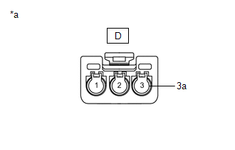
| (a) Disconnect the D telephone and GPS antenna cord (No. 6 antenna cord sub-assembly) connector. |
|
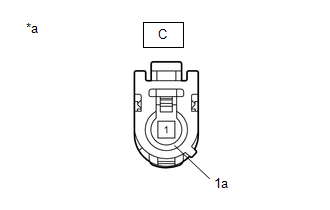
| (b) Disconnect the C telephone and GPS antenna cord (No. 6 antenna cord sub-assembly) connector. |
|
(c) Measure the resistance according to the value(s) in the table below.
Standard Resistance:
|
Tester Connection | Condition |
Specified Condition |
|---|---|---|
|
D-2 - C-1 | Always |
Below 1 Ω |
|
D-2 or C-1 - Body ground |
Always | 10 kΩ or higher |
|
D-2a - C-1a | Always |
Below 1 Ω |
|
D-2a or C-1a - Body ground |
Always | 10 kΩ or higher |
| NG | | REPLACE TELEPHONE AND GPS ANTENNA CORD (NO. 6 ANTENNA CORD SUB-ASSEMBLY) |
|
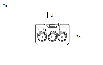
| 3. |
INSPECT TELEPHONE AND GPS ANTENNA CORD (NO. 4 ANTENNA CORD SUB-ASSEMBLY) |
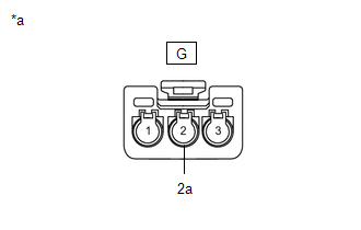
| (a) Disconnect the G telephone and GPS antenna cord (No. 4 antenna cord sub-assembly) connector. |
|
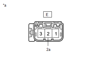
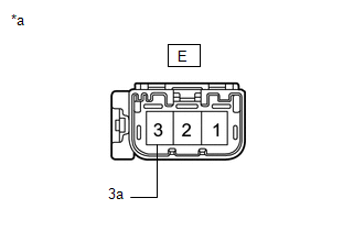
| (b) Disconnect the E telephone and GPS antenna cord (No. 4 antenna cord sub-assembly) connector. |
|
(c) Measure the resistance according to the value(s) in the table below.
Standard Resistance:
|
Tester Connection | Condition |
Specified Condition |
|---|---|---|
|
G-2 - E-2 | Always |
Below 1 Ω |
|
G-2 or E-2 - Body ground |
Always | 10 kΩ or higher |
|
G-2a - E-2a | Always |
Below 1 Ω |
|
G-2a or E-2a - Body ground |
Always | 10 kΩ or higher |
| NG | | REPLACE TELEPHONE AND GPS ANTENNA CORD (NO. 4 ANTENNA CORD SUB-ASSEMBLY) |
|
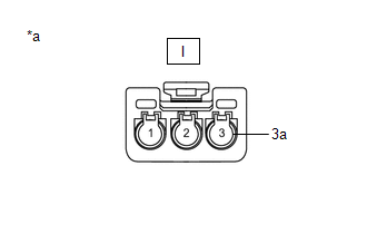
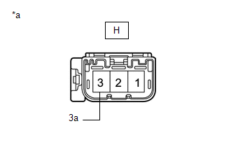
| 4. |
INSPECT TELEPHONE AND GPS ANTENNA CORD (NO. 3 ANTENNA CORD SUB-ASSEMBLY) |
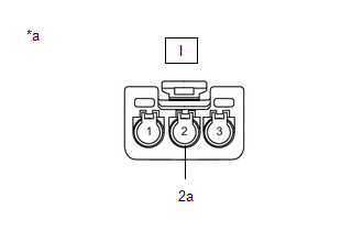
| (a) Disconnect the I telephone and GPS antenna cord (No. 3 antenna cord sub-assembly) connector. |
|
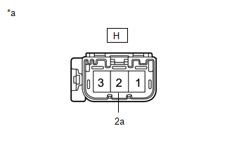
| (b) Disconnect the H telephone and GPS antenna cord (No. 3 antenna cord sub-assembly) connector. |
|
(c) Measure the resistance according to the value(s) in the table below.
Standard Resistance:
|
Tester Connection | Condition |
Specified Condition |
|---|---|---|
|
I-2 - H-2 | Always |
Below 1 Ω |
|
I-2 or H-2 - Body ground |
Always | 10 kΩ or higher |
|
I-2a - H-2a | Always |
Below 1 Ω |
|
I-2a or H-2a - Body ground |
Always | 10 kΩ or higher |
| NG | | REPLACE TELEPHONE AND GPS ANTENNA CORD (NO. 3 ANTENNA CORD SUB-ASSEMBLY) |
|
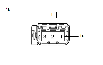
| 5. |
INSPECT TELEPHONE AND GPS ANTENNA CORD (NO. 2 ANTENNA CORD SUB-ASSEMBLY) |
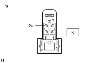
| (a) Disconnect the K telephone and GPS antenna cord (No. 2 antenna cord sub-assembly) connector. |
|
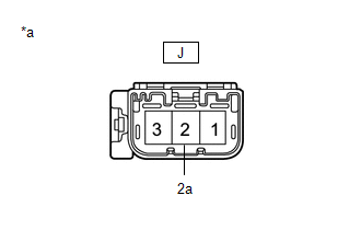
| (b) Disconnect the J telephone and GPS antenna cord (No. 2 antenna cord sub-assembly) connector. |
|
(c) Measure the resistance according to the value(s) in the table below.
Standard Resistance:
|
Tester Connection | Condition |
Specified Condition |
|---|---|---|
|
K-2 - J-2 | Always |
Below 1 Ω |
|
K-2 or J-2 - Body ground |
Always | 10 kΩ or higher |
|
K-2a - J-2a | Always |
Below 1 Ω |
|
K-2a or J-2a - Body ground |
Always | 10 kΩ or higher |
| NG | | REPLACE TELEPHONE AND GPS ANTENNA CORD (NO. 2 ANTENNA CORD SUB-ASSEMBLY) |
|
| 6. |
REPLACE TELEPHONE AND GPS ANTENNA ASSEMBLY (for Roof Side) |
(a) Replace the telephone and GPS antenna assembly (for Roof Side) with a known good one and check if the same problem occurs again.
Click here
OK:
The system returns to normal.
| OK | | END |
|
| 7. |
REPLACE DCM (TELEMATICS TRANSCEIVER) |
(a) Replace the DCM (Telematics Transceiver).
Click here
NOTICE:
| NEXT | | PERFORM DCM ACTIVATION |
DESCRIPTION
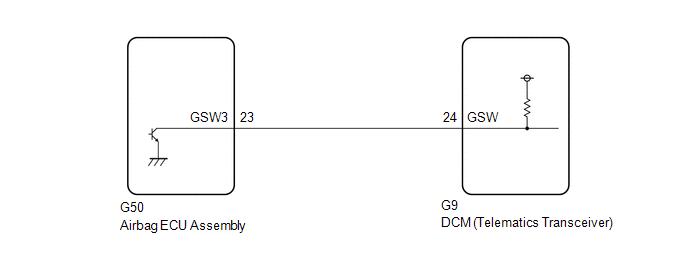
If the DCM (Telematics Transceiver) detects an error in communication between the DCM (Telematics Transceiver) and the airbag ECU assembly as a result of the DCM (Telematics Transceiver) self check, this DTC will be set.
|
DTC No. | Detection Item |
DTC Detection Condition | Trouble Area |
|---|---|---|---|
|
B15C4 | Airbag Signal Malfunction/Not Input |
DCM (Telematics Transceiver) detects an error in signals from airbag ECU assembly when engine switch is on (IG). |
|
WIRING DIAGRAM
CAUTION / NOTICE / HINT
NOTICE:
The vehicle is equipped with an SRS (Supplemental Restraint System) which includes components such as airbags. Before servicing (including removal or installation of parts), be sure to read the Precaution in the SRS.
Click here

PROCEDURE
| 1. |
CHECK DTC (AIRBAG SYSTEM) |
(a) Turn the engine switch off.
(b) Connect the Techstream to the DLC3.
(c) Turn the engine switch on (IG) and wait for 10 seconds.
(d) Turn the Techstream on.
(e) Clear the DTCs.
Body Electrical > SRS Airbag > Clear DTCs(f) Recheck for DTCs.
Body Electrical > SRS Airbag > Trouble Codes|
Result | Proceed to |
|---|---|
|
DTCs are not output | A |
|
DTCs are output | B |
| B |
 | GO TO AIRBAG SYSTEM |
|
| 2. |
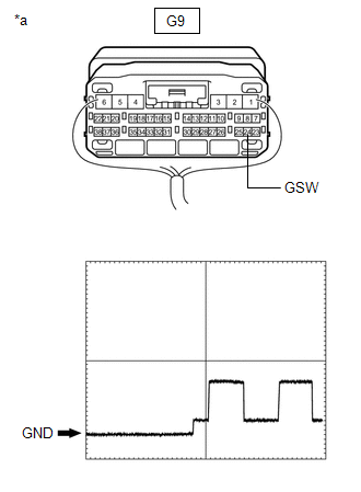
INSPECT DCM (TELEMATICS TRANSCEIVER) (GSW SIGNAL) |
| (a) Remove the DCM (Telematics Transceiver) but do not disconnect the connectors. Click here |
|
(b) Measure the voltage according to the value(s) in the table below.
Standard Voltage:
|
Tester Connection | Condition |
Specified Condition |
|---|---|---|
|
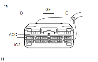
G9-24 (GSW) - Body ground |
Engine switch on (IG) |
6.5 to 8.5 V |
Reference Waveform:
|
Item | Condition |
|---|---|
|
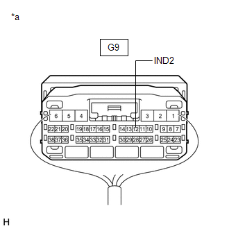
Tester connection | G9-24 (GSW) - Body ground |
|
Tool setting | 5.0 V/DIV., 20 ms/DIV. |
|
Vehicle condition | Engine switch on (IG) |
|
Result | Proceed to |
|---|---|
|
8.5 V or higher | A |
|
Below 6.5 V | B |
|
6.5 to 8.5 V | C |
| B |
| GO TO STEP 4 |
| C |
| GO TO STEP 5 |
|
| 3. |
CHECK HARNESS AND CONNECTOR (FOR OPEN CIRCUIT) |
(a) Remove the airbag ECU assembly but do not disconnect the connectors.
Click here
| (b) Measure the voltage according to the value(s) in the table below. Standard Voltage:
Reference Waveform:
|
|
| OK | | REPLACE AIRBAG ECU ASSEMBLY |
| NG | | REPAIR OR REPLACE HARNESS OR CONNECTOR |
| 4. |
CHECK HARNESS AND CONNECTOR (FOR SHORT CIRCUIT) |
(a) Disconnect the G9 DCM (Telematics Transceiver) connector.
(b) Measure the resistance according to the value(s) in the table below.
Standard Resistance:
|
Tester Connection | Condition |
Specified Condition |
|---|---|---|
|
G9-24 (GSW) - Body ground |
Always | 10 kΩ or higher |
|
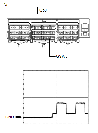
G50-23 (GSW3) - Body ground |
Always | 10 kΩ or higher |
| NG | | GO TO STEP 6 |
|
| 5. |
REPLACE DCM (TELEMATICS TRANSCEIVER) |
(a) Replace the DCM (Telematics Transceiver).
Click here
NOTICE:
| NEXT | | PERFORM DCM ACTIVATION |
| 6. |
CHECK HARNESS AND CONNECTOR (DCM (TELEMATICS TRANSCEIVER) - AIRBAG ECU ASSEMBLY) |
(a) Disconnect the G9 DCM (Telematics Transceiver) connector.
(b) Disconnect the G50 airbag ECU assembly connector.
(c) Measure the resistance according to the value(s) in the table below.
Standard Resistance:
|
Tester Connection | Condition |
Specified Condition |
|---|---|---|
|
G9-24 (GSW) - G50-23 (GSW3) |
Always | Below 1 Ω |
|
G9-24 (GSW) or G50-23 (GSW3) - Body ground |
Always | 10 kΩ or higher |
| OK | | REPLACE AIRBAG ECU ASSEMBLY |
| NG | | REPAIR OR REPLACE HARNESS OR CONNECTOR |
DESCRIPTION
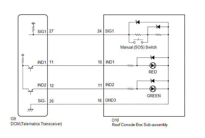
This DTC is set when the DCM (Telematics Transceiver) detects an open or short circuit in the manual (SOS) switch.
|
DTC No. | Detection Item |
DTC Detection Condition | Trouble Area |
|---|---|---|---|
|
B15C5 | Manual Button Malfunction |
Open or short circuit in manual (SOS) switch is detected. |
|
WIRING DIAGRAM
w/o Sliding Roof w/ Sliding Roof

CAUTION / NOTICE / HINT
HINT:
Before performing this diagnostic procedure, make sure to perform Health Check and confirm that the DCM/VIN registration information is correct.
Click here

PROCEDURE
| 1. |
CONFIRM MODEL |
(a) Choose the model to be inspected.
| Result |
Proceed to |
|---|---|
| w/ Sliding Roof |
A |
| w/o Sliding Roof |
B |
| B |
 | GO TO STEP 6 |
|
| 2. |
CHECK DTC |
(a) Turn the engine switch off.
(b) Connect the Techstream to the DLC3.
(c) Turn the engine switch on (IG) and wait for 10 seconds.
(d) Turn the Techstream on.
(e) Clear the DTCs.
Body Electrical > Telematics > Clear DTCs(f) Recheck for DTCs.
Body Electrical > Telematics > Trouble Codes|
Result | Proceed to |
|---|---|
|
DTC B1570, B1571 and B15C5 are output |
A |
| DTC B15C5 is output (DTC B1570 and B1571 are not output) |
B |
| B |
| USE SIMULATION METHOD TO CHECK |
|
| 3. |
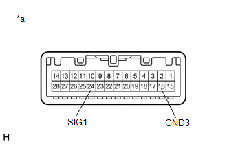
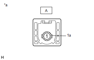
INSPECT ROOF CONSOLE BOX SUB-ASSEMBLY (MANUAL (SOS) SWITCH) |
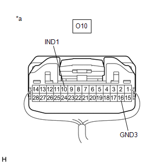
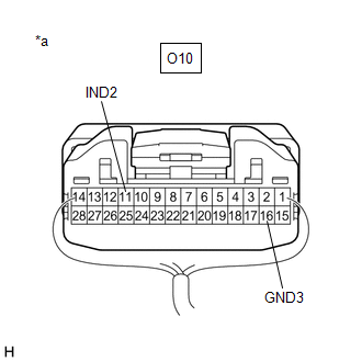
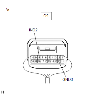
| (a) Disconnect the O10 roof console box sub-assembly connector. |
|
(b) Measure the resistance according to the value(s) in the table below.
Standard Resistance:
|
Tester Connection | Condition |
Specified Condition |
|---|---|---|
|
24 (SIG1) - 16 (GND3) |
Manual (SOS) switch not pressed |
410 to 414 Ω |
|
24 (SIG1) - 16 (GND3) |
Manual (SOS) switch pressed |
81 to 83 Ω |
| NG | | REPLACE ROOF CONSOLE BOX SUB-ASSEMBLY |
|
| 4. |
CHECK HARNESS AND CONNECTOR (DCM (TELEMATICS TRANSCEIVER) - ROOF CONSOLE BOX SUB-ASSEMBLY) |
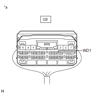
(a) Disconnect the G9 DCM (Telematics Transceiver) connector.
(b) Disconnect the O10 roof console box sub-assembly connector.
(c) Measure the resistance according to the value(s) in the table below.
Standard Resistance:
|
Tester Connection | Condition |
Specified Condition |
|---|---|---|
|
G9-26 (SIG-) - O10-16 (GND3) |
Always | Below 1 Ω |
|
G9-26 (SIG-) or O10-16 (GND3) - Body ground |
Always | 10 kΩ or higher |
|
G9-27 (SIG1) - O10-24 (SIG1) |
Always | Below 1 Ω |
|
G9-27 (SIG1) or O10-24 (SIG1) - Body ground |
Always | 10 kΩ or higher |
| NG | | REPAIR OR REPLACE HARNESS OR CONNECTOR |
|
| 5. |
REPLACE DCM (TELEMATICS TRANSCEIVER) |
(a) Replace the DCM (Telematics Transceiver).
Click here
NOTICE:
| NEXT | | PERFORM DCM ACTIVATION |
| 6. |
CHECK DTC |
(a) Turn the engine switch off.
(b) Connect the Techstream to the DLC3.
(c) Turn the engine switch on (IG) and wait for 10 seconds.
(d) Turn the Techstream on.
(e) Clear the DTCs.
Body Electrical > Telematics > Clear DTCs(f) Recheck for DTCs.
Body Electrical > Telematics > Trouble Codes|
Result | Proceed to |
|---|---|
|
DTC B1570, B1571 and B15C5 are output |
A |
| DTC B15C5 is output (DTC B1570 and B1571 are not output) |
B |
| B |
| USE SIMULATION METHOD TO CHECK |
|
| 7. |
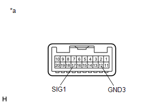
INSPECT ROOF CONSOLE BOX SUB-ASSEMBLY (MANUAL (SOS) SWITCH) |
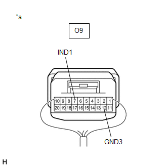
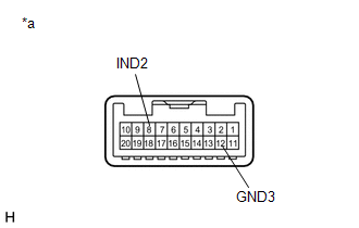
| (a) Disconnect the O9 roof console box sub-assembly connector. |
|
(b) Measure the resistance according to the value(s) in the table below.
Standard Resistance:
|
Tester Connection | Condition |
Specified Condition |
|---|---|---|
|
17 (SIG1) - 12 (GND3) |
Manual (SOS) switch not pressed |
410 to 414 Ω |
|
17 (SIG1) - 12 (GND3) |
Manual (SOS) switch pressed |
81 to 83 Ω |
| NG | | REPLACE ROOF CONSOLE BOX SUB-ASSEMBLY |
|
| 8. |
CHECK HARNESS AND CONNECTOR (DCM (TELEMATICS TRANSCEIVER) - ROOF CONSOLE BOX SUB-ASSEMBLY) |
(a) Disconnect the G9 DCM (Telematics Transceiver) connector.
(b) Disconnect the O9 roof console box sub-assembly connector.
(c) Measure the resistance according to the value(s) in the table below.
Standard Resistance:
|
Tester Connection | Condition |
Specified Condition |
|---|---|---|
|
G9-26 (SIG-) - O9-12 (GND3) |
Always | Below 1 Ω |
|
G9-26 (SIG-) or O9-12 (GND3) - Body ground |
Always | 10 kΩ or higher |
|
G9-27 (SIG1) - O9-17 (SIG1) |
Always | Below 1 Ω |
|
G9-27 (SIG1) or O9-17 (SIG1) - Body ground |
Always | 10 kΩ or higher |
| NG | | REPAIR OR REPLACE HARNESS OR CONNECTOR |
|
| 9. |
REPLACE DCM (TELEMATICS TRANSCEIVER) |
(a) Replace the DCM (Telematics Transceiver).
Click here
NOTICE:
| NEXT | | PERFORM DCM ACTIVATION |
DESCRIPTION
This DTC is set when the DCM (Telematics Transceiver) detects one of the following:
|
DTC No. | Detection Item |
DTC Detection Condition | Trouble Area |
|---|---|---|---|
|
B15CC | Backup Battery Failure |
BUB (Back-Up Battery) malfunction |
|
CAUTION / NOTICE / HINT
HINT:
Before performing this diagnostic procedure, make sure to perform Health Check and confirm that the DCM/VIN registration information is correct.
Click here

PROCEDURE
| 1. |
CHECK DTC |
(a) Turn the engine switch off.
(b) Connect the Techstream to the DLC3.
(c) Turn the engine switch on (IG) and wait for 10 seconds.
(d) Turn the Techstream on.
(e) Clear the DTCs.
Body Electrical > Telematics > Clear DTCs(f) Recheck for DTCs.
Body Electrical > Telematics > Trouble Codes|
Result | Proceed to |
|---|---|
|
DTC B15CC is output | A |
|
DTC B15CC is not output |
B |
| B |
 | CHECK FOR INTERMITTENT PROBLEMS |
|
| 2. |
REPLACE BUB (BACK-UP BATTERY) |
(a) Replace the BUB (Back-Up Battery) with a known good one and check if the same problem occurs again.
Click here
NOTICE:
The BUB (Back-Up Battery) must not be replaced while an ACN call is in progress.
Click here
|
| 3. |
CLEAR DTC |
(a) Clear the DTCs.
Click here
|
| 4. |
RECHECK DTC |
(a) Recheck for DTCs and check if the same trouble occurs again.
Click here
OK:
No DTC is output.
| OK | | END |
|
| 5. |
REPLACE DCM (TELEMATICS TRANSCEIVER) |
(a) Replace the DCM (Telematics Transceiver).
Click here
NOTICE:
| NEXT | | PERFORM DCM ACTIVATION |
DESCRIPTION
This DTC is set when the DCM (Telematics Transceiver) detects either of the following conditions.
When this DTC is set, the BUB (Back-Up Battery) must be replaced.
BUB (Back-Up Battery) degradation DTC B15EC is not reported in deactive mode.
|
DTC No. | Detection Item |
DTC Detection Condition | Trouble Area |
|---|---|---|---|
|
B15EC | Backup Battery Degradation |
BUB (Back-Up Battery) is used up. |
BUB (Back-Up Battery) |
CAUTION / NOTICE / HINT
NOTICE:
Click here 
HINT:
Before performing this diagnostic procedure, make sure to perform Health Check and confirm that the DCM/VIN registration information is correct.
Click here
PROCEDURE
| 1. |
CHECK DTC |
(a) Turn the engine switch off.
(b) Connect the Techstream to the DLC3.
(c) Turn the engine switch on (IG) and wait for 10 seconds.
(d) Turn the Techstream on.
(e) Clear the DTCs.
Body Electrical > Telematics > Clear DTCs(f) Recheck for DTCs.
Body Electrical > Telematics > Trouble Codes|
Result | Proceed to |
|---|---|
|
DTC B15EC is output | A |
|
DTC B15EC is not output |
B |
| A |
 | REPLACE BUB (BACK-UP BATTERY) |
| B |
| CHECK FOR INTERMITTENT PROBLEMS |
DESCRIPTION
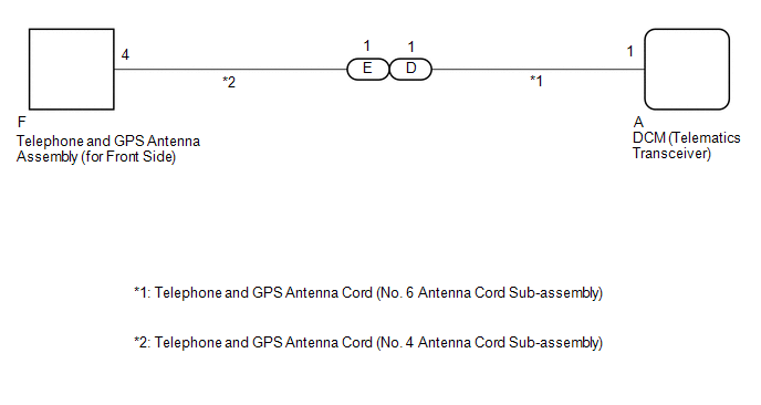
These DTCs are stored when the DCM (Telematics Transceiver) detects an open or a short in the telephone and GPS antenna assembly (for Front Side) circuit. The DCM (Telematics Transceiver) oscillates and receives 824 - 894 MHz or 1850 - 1990 MHz radio-frequency through the telephone and GPS antenna assembly (for Front Side).
|
DTC No. | Detection Item |
DTC Detection Condition | Trouble Area |
|---|---|---|---|
|
B1536 | Short in Telephone SUB Antenna Circuit |
Telephone and GPS antenna assembly (for Front Side) impedance is lower than malfunction criterion for 10 seconds when engine switch is on (IG). (Short circuit) |
|
| B1537 |
Open in Telephone SUB Antenna Circuit |
Telephone and GPS antenna assembly (for Front Side) impedance is higher than malfunction criterion for 10 seconds when engine switch is on (IG). (Open circuit) |
|
WIRING DIAGRAM
CAUTION / NOTICE / HINT
HINT:
Click here 
Click here
PROCEDURE
|
1. | CHECK DTC |
(a) Turn the engine switch off.
(b) Connect the Techstream to the DLC3.
(c) Turn the engine switch on (IG) and wait for 10 seconds.
(d) Turn the Techstream on.
(e) Clear the DTCs.
Body Electrical > Telematics > Clear DTCs(f) Recheck for DTCs.
Body Electrical > Telematics > Trouble Codes|
Result | Proceed to |
|---|---|
|
DTC B1536 or B1537 is output |
A |
| DTC B1536 or B1537 is not output |
B |
| B |
 | CHECK FOR INTERMITTENT PROBLEMS |
|
| 2. |
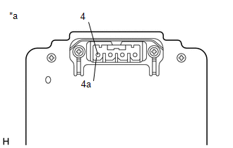
INSPECT TELEPHONE AND GPS ANTENNA ASSEMBLY (for Front Side) |
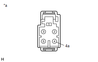
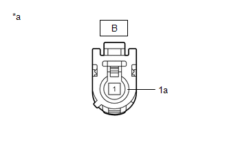
| (a) Disconnect the telephone and GPS antenna assembly (for Front Side) connector. |
|
(b) Measure the resistance according to the value(s) in the table below.
Standard Resistance:
|
Tester Connection | Condition |
Specified Condition |
|---|---|---|
|
4 - 4a | Always |
4 to 11 kΩ |
| NG | | REPLACE TELEPHONE AND GPS ANTENNA ASSEMBLY (for Front Side) |
|
| 3. |
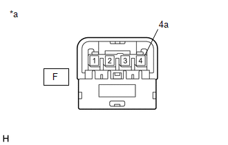
INSPECT TELEPHONE AND GPS ANTENNA CORD (NO. 4 ANTENNA CORD SUB-ASSEMBLY) |
| (a) Disconnect the F telephone and GPS antenna cord (No. 4 antenna cord sub-assembly) connector. |
|
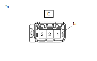
| (b) Disconnect the E telephone and GPS antenna cord (No. 4 antenna cord sub-assembly) connector. |
|
(c) Measure the resistance according to the value(s) in the table below.
Standard Resistance:
|
Tester Connection | Condition |
Specified Condition |
|---|---|---|
|
F-4 - E-3 | Always |
Below 1 Ω |
|
F-4 or E-3 - Body ground |
Always | 10 kΩ or higher |
|
F-4a - E-3a | Always |
Below 1 Ω |
|
F-4a or E-3a - Body ground |
Always | 10 kΩ or higher |
| NG | | REPLACE TELEPHONE AND GPS ANTENNA CORD (NO. 4 ANTENNA CORD SUB-ASSEMBLY) |
|
| 4. |
INSPECT TELEPHONE AND GPS ANTENNA CORD (NO. 6 ANTENNA CORD SUB-ASSEMBLY) |
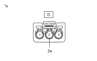
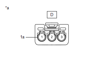
| (a) Disconnect the D telephone and GPS antenna cord (No. 6 antenna cord sub-assembly) connector. |
|
| (b) Disconnect the A telephone and GPS antenna cord (No. 6 antenna cord sub-assembly) connector. |
|
(c) Measure the resistance according to the value(s) in the table below.
Standard Resistance:
|
Tester Connection | Condition |
Specified Condition |
|---|---|---|
|
D-1 - A-1 | Always |
Below 1 Ω |
|
D-1 or A-1 - Body ground |
Always | 10 kΩ or higher |
|
D-1a - A-1a | Always |
Below 1 Ω |
|
D-1a or A-1a - Body ground |
Always | 10 kΩ or higher |
| NG | | REPLACE TELEPHONE AND GPS ANTENNA CORD (NO. 6 ANTENNA CORD SUB-ASSEMBLY) |
|
| 5. |
REPLACE TELEPHONE AND GPS ANTENNA ASSEMBLY (for Front Side) |
(a) Replace the telephone and GPS antenna assembly (for Front Side) with a known good one and check if the same problem occurs again.
Click here
OK:
The system returns to normal.
| OK | | END |
|
| 6. |
REPLACE DCM (TELEMATICS TRANSCEIVER) |
(a) Replace the DCM (Telematics Transceiver).
Click here
NOTICE:
| NEXT | | PERFORM DCM ACTIVATION |
DESCRIPTION
This DTC is stored when the DCM (Telematics Transceiver) detects an open or short in the manual (SOS) switch red indicator circuit of the manual (SOS) switch.
The manual (SOS) switch red indicator illuminates for 2 seconds and goes off when the engine switch is turned on (IG). If a malfunction in the safety connect system is detected, the manual (SOS) switch red indicator will illuminate.
However, the manual (SOS) switch red indicator may not illuminate when this DTC is set.
|
DTC No. | Detection Item |
DTC Detection Condition | Trouble Area |
|---|---|---|---|
|
B1570 | Manual (SOS) Switch Red Indicator Malfunction |
Current for manual (SOS) switch red indicator reaches malfunction criteria for 10 seconds when engine switch is on (IG). |
|
WIRING DIAGRAM
w/o Sliding Roof w/ Sliding Roof

CAUTION / NOTICE / HINT
HINT:
Click here 
PROCEDURE
|
1. | CONFIRM MODEL |
(a) Choose the model to be inspected.
| Result |
Proceed to |
|---|---|
| w/ Sliding Roof |
A |
| w/o Sliding Roof |
B |
| B |
 | GO TO STEP 10 |
|
| 2. |
CHECK DTC |
(a) Turn the engine switch off.
(b) Connect the Techstream to the DLC3.
(c) Turn the engine switch on (IG) and wait for 10 seconds.
(d) Turn the Techstream on.
(e) Clear the DTCs.
Body Electrical > Telematics > Clear DTCs(f) Recheck for DTCs.
Body Electrical > Telematics > Trouble Codes|
Result | Proceed to |
|---|---|
|
DTC B1570, B1571 and B15C5 are output |
A |
| DTC B1570 is output (DTC B1571 and B15C5 are not output) |
B |
| B |
| GO TO STEP 6 |
|
| 3. |
INSPECT ROOF CONSOLE BOX SUB-ASSEMBLY (RED INDICATOR) |
| (a) Disconnect the O10 roof console box sub-assembly connector. |
|
(b) Connect 2 dry-cell batteries (1.5 V each) in series.
(c) Connect the positive (+) lead to terminal 10 (IND1) and the negative (-) lead to terminal 16 (GND3) of the roof console box sub-assembly connector.
(d) Check if the illumination for the manual (SOS) switch red indicator comes on.
OK:
Red indicator comes on.
| NG | | REPLACE ROOF CONSOLE BOX SUB-ASSEMBLY |
|
| 4. |
CHECK HARNESS AND CONNECTOR (DCM (TELEMATICS TRANSCEIVER) - ROOF CONSOLE BOX SUB-ASSEMBLY) |
(a) Disconnect the G9 DCM (Telematics Transceiver) connector.
(b) Disconnect the O10 roof console box sub-assembly connector.
(c) Measure the resistance according to the value(s) in the table below.
Standard Resistance:
|
Tester Connection | Condition |
Specified Condition |
|---|---|---|
|
G9-26 (SIG-) - O10-16 (GND3) |
Always | Below 1 Ω |
|
G9-26 (SIG-) or O10-16 (GND3) - Body ground |
Always | 10 kΩ or higher |
|
G9-11 (IND1) - O10-10 (IND1) |
Always | Below 1 Ω |
|
G9-11 (IND1) or O10-10 (IND1) - Body ground |
Always | 10 kΩ or higher |
| NG | | REPAIR OR REPLACE HARNESS OR CONNECTOR |
|
| 5. |
REPLACE DCM (TELEMATICS TRANSCEIVER) |
(a) Replace the DCM (Telematics Transceiver).
Click here
NOTICE:
| NEXT | | PERFORM DCM ACTIVATION |
| 6. |
CHECK ROOF CONSOLE BOX SUB-ASSEMBLY (MANUAL (SOS) SWITCH RED INDICATOR CONDITION) |
(a) Confirm the red indicator status after the engine switch is turned on (IG).
Click here
|
Result | Proceed to |
|---|---|
|
Red indicator remains off |
A |
| Red indicator remains on |
B |
| B |
| GO TO STEP 19 |
|
| 7. |
INSPECT ROOF CONSOLE BOX SUB-ASSEMBLY (RED INDICATOR INPUT VOLTAGE) |
| (a) Remove the roof console box sub-assembly but do not disconnect the connectors. Click here |
|
(b) Connect the positive lead of a voltmeter to terminal O10-10 (IND1), and the negative lead to terminal O10-16 (GND3).
(c) Measure the voltage.
Standard:
1.0 to 8.5 V for 2 seconds after the engine switch is turned on (IG).
0 V when the engine switch is off.
| OK | | REPLACE ROOF CONSOLE BOX SUB-ASSEMBLY |
|
| 8. |
INSPECT DCM (TELEMATICS TRANSCEIVER) (RED INDICATOR OUTPUT VOLTAGE) |
| (a) Remove the DCM (Telematics Transceiver) but do not disconnect the connectors. Click here |
|
(b) Connect the positive lead of a voltmeter to terminal G9-11 (IND1), and the negative lead to body ground.
(c) Measure the voltage.
Standard:
1.0 to 8.5 V for 2 seconds after the engine switch is turned on (IG).
0 V when the engine switch is off.
| OK | | REPAIR OR REPLACE HARNESS OR CONNECTOR |
|
| 9. |
CHECK HARNESS AND CONNECTOR (DCM (TELEMATICS TRANSCEIVER) - BODY GROUND) |
| (a) Remove the DCM (Telematics Transceiver) but do not disconnect the connectors. Click here |
|
(b) Measure the resistance according to the value(s) in the table below.
Standard Resistance:
|
Tester Connection | Condition |
Specified Condition |
|---|---|---|
|
G9-11 (IND1) - Body ground |
Always | 10 kΩ or higher |
| OK | | GO TO STEP 19 |
| NG | | REPAIR OR REPLACE HARNESS OR CONNECTOR |
| 10. |
CHECK DTC |
(a) Turn the engine switch off.
(b) Connect the Techstream to the DLC3.
(c) Turn the engine switch on (IG) and wait for 10 seconds.
(d) Turn the Techstream on.
(e) Clear the DTCs.
Body Electrical > Telematics > Clear DTCs(f) Recheck for DTCs.
Body Electrical > Telematics > Trouble Codes|
Result | Proceed to |
|---|---|
|
DTC B1570, B1571 and B15C5 are output |
A |
| DTC B1570 is output (DTC B1571 and B15C5 are not output) |
B |
| B |
| GO TO STEP 14 |
|
| 11. |
INSPECT ROOF CONSOLE BOX SUB-ASSEMBLY (RED INDICATOR) |
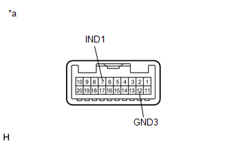
| (a) Disconnect the O9 roof console box sub-assembly connector. |
|
(b) Connect 2 dry-cell batteries (1.5 V each) in series.
(c) Connect the positive (+) lead to terminal 7 (IND1) and the negative (-) lead to terminal 12 (GND3) of the roof console box sub-assembly connector.
(d) Check if the illumination for the manual (SOS) switch red indicator comes on.
OK:
Red indicator comes on.
| NG | | REPLACE ROOF CONSOLE BOX SUB-ASSEMBLY |
|
| 12. |
CHECK HARNESS AND CONNECTOR (DCM (TELEMATICS TRANSCEIVER) - ROOF CONSOLE BOX SUB-ASSEMBLY) |
(a) Disconnect the G9 DCM (Telematics Transceiver) connector.
(b) Disconnect the O9 roof console box sub-assembly connector.
(c) Measure the resistance according to the value(s) in the table below.
Standard Resistance:
|
Tester Connection | Condition |
Specified Condition |
|---|---|---|
|
G9-26 (SIG-) - O9-12 (GND3) |
Always | Below 1 Ω |
|
G9-26 (SIG-) or O9-12 (GND3) - Body ground |
Always | 10 kΩ or higher |
|
G9-11 (IND1) - O9-7 (IND1) |
Always | Below 1 Ω |
|
G9-11 (IND1) or O9-7 (IND1) - Body ground |
Always | 10 kΩ or higher |
| NG | | REPAIR OR REPLACE HARNESS OR CONNECTOR |
|
| 13. |
REPLACE DCM (TELEMATICS TRANSCEIVER) |
(a) Replace the DCM (Telematics Transceiver).
Click here
NOTICE:
| NEXT | | PERFORM DCM ACTIVATION |
| 14. |
CHECK ROOF CONSOLE BOX SUB-ASSEMBLY (MANUAL (SOS) SWITCH RED INDICATOR CONDITION) |
(a) Confirm the red indicator status after the engine switch is turned on (IG).
Click here
|
Result | Proceed to |
|---|---|
|
Red indicator remains off |
A |
| Red indicator remains on |
B |
| B |
| GO TO STEP 19 |
|
| 15. |
INSPECT ROOF CONSOLE BOX SUB-ASSEMBLY (RED INDICATOR INPUT VOLTAGE) |
| (a) Remove the roof console box sub-assembly but do not disconnect the connectors. Click here |
|
(b) Connect the positive lead of a voltmeter to terminal O9-7 (IND1), and the negative lead to terminal O9-12 (GND3).
(c) Measure the voltage.
Standard:
1.0 to 8.5 V for 2 seconds after the engine switch is turned on (IG).
0 V when the engine switch is off.
| OK | | REPLACE ROOF CONSOLE BOX SUB-ASSEMBLY |
|
| 16. |
INSPECT DCM (TELEMATICS TRANSCEIVER) (RED INDICATOR OUTPUT VOLTAGE) |
| (a) Remove the DCM (Telematics Transceiver) but do not disconnect the connectors. Click here |
|
(b) Connect the positive lead of a voltmeter to terminal G9-11 (IND1), and the negative lead to body ground.
(c) Measure the voltage.
Standard:
1.0 to 8.5 V for 2 seconds after the engine switch is turned on (IG).
0 V when the engine switch is off.
| OK | | REPAIR OR REPLACE HARNESS OR CONNECTOR |
|
| 17. |
CHECK HARNESS AND CONNECTOR (DCM (TELEMATICS TRANSCEIVER) - BODY GROUND) |
| (a) Remove the DCM (Telematics Transceiver) but do not disconnect the connectors. Click here |
|
(b) Measure the resistance according to the value(s) in the table below.
Standard Resistance:
|
Tester Connection | Condition |
Specified Condition |
|---|---|---|
|
G9-11 (IND1) - Body ground |
Always | 10 kΩ or higher |
| NG | | REPAIR OR REPLACE HARNESS OR CONNECTOR |
|
| 18. |
REPLACE DCM (TELEMATICS TRANSCEIVER) |
(a) Replace the DCM (Telematics Transceiver).
Click here
NOTICE:
| NEXT | | PERFORM DCM ACTIVATION |
| 19. |
REPLACE DCM (TELEMATICS TRANSCEIVER) |
(a) Replace the DCM (Telematics Transceiver).
Click here
NOTICE:
| NEXT | | PERFORM DCM ACTIVATION |
DESCRIPTION
This DTC is set when the DCM (Telematics Transceiver) detects an open or short in the manual (SOS) switch green indicator circuit of the manual (SOS) switch. The manual (SOS) switch green indicator illuminates after the engine switch is turned on (IG).
If the safety connect system is not active, the manual (SOS) switch green indicator will turn off.
If the safety connect system is active, the manual (SOS) switch green indicator will blink while communicating with the call center.
|
DTC No. | Detection Item |
DTC Detection Condition | Trouble Area |
|---|---|---|---|
|
B1571 | Manual (SOS) Switch Green Indicator Malfunction |
Current for manual (SOS) switch green indicator reaches malfunction criteria for 10 seconds when engine switch is on (IG). |
|
WIRING DIAGRAM
w/o Sliding Roof w/ Sliding Roof
CAUTION / NOTICE / HINT
HINT:
Before performing this diagnostic procedure, make sure to perform Health Check and confirm that the DCM/VIN registration information is correct.
Click here

PROCEDURE
| 1. |
CONFIRM MODEL |
(a) Choose the model to be inspected.
| Result |
Proceed to |
|---|---|
| w/ Sliding Roof |
A |
| w/o Sliding Roof |
B |
| B |
 | GO TO STEP 11 |
|
| 2. |
CHECK DTC |
(a) Turn the engine switch off.
(b) Connect the Techstream to the DLC3.
(c) Turn the engine switch on (IG) and wait for 10 seconds.
(d) Turn the Techstream on.
(e) Clear the DTCs.
Body Electrical > Telematics > Clear DTCs(f) Recheck for DTCs.
Body Electrical > Telematics > Trouble Codes|
Result | Proceed to |
|---|---|
|
DTC B1570, B1571 and B15C5 are output |
A |
| DTC B1571 is output (DTC B1570 and B15C5 are not output) |
B |
| B |
| GO TO STEP 6 |
|
| 3. |
INSPECT ROOF CONSOLE BOX SUB-ASSEMBLY (GREEN INDICATOR) |
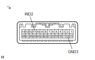
| (a) Disconnect the O10 roof console box sub-assembly connector. |
|
(b) Connect 2 dry-cell batteries (1.5 V each) in series.
(c) Connect the positive (+) lead to terminal 11 (IND2) and the negative (-) lead to terminal 16 (GND3) of the roof console box sub-assembly connector.
(d) Check if the illumination for the manual (SOS) switch green indicator comes on.
OK:
Green indicator comes on.
| NG | | REPLACE ROOF CONSOLE BOX SUB-ASSEMBLY |
|
| 4. |
CHECK HARNESS AND CONNECTOR (DCM (TELEMATICS TRANSCEIVER) - ROOF CONSOLE BOX SUB-ASSEMBLY) |
(a) Disconnect the G9 DCM (Telematics Transceiver) connector.
(b) Disconnect the O10 roof console box sub-assembly connector.
(c) Measure the resistance according to the value(s) in the table below.
Standard Resistance:
|
Tester Connection | Condition |
Specified Condition |
|---|---|---|
|
G9-26 (SIG-) - O10-16 (GND3) |
Always | Below 1 Ω |
|
G9-26 (SIG-) or O10-16 (GND3) - Body ground |
Always | 10 kΩ or higher |
|
G9-12 (IND2) - O10-11 (IND2) |
Always | Below 1 Ω |
|
G9-12 (IND2) or O10-11 (IND2) - Body ground |
Always | 10 kΩ or higher |
| NG | | REPAIR OR REPLACE HARNESS OR CONNECTOR |
|
| 5. |
REPLACE DCM (TELEMATICS TRANSCEIVER) |
(a) Replace the DCM (Telematics Transceiver).
Click here
NOTICE:
| NEXT | | PERFORM DCM ACTIVATION |
| 6. |
CHECK ROOF CONSOLE BOX SUB-ASSEMBLY (MANUAL (SOS) SWITCH GREEN INDICATOR CONDITION) |
(a) Confirm the green indicator status after the engine switch is turned on (IG).
Click here
|
Result | Proceed to |
|---|---|
|
Green indicator remains off |
A |
| Green indicator remains on |
B |
| B |
| GO TO STEP 10 |
|
| 7. |
INSPECT ROOF CONSOLE BOX SUB-ASSEMBLY (GREEN INDICATOR INPUT VOLTAGE) |
| (a) Remove the roof console box sub-assembly but do not disconnect the connectors. Click here |
|
(b) Connect the positive lead of a voltmeter to terminal O10-11 (IND2), and the negative lead to terminal O10-16 (GND3).
(c) Measure the voltage.
Standard:
1.0 to 8.5 V for 2 seconds after the engine switch is turned on (IG) and red indicator has turned off.
0 V when the engine switch is off.
| OK | | REPLACE ROOF CONSOLE BOX SUB-ASSEMBLY |
|
| 8. |
INSPECT DCM (TELEMATICS TRANSCEIVER) (GREEN INDICATOR OUTPUT VOLTAGE) |
| (a) Remove the DCM (Telematics Transceiver) but do not disconnect the connectors. Click here |
|
(b) Connect the positive lead of a voltmeter to terminal G9-12 (IND2), and the negative lead to body ground.
(c) Measure the voltage.
Standard:
1.0 to 8.5 V for 2 seconds after the engine switch is turned on (IG) and red indicator has turned off.
0 V when the engine switch is off.
| OK | | REPAIR OR REPLACE HARNESS OR CONNECTOR |
|
| 9. |
CHECK HARNESS AND CONNECTOR (DCM (TELEMATICS TRANSCEIVER) - BODY GROUND) |
| (a) Remove the DCM (Telematics Transceiver) but do not disconnect the connectors. Click here |
|
(b) Measure the resistance according to the value(s) in the table below.
Standard Resistance:
|
Tester Connection | Condition |
Specified Condition |
|---|---|---|
|
G9-12 (IND2) - Body ground |
Always | 10 kΩ or higher |
| NG | | REPAIR OR REPLACE HARNESS OR CONNECTOR |
|
| 10. |
REPLACE DCM (TELEMATICS TRANSCEIVER) |
(a) Replace the DCM (Telematics Transceiver).
Click here
NOTICE:
| NEXT | | PERFORM DCM ACTIVATION |
| 11. |
CHECK DTC |
(a) Turn the engine switch off.
(b) Connect the Techstream to the DLC3.
(c) Turn the engine switch on (IG) and wait for 10 seconds.
(d) Turn the Techstream on.
(e) Clear the DTCs.
Body Electrical > Telematics > Clear DTCs(f) Recheck for DTCs.
Body Electrical > Telematics > Trouble Codes|
Result | Proceed to |
|---|---|
|
DTC B1570, B1571 and B15C5 are output |
A |
| DTC B1571 is output (DTC B1570 and B15C5 are not output) |
B |
| B |
| GO TO STEP 15 |
|
| 12. |
INSPECT ROOF CONSOLE BOX SUB-ASSEMBLY (GREEN INDICATOR) |
| (a) Disconnect the O9 roof console box sub-assembly connector. |
|
(b) Connect 2 dry-cell batteries (1.5 V each) in series.
(c) Connect the positive (+) lead to terminal 8 (IND2) and the negative (-) lead to terminal 12 (GND3) of the roof console box sub-assembly connector.
(d) Check if the illumination for the manual (SOS) switch green indicator comes on.
OK:
Green indicator comes on.
| NG | | REPLACE ROOF CONSOLE BOX SUB-ASSEMBLY |
|
| 13. |
CHECK HARNESS AND CONNECTOR (DCM (TELEMATICS TRANSCEIVER) - ROOF CONSOLE BOX SUB-ASSEMBLY) |
(a) Disconnect the G9 DCM (Telematics Transceiver) connector.
(b) Disconnect the O9 roof console box sub-assembly connector.
(c) Measure the resistance according to the value(s) in the table below.
Standard Resistance:
|
Tester Connection | Condition |
Specified Condition |
|---|---|---|
|
G9-26 (SIG-) - O9-12 (GND3) |
Always | Below 1 Ω |
|
G9-26 (SIG-) or O9-12 (GND3) - Body ground |
Always | 10 kΩ or higher |
|
G9-12 (IND2) - O9-8 (IND2) |
Always | Below 1 Ω |
|
G9-12 (IND2) or O9-8 (IND2) - Body ground |
Always | 10 kΩ or higher |
| NG | | REPAIR OR REPLACE HARNESS OR CONNECTOR |
|
| 14. |
REPLACE DCM (TELEMATICS TRANSCEIVER) |
(a) Replace the DCM (Telematics Transceiver).
Click here
NOTICE:
| NEXT | | PERFORM DCM ACTIVATION |
| 15. |
CHECK ROOF CONSOLE BOX SUB-ASSEMBLY (MANUAL (SOS) SWITCH GREEN INDICATOR CONDITION) |
(a) Confirm the green indicator status after the engine switch is turned on (IG).
Click here
|
Result | Proceed to |
|---|---|
|
Green indicator remains off |
A |
| Green indicator remains on |
B |
| B |
| GO TO STEP 10 |
|
| 16. |
INSPECT ROOF CONSOLE BOX SUB-ASSEMBLY (GREEN INDICATOR INPUT VOLTAGE) |
| (a) Remove the roof console box sub-assembly but do not disconnect the connectors. Click here |
|
(b) Connect the positive lead of a voltmeter to terminal O9-8 (IND2), and the negative lead to terminal O9-12 (GND3).
(c) Measure the voltage.
Standard:
1.0 to 8.5 V for 2 seconds after the engine switch is turned on (IG) and red indicator has turned off.
0 V when the engine switch is off.
| OK | | REPLACE ROOF CONSOLE BOX SUB-ASSEMBLY |
|
| 17. |
INSPECT DCM (TELEMATICS TRANSCEIVER) (GREEN INDICATOR OUTPUT VOLTAGE) |
| (a) Remove the DCM (Telematics Transceiver) but do not disconnect the connectors. Click here |
|
(b) Connect the positive lead of a voltmeter to terminal G9-12 (IND2), and the negative lead to body ground.
(c) Measure the voltage.
Standard:
1.0 to 8.5 V for 2 seconds after the engine switch is turned on (IG) and red indicator has turned off.
0 V when the engine switch is off.
| OK | | REPAIR OR REPLACE HARNESS OR CONNECTOR |
|
| 18. |
CHECK HARNESS AND CONNECTOR (DCM (TELEMATICS TRANSCEIVER) - BODY GROUND) |
| (a) Remove the DCM (Telematics Transceiver) but do not disconnect the connectors. Click here |
|
(b) Measure the resistance according to the value(s) in the table below.
Standard Resistance:
|
Tester Connection | Condition |
Specified Condition |
|---|---|---|
|
G9-12 (IND2) - Body ground |
Always | 10 kΩ or higher |
| NG | | REPAIR OR REPLACE HARNESS OR CONNECTOR |
|
| 19. |
REPLACE DCM (TELEMATICS TRANSCEIVER) |
(a) Replace the DCM (Telematics Transceiver).
Click here
NOTICE:
| NEXT | | PERFORM DCM ACTIVATION |
DESCRIPTION
This DTC is set when the DCM (Telematics Transceiver) detects a malfunction in the telephone microphone assembly circuit.
|
DTC No. | Detection Item |
DTC Detection Condition | Trouble Area |
|---|---|---|---|
|
B1572 | Telephone Microphone Error |
Current of MCVD reaches malfunction criteria for 10 seconds while engine switch is on (IG). |
|
WIRING DIAGRAM
w/o Sliding Roof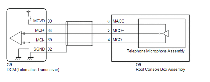 w/ Sliding Roof

CAUTION / NOTICE / HINT
HINT:
Before performing this diagnostic procedure, make sure to perform Health Check and confirm that the DCM/VIN registration information is correct.
Click here

PROCEDURE
| 1. |
CONFIRM MODEL |
(a) Choose the model to be inspected.
| Result |
Proceed to |
|---|---|
| w/ Sliding Roof |
A |
| w/o Sliding Roof |
B |
| B |
 | GO TO STEP 8 |
|
| 2. |
CHECK DTC |
(a) Turn the engine switch off.
(b) Connect the Techstream to the DLC3.
(c) Turn the engine switch on (IG) and wait for 10 seconds.
(d) Turn the Techstream on.
(e) Clear the DTCs.
Body Electrical > Telematics > Clear DTCs(f) Recheck for DTCs.
Body Electrical > Telematics > Trouble Codes|
Result | Proceed to |
|---|---|
|
DTC B1572 is output | A |
|
DTC B1572 is not output |
B |
| B |
| CHECK FOR INTERMITTENT PROBLEMS |
|
| 3. |
INSPECT ROOF CONSOLE BOX SUB-ASSEMBLY (TELEPHONE MICROPHONE ASSEMBLY POWER SOURCE) |
| (a) Remove the roof console box sub-assembly but do not disconnect the connectors. Click here |
|
(b) Measure the voltage and resistance according to the value(s) in the table below.
Standard Voltage:
|
Tester Connection | Condition |
Specified Condition |
|---|---|---|
|
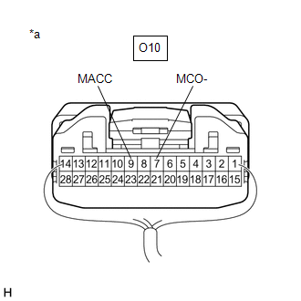
O10-9 (MACC) - Body ground |
Engine switch on (ACC) |
4 to 6 V |
Standard Resistance:
|
Tester Connection | Condition |
Specified Condition |
|---|---|---|
|
O10-7 (MCO-) - Body ground |
Always | Below 1 Ω |
| NG | | GO TO STEP 6 |
|
| 4. |
CHECK HARNESS AND CONNECTOR (DCM (TELEMATICS TRANSCEIVER) - ROOF CONSOLE BOX ASSEMBLY) |
(a) Disconnect the G9 DCM (Telematics Transceiver) connector.
(b) Disconnect the O10 roof console box sub-assembly connector.
(c) Measure the resistance according to the value(s) in the table below.
Standard Resistance:
|
Tester Connection | Condition |
Specified Condition |
|---|---|---|
|
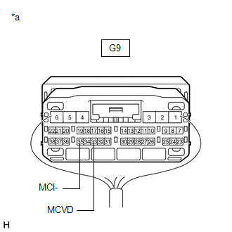
G9-34 (MCI+) - O10-8 (MCO+) |
Always | Below 1 Ω |
|
G9-34 (MCI+) or O10-8 (MCO+) - Body ground |
Always | 10 kΩ or higher |
|
G9-35 (MCI-) - O10-7 (MCO-) |
Always | Below 1 Ω |
|
G9-35 (MCI-) or O10-7 (MCO-) - Body ground |
Always | 10 kΩ or higher |
|
G9-32 (SGND) - Body ground |
Always | 10 kΩ or higher |
| NG | | REPAIR OR REPLACE HARNESS OR CONNECTOR |
|
| 5. |
REPLACE TELEPHONE MICROPHONE ASSEMBLY |
(a) Replace the telephone microphone assembly with a normal one and check if the same problem occurs again.
Click here
OK:
The system returns to normal.
| OK | | END |
| NG | | REPLACE ROOF CONSOLE BOX SUB-ASSEMBLY |
| 6. |
INSPECT DCM (TELEMATICS TRANSCEIVER) (TELEPHONE MICROPHONE ASSEMBLY POWER SOURCE) |
| (a) Remove the DCM (Telematics Transceiver) but do not disconnect the connectors. Click here |
|
(b) Measure the voltage and resistance according to the value(s) in the table below.
Standard Voltage:
|
Tester Connection | Condition |
Specified Condition |
|---|---|---|
|
G9-33 (MCVD) - Body ground |
Engine switch on (ACC) |
4 to 6 V |
Standard Resistance:
|
Tester Connection | Condition |
Specified Condition |
|---|---|---|
|
G9-35 (MCI-) - Body ground |
Always | Below 1 Ω |
| OK | | REPAIR OR REPLACE HARNESS OR CONNECTOR |
|
| 7. |
REPLACE DCM (TELEMATICS TRANSCEIVER) |
(a) Replace the DCM (Telematics Transceiver).
Click here
NOTICE:
| NEXT | | PERFORM DCM ACTIVATION |
| 8. |
CHECK DTC |
(a) Turn the engine switch off.
(b) Connect the Techstream to the DLC3.
(c) Turn the engine switch on (IG) and wait for 10 seconds.
(d) Turn the Techstream on.
(e) Clear the DTCs.
Body Electrical > Telematics > Clear DTCs(f) Recheck for DTCs.
Body Electrical > Telematics > Trouble Codes|
Result | Proceed to |
|---|---|
|
DTC B1572 is output | A |
|
DTC B1572 is not output |
B |
| B |
| CHECK FOR INTERMITTENT PROBLEMS |
|
| 9. |
INSPECT ROOF CONSOLE BOX SUB-ASSEMBLY (TELEPHONE MICROPHONE ASSEMBLY POWER SOURCE) |
| (a) Remove the roof console box sub-assembly but do not disconnect the connectors. Click here |
|
(b) Measure the voltage and resistance according to the value(s) in the table below.
Standard Voltage:
|
Tester Connection | Condition |
Specified Condition |
|---|---|---|
|
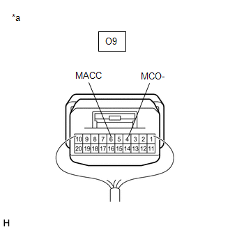
O9-6 (MACC) - Body ground |
Engine switch on (ACC) |
4 to 6 V |
Standard Resistance:
|
Tester Connection | Condition |
Specified Condition |
|---|---|---|
|
O9-4 (MCO-) - Body ground |
Always | Below 1 Ω |
| NG | | GO TO STEP 12 |
|
| 10. |
CHECK HARNESS AND CONNECTOR (DCM (TELEMATICS TRANSCEIVER) - ROOF CONSOLE BOX ASSEMBLY) |
(a) Disconnect the G9 DCM (Telematics Transceiver) connector.
(b) Disconnect the O9 roof console box sub-assembly connector.
(c) Measure the resistance according to the value(s) in the table below.
Standard Resistance:
|
Tester Connection | Condition |
Specified Condition |
|---|---|---|
|
G9-34 (MCI+) - O9-5 (MCO+) |
Always | Below 1 Ω |
|
G9-34 (MCI+) or O9-5 (MCO+) - Body ground |
Always | 10 kΩ or higher |
|
G9-35 (MCI-) - O9-4 (MCO-) |
Always | Below 1 Ω |
|
G9-35 (MCI-) or O9-4 (MCO-) - Body ground |
Always | 10 kΩ or higher |
|
G9-32 (SGND) - Body ground |
Always | 10 kΩ or higher |
| NG | | REPAIR OR REPLACE HARNESS OR CONNECTOR |
|
| 11. |
REPLACE TELEPHONE MICROPHONE ASSEMBLY |
(a) Replace the telephone microphone assembly with a normal one and check if the same problem occurs again.
Click here
OK:
The system returns to normal.
| OK | | END |
| NG | | REPLACE ROOF CONSOLE BOX SUB-ASSEMBLY |
| 12. |
INSPECT DCM (TELEMATICS TRANSCEIVER) (TELEPHONE MICROPHONE ASSEMBLY POWER SOURCE) |
| (a) Remove the DCM (Telematics Transceiver) but do not disconnect the connectors. Click here |
|
(b) Measure the voltage and resistance according to the value(s) in the table below.
Standard Voltage:
|
Tester Connection | Condition |
Specified Condition |
|---|---|---|
|
G9-33 (MCVD) - Body ground |
Engine switch on (ACC) |
4 to 6 V |
Standard Resistance:
|
Tester Connection | Condition |
Specified Condition |
|---|---|---|
|
G9-35 (MCI-) - Body ground |
Always | Below 1 Ω |
| OK | | REPAIR OR REPLACE HARNESS OR CONNECTOR |
|
| 13. |
REPLACE DCM (TELEMATICS TRANSCEIVER) |
(a) Replace the DCM (Telematics Transceiver).
Click here
NOTICE:
| NEXT | | PERFORM DCM ACTIVATION |
DESCRIPTION
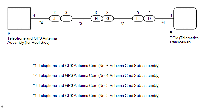
These DTCs are stored when the DCM (Telematics Transceiver) detects an open or a short in the telephone and GPS antenna assembly (for Roof Side) circuit. The DCM (Telematics Transceiver) oscillates and receives 824 - 894 MHz or 1850 - 1990 MHz radio-frequency through the telephone and GPS antenna assembly (for Roof Side).
|
DTC No. | Detection Item |
DTC Detection Condition | Trouble Area |
|---|---|---|---|
|
B1573 | Short in Telephone Antenna Circuit |
Telephone and GPS antenna assembly (for Roof Side) impedance is lower than malfunction criterion for 10 seconds when engine switch is on (IG). (Short circuit) |
|
| B15CB |
Telematics Transceiver Antenna Disconnected |
Telephone and GPS antenna assembly (for Roof Side) impedance is higher than malfunction criterion for 10 seconds when engine switch is on (IG). (Open circuit) |
|
WIRING DIAGRAM
CAUTION / NOTICE / HINT
HINT:
Click here 
Click here
PROCEDURE
|
1. | CHECK DTC |
(a) Turn the engine switch off.
(b) Connect the Techstream to the DLC3.
(c) Turn the engine switch on (IG) and wait for 10 seconds.
(d) Turn the Techstream on.
(e) Clear the DTCs.
Body Electrical > Telematics > Clear DTCs(f) Recheck for DTCs.
Body Electrical > Telematics > Trouble Codes|
Result | Proceed to |
|---|---|
|
DTC B1573 or B15CB is output |
A |
| DTC B1573 or B15CB is not output |
B |
| B |
 | CHECK FOR INTERMITTENT PROBLEMS |
|
| 2. |
INSPECT TELEPHONE AND GPS ANTENNA ASSEMBLY (for Roof Side) |
| (a) Disconnect the telephone and GPS antenna assembly (for Roof Side) connector. |
|
(b) Measure the resistance according to the value(s) in the table below.
Standard Resistance:
|
Tester Connection | Condition |
Specified Condition |
|---|---|---|
|
4 - 4a | Always |
4 to 11 kΩ |
| NG | | REPLACE TELEPHONE AND GPS ANTENNA ASSEMBLY (for Roof Side) |
|
| 3. |
INSPECT TELEPHONE AND GPS ANTENNA CORD (NO. 2 ANTENNA CORD SUB-ASSEMBLY) |
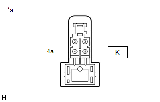
| (a) Disconnect the K telephone and GPS antenna cord (No. 2 antenna cord sub-assembly) connector. |
|
| (b) Disconnect the J telephone and GPS antenna cord (No. 2 antenna cord sub-assembly) connector. |
|
(c) Measure the resistance according to the value(s) in the table below.
Standard Resistance:
|
Tester Connection | Condition |
Specified Condition |
|---|---|---|
|
K-4 - J-1 | Always |
Below 1 Ω |
|
K-4 or J-1 - Body ground |
Always | 10 kΩ or higher |
|
K-4a - J-1a | Always |
Below 1 Ω |
|
K-4a or J-1a - Body ground |
Always | 10 kΩ or higher |
| NG | | REPLACE TELEPHONE AND GPS ANTENNA CORD (NO. 2 ANTENNA CORD SUB-ASSEMBLY) |
|
| 4. |
INSPECT TELEPHONE AND GPS ANTENNA CORD (NO. 3 ANTENNA CORD SUB-ASSEMBLY) |
| (a) Disconnect the I telephone and GPS antenna cord (No. 3 antenna cord sub-assembly) connector. |
|
| (b) Disconnect the H telephone and GPS antenna cord (No. 3 antenna cord sub-assembly) connector. |
|
(c) Measure the resistance according to the value(s) in the table below.
Standard Resistance:
|
Tester Connection | Condition |
Specified Condition |
|---|---|---|
|
I-3 - H-3 | Always |
Below 1 Ω |
|
I-3 or H-3 - Body ground |
Always | 10 kΩ or higher |
|
I-3a - H-3a | Always |
Below 1 Ω |
|
I-3a or H-3a - Body ground |
Always | 10 kΩ or higher |
| NG | | REPLACE TELEPHONE AND GPS ANTENNA CORD (NO. 3 ANTENNA CORD SUB-ASSEMBLY) |
|
| 5. |
INSPECT TELEPHONE AND GPS ANTENNA CORD (NO. 4 ANTENNA CORD SUB-ASSEMBLY) |
| (a) Disconnect the G telephone and GPS antenna cord (No. 4 antenna cord sub-assembly) connector. |
|
| (b) Disconnect the E telephone and GPS antenna cord (No. 4 antenna cord sub-assembly) connector. |
|
(c) Measure the resistance according to the value(s) in the table below.
Standard Resistance:
|
Tester Connection | Condition |
Specified Condition |
|---|---|---|
|
G-3 - E-3 | Always |
Below 1 Ω |
|
G-3 or E-3 - Body ground |
Always | 10 kΩ or higher |
|
G-3a - E-3a | Always |
Below 1 Ω |
|
G-3a or E-3a - Body ground |
Always | 10 kΩ or higher |
| NG | | REPLACE TELEPHONE AND GPS ANTENNA CORD (NO. 4 ANTENNA CORD SUB-ASSEMBLY) |
|
| 6. |
INSPECT TELEPHONE AND GPS ANTENNA CORD (NO. 6 ANTENNA CORD SUB-ASSEMBLY) |
| (a) Disconnect the D telephone and GPS antenna cord (No. 6 antenna cord sub-assembly) connector. |
|
| (b) Disconnect the B telephone and GPS antenna cord (No. 6 antenna cord sub-assembly) connector. |
|
(c) Measure the resistance according to the value(s) in the table below.
Standard Resistance:
|
Tester Connection | Condition |
Specified Condition |
|---|---|---|
|
D-3 - B-1 | Always |
Below 1 Ω |
|
D-3 or B-1 - Body ground |
Always | 10 kΩ or higher |
|
D-3a - B-1a | Always |
Below 1 Ω |
|
D-3a or B-1a - Body ground |
Always | 10 kΩ or higher |
| NG | | REPLACE TELEPHONE AND GPS ANTENNA CORD (NO. 6 ANTENNA CORD SUB-ASSEMBLY) |
|
| 7. |
REPLACE TELEPHONE AND GPS ANTENNA ASSEMBLY (for Roof Side) |
(a) Replace the telephone and GPS antenna assembly (for Roof Side) with a known good one and check if the same problem occurs again.
Click here
OK:
The system returns to normal.
| OK | | END |
|
| 8. |
REPLACE DCM (TELEMATICS TRANSCEIVER) |
(a) Replace the DCM (Telematics Transceiver).
Click here
NOTICE:
| NEXT | | PERFORM DCM ACTIVATION |
DATA LIST / ACTIVE TEST
DATA LIST
HINT:
Using the Techstream to read the Data List allows the values or states of switches, sensors, actuators and other items to be read without removing any parts. This non-intrusive inspection can be very useful because intermittent conditions or signals may be discovered before parts or wiring is disturbed. Reading the Data List information early in troubleshooting is one way to save diagnostic time.
NOTICE:
In the table below, the values listed under "Normal Condition" are reference values. Do not depend solely on these reference values when deciding whether a part is faulty or not.
(a) Connect the Techstream to the DLC3.
(b) Turn the engine switch on (IG).
(c) Turn the Techstream on.
(d) Enter the following menus: Body Electrical / Telematics / Data List.
(e) According to the display on the Techstream, read the "Data List".
Body Electrical > Telematics > Data List|
Tester Display | Measurement Item |
Range | Normal Condition |
Diagnostic Note |
|---|---|---|---|---|
|
MEID | Only MEID (cellular module ID) is displayed on the Techstream. Serial number to be assigned to cellular module in telematics. |
Display the cellular module ID number |
Display the cellular module ID number |
- |
| Number of Trouble Codes |
The number of the DTC which is currently output |
Min.: 0 or Max.: 255 | Number of DTCs will be displayed |
- |
DCM ACTIVATION
DCM ACTIVATION
This function should be used to activate the DCM (Telematics Transceiver) after a new DCM (Telematics Transceiver) has been installed. During the DCM Activation process, the Techstream automatically provides the telematics service provider with the new DCM (Telematics Transceiver) information and deletes the old DCM (Telematics Transceiver) information associated with the vehicle. The DCM (Telematics Transceiver) that was replaced should be returned to the parts department.
(a) Connect the Techstream to the DLC3.
(b) Turn the engine switch on (IG).
(c) Press SOS button 1 time to confirm Service part is currently defective ("Safety Connect is not initialized." voice prompt should be heard).
(d) Turn the Techstream on.
(e) Choose "Telematics" from the System Selection Menu, and then click "Utility".
(f) Click "DCM Service" on the Utility Selection Menu.
Body Electrical > Telematics > Utility|
Tester Display |
|---|
| DCM Service |
(g) Choose "Activate DCM" and then click "Next" on the DCM Service Utility.
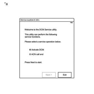
|
*a | Example |
(h) Follow the instructions on the Techstream.
HINT:
|
Fault Code | Reason |
|---|---|
|
20 | System timeout. |
|
61 | DCM (Telematics Transceiver) has been identified as a previously used part. |
|
62 | VIN not recognized by telematics provider. |
|
63 | DCM (Telematics Transceiver) already associated with a vehicle. Use another authorized service part. |
|
64 | DCM (Telematics Transceiver) not recognized. |
|
66 | DCM (Telematics Transceiver) is not a service part. Use only an authorized service part. |
|
67 | Unable to activate at this time. |
HINT:
If the one these fault code is present, follow the procedure indicated in the following list.
*: As the fault could also be caused by a problem in communicating with the call center, before replacing the DCM (Telematics Transceiver), check with the call center to determine it there is a database or communication problem.
(i) Push the manual (SOS) switch to call an operator and confirm that the DCM (Telematics Transceiver) is activated.
DCM OPERATION HISTORY
DCM OPERATION HISTORY
This function shows the telematics network status when the DCM (Telematics Transceiver) was operated. Use this when no DTC is present but this telematics system was unable to connect to the call center. This symptom may occur if cell phone signal strength is very weak.
(a) Connect the Techstream to the DLC3.
(b) Turn the engine switch on (IG).
(c) Turn the Techstream on.
(d) Choose "Telematics" from the System Selection Menu, and then click "Utility".
(e) Click "DCM Operation History" on the Utility Selection Menu.
Body Electrical > Telematics > Utility|
Tester Display |
|---|
| DCM Operation History |
(f) Follow the instructions on the Techstream.
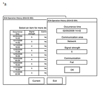
|
*a | Example |
HINT:
|
Result |
Description |
|---|---|
|
Success |
A successfully call made using the manual (SOS) switch or the navigation system (Destination Assist-If available) |
|
Fail*1 |
A call that was unsuccessful. |
NOTICE:
*1: A failure can also be caused by manually ending an SOS call, and does not necessarily indicate a device malfunction.
HINT:
*2: When communication to the call center fails, "Fail" is displayed.
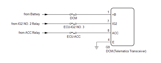
DESCRIPTION
This is the power source circuit to operate the DCM (Telematics Transceiver).
WIRING DIAGRAM
CAUTION / NOTICE / HINT
NOTICE:
Inspect the fuses for circuits related to this system before performing the following procedure.
PROCEDURE
| 1. |
CHECK HARNESS AND CONNECTOR (DCM (TELEMATICS TRANSCEIVER) - BATTERY AND GROUND) |
| (a) Disconnect the G9 DCM (Telematics Transceiver) connector. |
|
(b) Measure the resistance according to the value(s) in the table below.
Standard Resistance:
|
Tester Connection | Condition |
Specified Condition |
|---|---|---|
|
G9-4 (E) - Body ground |
Always | Below 1 Ω |
(c) Measure the voltage according to the value(s) in the table below.
Standard Voltage:
|
Tester Connection | Condition |
Specified Condition |
|---|---|---|
|
G9-1 (+B) - G9-4 (E) |
Always | 11 to 14 V |
|
G9-7 (IG2) - G9-4 (E) |
Engine switch on (IG) |
11 to 14 V |
|
G9-8 (ACC) - G9-4 (E) |
Engine switch on (ACC) |
11 to 14 V |
| OK |  | PROCEED TO NEXT SUSPECTED AREA SHOWN IN PROBLEM SYMPTOMS TABLE |
| NG | | REPAIR OR REPLACE HARNESS OR CONNECTOR |
DIAGNOSIS SYSTEM
DESCRIPTION
(a) The DCM (Telematics Transceiver) control the vehicle safety connect system functions. Safety connect system data and Diagnostic Trouble Codes (DTCs) can be read through the vehicle Data Link Connector 3 (DLC3). In some cases, a malfunction may be occurring in the safety connect system. When the system seems to be malfunctioning, use the Techstream to check for malfunctions and perform repairs.
CHECK DLC3
(a) Check the DLC3.
Click here 
INSPECT BATTERY VOLTAGE
(a) Measure the battery voltage.
Standard Voltage:
11 to 14 V
If the voltage is below 11 V, recharge or replace the battery.
CHECK INDICATOR
(a) When a malfunction is detected in the safety connect system, the manual (SOS) switch red indicator on the manual (SOS) switch illuminates to inform the driver of the malfunction.
Click here
DIAGNOSTIC TROUBLE CODE CHART
Safety Connect System|
DTC No. | Detection Item |
Link |
|---|---|---|
| B1536 |
Short in Telephone SUB Antenna Circuit |
|
|
B1537 | Open in Telephone SUB Antenna Circuit |
|
|
B1570 | Manual (SOS) Switch Red Indicator Malfunction |
|
|
B1571 | Manual (SOS) Switch Green Indicator Malfunction |
|
|
B1572 | Telephone Microphone Error |
|
|
B1573 | Short in Telephone Antenna Circuit |
|
|
B15A8 | Telematics Transceiver Malfunction |
|
|
B15C0 | Short in GPS Antenna |
|
|
B15C1 | Open in GPS Antenna |
|
|
B15C4 | Airbag Signal Malfunction/Not Input |
|
|
B15C5 | Manual Button Malfunction |
|
|
B15CB | Telematics Transceiver Antenna Disconnected |
|
|
B15CC | Backup Battery Failure |
|
|
B15EC | Backup Battery Degradation |
|
DTC CHECK / CLEAR
CHECK DTC
(a) Connect the Techstream to the DLC3.
(b) Turn the engine switch on (IG).
(c) Turn the Techstream on.
(d) Enter the following menus: Body Electrical / Telematics / Trouble Codes.
Body Electrical > Telematics > Trouble Codes(e) Check the details of the DTC(s).
Click here

CLEAR DTC
(a) Connect the Techstream to the DLC3.
(b) Turn the engine switch on (IG).
(c) Turn the Techstream on.
(d) Enter the following menus: Body Electrical / Telematics / Trouble Codes.
Body Electrical > Telematics > Clear DTCs(e) Clear the DTCs.
DESCRIPTION
After the engine switch is turned on (IG), the DCM (Telematics Transceiver) will enter into a self check mode. The manual (SOS) switch red indicator will illuminate for 2 seconds and turn off followed by the manual (SOS) switch green indicator illuminating and remaining on under normal operation.
If both indicators illuminate and begin to blink simultaneously, this indicates that the DCM (Telematics Transceiver) is in "Shipping Mode." If no DTCs are present, both the green and red indicators will turn off after blinking. The activation sequence must be performed.
CAUTION / NOTICE / HINT
HINT:
In shipping mode, the system will attempt to activate to shell mode automatically each time engine switch on (IG).
PROCEDURE
| 1. |
CHANGE SUBSCRIPTION MODE |
(a) Turn the engine switch on (IG).
(b) Push the manual (SOS) switch.
(c) The vehicle will issue a voice prompt: "To activate, please press the button again within 5 seconds."
(d) Push the manual (SOS) switch and a beep will be emitted.
(e) The telematics service provider will send an End Call command and the manual (SOS) switch green indicator will illuminate.
(f) A voice prompt will state: "Activation Complete." (This may take up to 3 minutes.)
(g) Turn the engine switch off.
|
| 2. |
CHECK SUBSCRIPTION MODE |
(a) Turn the engine switch on (IG).
(b) Confirm that the manual (SOS) switch red indicator illuminates for 2 seconds and turns off and the manual (SOS) switch green indicator illuminates and remains on.
Click here 
| NEXT |  | END |
DESCRIPTION
If the red and green indicators fail to illuminate after the engine switch is turned on (IG), the vehicle does not recognize the DCM (Telematics Transceiver). The DCM (Telematics Transceiver) connectors may have been disconnected or the DCM (Telematics Transceiver) is malfunctioning.
PROCEDURE
| 1. |
HEALTH CHECK |
(a) Turn the engine switch off.
(b) Connect the Techstream to the DLC3.
(c) Turn the engine switch on (IG) and wait for 10 seconds.
(d) Turn the Techstream on.
(e) Perform "Health Check" using the Techstream and check that Telematics (Safety Connect) is listed on "Health Check Result".
Click here 
|
Result | Proceed to |
|---|---|
|
"Telematics" is displayed on the Techstream |
A |
| "Telematics" is not displayed on the Techstream |
B |
| B |
 | PROCEED TO NEXT SUSPECTED AREA SHOWN IN PROBLEM SYMPTOMS TABLE |
|
| 2. |
CHECK DTC |
(a) Turn the engine switch off.
(b) Connect the Techstream to the DLC3.
(c) Turn the engine switch on (IG) and wait for 10 seconds.
(d) Turn the Techstream on.
(e) Check current DTCs and history DTCs.
Click here
|
Result | Proceed to |
|---|---|
|
DTCs are not output | A |
|
DTCs are output | B |
| A |
| CHECK FOR INTERMITTENT PROBLEMS |
| B |
| GO TO DIAGNOSTIC TROUBLE CODE CHART |
DESCRIPTION
After turning the engine switch on (IG), the DCM (Telematics Transceiver) will enter into self check mode. The manual (SOS) switch red indicator will illuminate for 2 seconds and turn off followed by the manual (SOS) switch green indicator illuminating and remaining on under normal operation. If neither the red nor green indicators remain on, verification of the subscription should be performed.
PROCEDURE
| 1. |
CONFIRM GREEN INDICATOR COMES ON |
(a) After the engine switch is turned on (IG) and the manual (SOS) switch red indicator has come on for 2 seconds, confirm that the manual (SOS) switch green indicator comes on for 2 seconds.
OK:
Green indicator comes on.
| NG |  | GO TO STEP 6 |
|
| 2. |
CONFIRM SUBSCRIPTION MODE |
(a) Confirm the indicator status 5 seconds after the engine switch is turned on (IG).
|
Result | Proceed to |
|---|---|
|
Green indicator remains on |
A |
| Green indicator remains off |
B |
HINT:
If red and green indicators are flashing, the system is in shipping mode, so the system should be changed to either active mode or deactive mode.
| A |
| CHECK FOR INTERMITTENT PROBLEMS |
|
| 3. |
INPUT VIN WITH TECHSTREAM |
(a) Turn the engine switch off.
(b) Connect the Techstream to the DLC3.
(c) Turn the engine switch on (IG) and wait for 10 seconds.
(d) Turn the Techstream on.
(e) Select "Vehicle Inquiry" and input the VIN.
|
| 4. |
CONFIRM SUBSCRIPTION MODE |
(a) Confirm the indicator status at 5 seconds after the engine switch is turned on (IG).
|
Result | Proceed to |
|---|---|
|
Green indicator remains on |
A |
| Green indicator remains off |
B |
| A |
| END |
|
| 5. |
REPLACE DCM (TELEMATICS TRANSCEIVER) |
(a) Replace the DCM (Telematics Transceiver).
Click here 
NOTICE:
| NEXT | | PERFORM DCM ACTIVATION |
| 6. |
CHECK DTC |
(a) Turn the engine switch off.
(b) Connect the Techstream to the DLC3.
(c) Turn the engine switch on (IG) and wait for 10 seconds.
(d) Turn the Techstream on.
(e) Perform "Health Check" and check for current DTCs.
Click here
|
Result | Proceed to |
|---|---|
|
DTCs are not output | A |
|
DTCs are output | B |
| B |
| GO TO DIAGNOSTIC TROUBLE CODE CHART |
|
| 7. |
REPLACE DCM (TELEMATICS TRANSCEIVER) |
(a) Replace the DCM (Telematics Transceiver).
Click here
NOTICE:
| NEXT | | PERFORM DCM ACTIVATION |
HEALTH CHECK
HEALTH CHECK
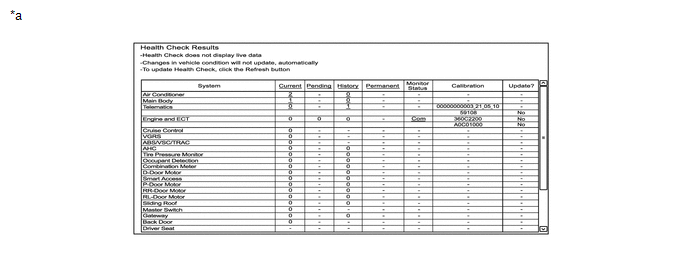
Health Check provides an overall view of vehicle status including telematics. Health Check will provide DCM (Telematics Transceiver) software version, PRL version, and applicable DTCs and fault codes related to telematics.
(a) Connect the Techstream to the DLC3.
(b) Turn the engine switch on (IG).
(c) Turn the Techstream on.
(d) Click "Health Check".
|
Fault Code | Reason |
|---|---|
|
62 | VIN not recognized by telematics provider. |
|
64 | DCM (Telematics Transceiver) not recognized. |
|
65 | VIN mismatch with DCM (Telematics Transceiver). |
HINT:
*: Verify VIN is correct in ECM. Run Vehicle Inquiry on Techstream and verify VIN is correct.
(e) Data is displayed under "Telematics".
|
*a | Example |
- | - |
CAUTION / NOTICE / HINT
HINT:
PROCEDURE
|
1. | VEHICLE BROUGHT TO WORKSHOP |
|
| 2. |
CUSTOMER PROBLEM ANALYSIS CHECK AND SYMPTOM CHECK |
HINT:
|
What |
Vehicle model, system name |
|
When |
Date, time, occurrence frequency |
|
Where |
Road conditions |
|
Under what conditions? |
Driving conditions, weather conditions |
|
How did it happen? |
Problem symptoms |
|
| 3. |
PRE-CHECK |
(a) Measure the battery voltage.
Standard Voltage:
11 to 14 V
If the voltage is below 11 V, recharge or replace the battery before proceeding to the next step.
(b) Check the fuses and relays.
(c) Check the connector connections and terminals to make sure that there are no abnormalities such as loose connections, deformation, etc.
|
| 4. |
VERIFY CUSTOMER SUBSCRIPTION IS ACTIVE* |
(a) Enter the VIN into Vehicle Inquiry on the Techstream and verify the subscription type and expiration date.
|
| 5. |
PERFORM HEALTH CHECK* |
(a) Perform "Health Check" and check for current DTCs.
Click here 
|
Result | Proceed to |
|---|---|
|
DTCs are not output | A |
|
DTCs are output | B |
| B |
 | GO TO DIAGNOSTIC TROUBLE CODE CHART |
|
| 6. |
PROBLEM SYMPTOMS TABLE |
(a) Refer to Problem Symptoms Table.
Click here
|
Result | Proceed to |
|---|---|
|
Fault is not listed in Problem Symptoms Table |
A |
| Fault is listed in Problem Symptoms Table |
B |
HINT:
If the symptom does not reoccur and no DTC is output, attempt to reproduce the symptoms.
Click here
| B |
| GO TO STEP 8 |
|
| 7. |
OVERALL ANALYSIS AND TROUBLESHOOTING* |
(a) Terminals of ECU
Click here
(b) Data List / Active Test
Click here
|
| 8. |
REPAIR OR REPLACE |
(a) Check if the DCM (Telematics Transceiver) has been replaced.
|
Result | Proceed to |
|---|---|
|
The DCM (Telematics Transceiver) has been replaced |
A |
| The DCM (Telematics Transceiver) has not been replaced |
B |
| B |
| GO TO STEP 10 |
|
| 9. |
PERFORM DCM ACTIVATION |
(a) Perform "DCM ACTIVATION".
Click here
|
| 10. |
CONFIRMATION TEST |
| NEXT | | END |
INITIALIZATION
RESET BUB (BACK-UP BATTERY) CONDITION
HINT:
If the BUB (Back-Up Battery) has been replaced, it is necessary to perform this procedure.
(a) Connect the Techstream to the DLC3.
(b) Turn the engine switch on (IG).
(c) Turn the Techstream on.
(d) Enter the following menus: Body Electrical / Telematics / Utility / Backup Battery Replacement Reset
Body Electrical > Telematics > Utility|
Tester Display |
|---|
| Backup Battery Replacement Reset |
(e) According to the display on the Techstream, perform Backup Battery Replacement Reset to reset the BUB (Back-Up Battery) replacement flag.
PARTS LOCATION
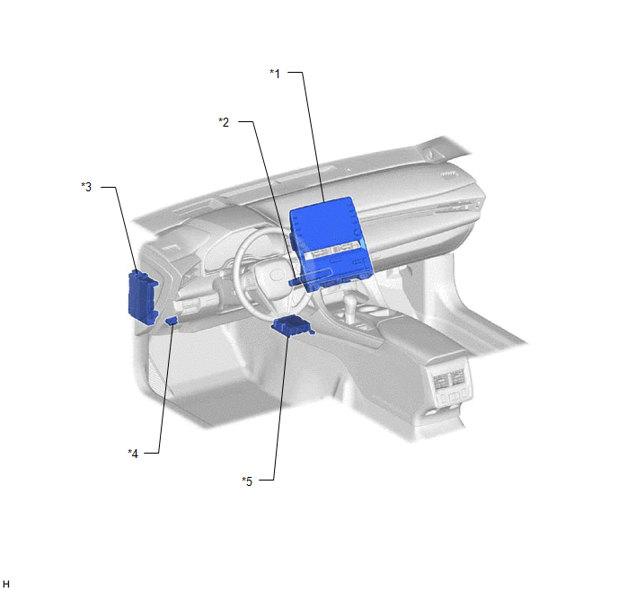
ILLUSTRATION
|
*1 | RADIO AND DISPLAY RECEIVER ASSEMBLY |
*2 | DCM (TELEMATICS TRANSCEIVER) - BUB (BACK-UP BATTERY) |
|
*3 | INSTRUMENT PANEL JUNCTION BLOCK ASSEMBLY - ECU-IG2 NO. 3 FUSE - ECU-ACC FUSE - DCM FUSE |
*4 | DLC3 |
|
*5 | AIRBAG ECU ASSEMBLY |
- | - |
ILLUSTRATION
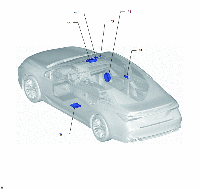
|
*1 | FRONT NO. 1 SPEAKER ASSEMBLY RH |
*2 | FRONT NO. 2 SPEAKER ASSEMBLY RH (for 8 Speakers) |
|
*3 | FRONT NO. 3 SPEAKER ASSEMBLY RH (for 14 Speakers) |
*4 | ROOF CONSOLE BOX SUB-ASSEMBLY - TELEPHONE MICROPHONE ASSEMBLY - MANUAL (SOS) SWITCH |
|
*5 | TELEPHONE AND GPS ANTENNA ASSEMBLY (for Roof Side) |
*6 | STEREO COMPONENT AMPLIFIER ASSEMBLY (for 14 Speakers) |
ILLUSTRATION
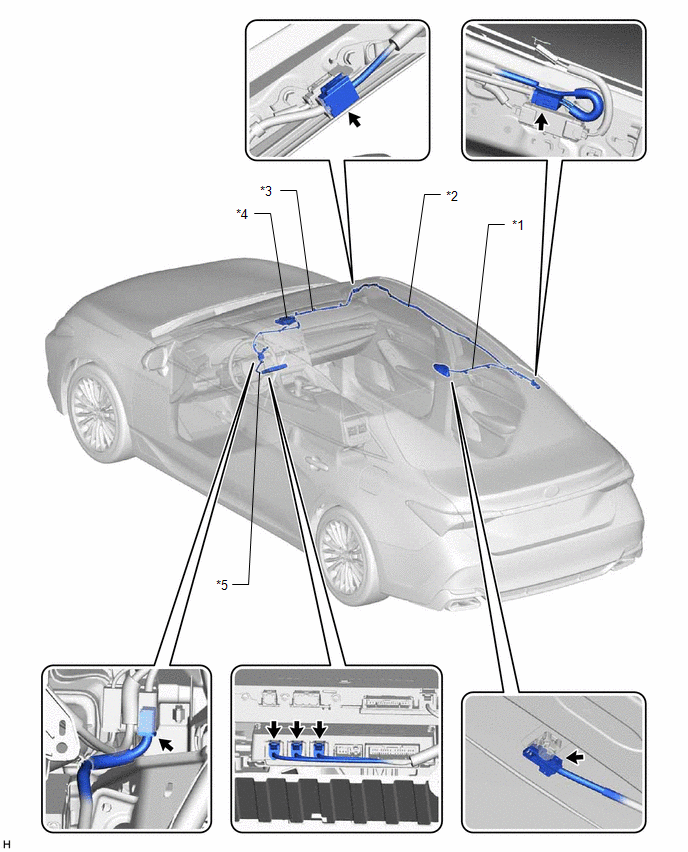
|
*1 | TELEPHONE AND GPS ANTENNA CORD (NO. 2 ANTENNA CORD SUB-ASSEMBLY) |
*2 | TELEPHONE AND GPS ANTENNA CORD (NO. 3 ANTENNA CORD SUB-ASSEMBLY) |
|
*3 | TELEPHONE AND GPS ANTENNA CORD (NO. 4 ANTENNA CORD SUB-ASSEMBLY) |
*4 | TELEPHONE AND GPS ANTENNA ASSEMBLY (for Front Side) |
|
*5 | TELEPHONE AND GPS ANTENNA CORD (NO. 6 ANTENNA CORD SUB-ASSEMBLY) |
- | - |
PRECAUTION
PRECAUTION FOR DISCONNECTING CABLE FROM NEGATIVE BATTERY TERMINAL
NOTICE:
When disconnecting the cable from the negative (-) battery terminal, initialize the following systems after the cable is reconnected.
|
System Name | See Procedure |
|---|---|
|
Lane Departure Alert System (w/ Steering Control) |
|
|
Intelligent Clearance Sonar System | |
|
Parking Assist Monitor System | |
|
Panoramic View Monitor System | |
|
Pre-collision System | |
|
Lighting System (for Gasoline Model with Cornering Light) |
WHEN DISCONNECTING BATTERY CABLE
(a) After turning the engine switch off, waiting time may be required before disconnecting the cable from the negative (-) battery terminal. Therefore, make sure to read the disconnecting the cable from the negative (-) battery terminal notices before proceeding with work.
Click here

WHEN AUTOMATIC COLLISION NOTIFICATION HAS ACTIVATED
(a) Perform "ACN CALL END" with Techstream to terminate ACN (Automatic Collision Notification) with the call center.
Click here
(b) The BUB (Back-Up Battery) must be replaced.
WHEN DISCONNECTING CONNECTORS FROM DCM (TELEMATICS TRANSCEIVER)
(a) The engine switch must be off.
WHEN REPLACING THE DCM (TELEMATICS TRANSCEIVER)
(a) After installing a new Telematics Data Communication Module (DCM (Telematics Transceiver)), perform "DCM ACTIVATION" with the Techstream. This allows the Telematics service provider to register the new DCM (Telematics Transceiver) and to delete the old DCM (Telematics Transceiver) information from their database.
Click here
NOTICE:
Do not replace the DCM (Telematics Transceiver) with one from another vehicle.
WHEN UNABLE TO CONTACT WITH CALL CENTER BUT NO DTC
(a) This may occur when the cellular signal strength was very weak. Check "DCM OPERATION HISTORY" with the Techstream.
Click here
WHEN DIAGNOSING DCM (TELEMATICS TRANSCEIVER)
(a) While attempting to diagnose the DCM (Telematics Transceiver), do not use a DCM (Telematics Transceiver) from another vehicle. Each DCM (Telematics Transceiver) is registered to a specific VIN and should not be tested in another vehicle.
PROBLEM SYMPTOMS TABLE
HINT:
|
Symptom | Suspected Area |
Link |
|---|---|---|
|
"Communication Module failure detected, please contact your dealer" message is played |
Refer to HEALTH CHECK |
|
|
Diagnostic Trouble Code Chart (Red Indicator has failed and cannot indicate a failure) |
| |
|
"Communication Module Activation Failed" message is played |
Contact Telematics Service Provider to verify any network problems |
- |
| Wait for a while, then move to different location and retry (try to find location with better signal reception) |
- | |
| Refer to HEALTH CHECK |
| |
|
Diagnostic Trouble Code Chart |
| |
|
"Unable to Connect the Emergency Call Center" or "Unable to Connect to the Call Center" message is played |
Wait for a while, then move to different location and retry (try to find location with better signal reception) |
- |
| Perform Vehicle Inquiry on Techstream and verify subscription status |
- | |
| Refer to UNABLE TO CONNECT TO CALL CENTER |
| |
|
"Safety Connect is not active" message is played |
Perform Vehicle Inquiry on Techstream and verify subscription status |
- |
| Explain to the customer that the system is in deactive mode, and confirm whether or not they would like to change to active mode |
- |
|
Symptom | Suspected Area |
Link |
|---|---|---|
|
Green indicator abnormal (Remains OFF) |
Refer to DCM POWER SOURCE CIRCUIT |
|
|
Refer to GREEN INDICATOR REMAINS OFF |
| |
|
Red indicator abnormal (Remains ON) |
Refer to RED INDICATOR REMAINS ON |
|
|
Green and red indicators abnormal (Remains OFF) |
Refer to GREEN AND RED INDICATORS DO NOT COME ON WHEN IG-ON |
|
|
Refer to DCM POWER SOURCE CIRCUIT |
| |
|
DCM (Telematics Transceiver) |
| |
|
Green and red indicators blink simultaneously |
Refer to GREEN AND RED INDICATORS BLINK SIMULTANEOUSLY |
|
DESCRIPTION
This means that the DCM (Telematics Transceiver) has detected a malfunction in the safety connect system and stored a DTC.
PROCEDURE
| 1. |
CHECK DTC |
(a) Turn the engine switch off.
(b) Connect the Techstream to the DLC3.
(c) Turn the engine switch on (IG) and wait for 10 seconds.
(d) Turn the Techstream on.
(e) Perform "Health Check" and check for current DTCs.
Click here 
|
Result | Proceed to |
|---|---|
|
DTCs are not output | A |
|
DTCs are output | B |
| B |
 | GO TO DIAGNOSTIC TROUBLE CODE CHART |
|
| 2. |
REPLACE DCM (TELEMATICS TRANSCEIVER) |
(a) Replace the DCM (Telematics Transceiver).
Click here
NOTICE:
| NEXT | | PERFORM DCM ACTIVATION |
SYSTEM DESCRIPTION
DESCRIPTION
(a) Safety Connect performs ACN (Automatic Collision Notification), manual emergency calling, stolen vehicle tracking and roadside assistance service by, audio and data communications between the vehicle and call center through a cellular phone network. As shown in the illustration, when a collision is detected, the vehicle sends its location calculated based on GPS signals and the identification code of the DCM (Telematics Transceiver) to a call center. After the necessary information has been gathered, the call center will relay this information to emergency services.
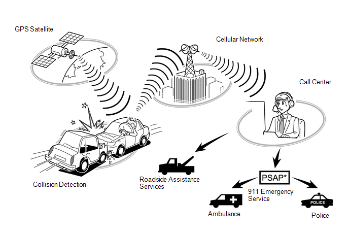
*: Public Safety Answering Point
SYSTEM FUNCTION
(a) ACN (Automatic Collision Notification)
(1) When a collision is detected, the vehicle connects to the call center automatically and reports the vehicle location and vehicle information by data communication. The operator will connect to the vehicle and communicate with the occupant. Even if the occupant does not answer, the operator can notify emergency services.
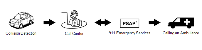
(b) Manual Emergency Call
(1) After pressing the manual (SOS) switch, the occupant can talk to an operator from the call center to seek assistance.
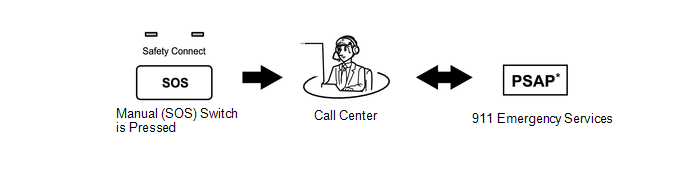
(c) Stolen Vehicle Locator
(1) After the vehicle has been reported stolen to the police, the customer can contact the call center to begin the stolen vehicle locator process. The operator locates this vehicle by GPS and provides information to the police.
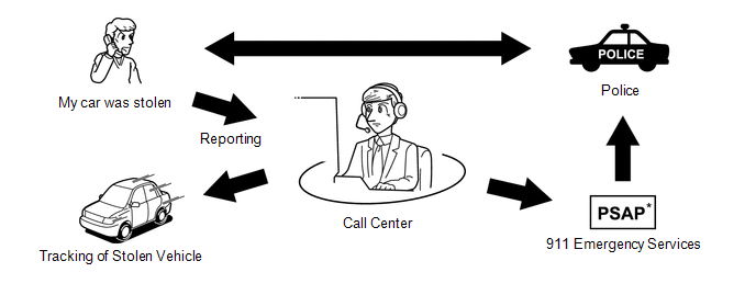
(d) Roadside Assistance Service
(1) Pressing the manual (SOS) switch will contract the call center, and a wide range of help, such as towing, flat tire, fuel delivery, etc., can be provided.
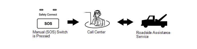
*: Public Safety Answering Point
HINT:
The shape of the manual (SOS) switch shown in the illustration is an example, and may differ from that of an actual vehicle.
VOICE GUIDANCE FUNCTION
HINT:
The system plays back the following voice prompts in the situations shown.
|
Voice Prompt | Usage Condition |
|---|---|
|
Communication Module failure detected, please contact your dealer. |
When system detects LED failure (Red only), and another DTC is set. Message is played once at each engine switch on (IG) until the problem is fixed. |
|
Connecting to the Call Center. | DCM Activation start. |
|
Communication Module Activation failed. |
DCM Activation fails for some reason. |
|
Communication Module Activation complete. |
DCM Activation completed successfully. |
|
If you continue to receive this message, contact your dealer. |
Follows Activation Sequence. |
|
Unable to Connect to the Call Center. |
- |
| Impact detected. |
When DCM (Telematics Transceiver) receives collision detection signal. |
|
Connecting to the Emergency Call Center. |
Call initiated to call center. |
|
Unable to Connect to the Emergency Call Center. |
DCM (Telematics Transceiver) cannot connect to Emergency Call Center for some reason. |
|
To cancel, please press the button again. |
To end the call manually. |
|
Emergency call canceled. | Confirmation that the call has been canceled. |
|
The system will try again. | Could not connect to call center. |
|
To activate, please press the button again within 5 seconds. |
This voice prompt is instruction for activation. |
|
Safety Connect is not active. | When DCM (Telematics Transceiver) is in Deactive mode. |
|
To sign up for service please call 1855-405-6500 and a representative will assist you. |
When DCM (Telematics Transceiver) is in Deactive mode. |
BUB (BACK-UP BATTERY) OUTLINE
(a) When ACN (Automatic Collision Notification) occurs, the BUB (Back-Up Battery) provides power to the DCM (Telematics Transceiver).
NOTICE:
HINT:
When a Manual Emergency Call is made, the BUB (Back-Up Battery) is not used as the power source.
(b) When it is time to replace the BUB (Back-Up Battery), the manual (SOS) switch red indicator will come on. The DCM (Telematics Transceiver) will also store a DTC.
INDICATOR CONTROL FUNCTION DURING DCM (TELEMATICS TRANSCEIVER) SELF CHECK MODE
HINT:
Every time after the engine switch is turned on (IG), the DCM (Telematics Transceiver) will enter into a self check mode. The manual (SOS) switch red indicator will illuminate for 2 seconds and then turn off and then the manual (SOS) switch green indicator will illuminate and will stay on throughout normal operation. The following chart indicates the possible scenarios.
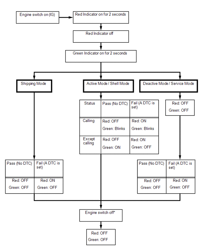
SWITCHING THE CONTRACT MODES
|
Contract Mode | Description |
|---|---|
|
Shipping Mode | Mode the DCM (Telematics Transceiver) is in from the factory and during shipping. In this mode, when engine switch is turned on (IG), the system will automatically attempt to activate into shell mode. |
|
Shell Mode | This mode begins after vehicle has been automatically activated (into shell mode) after arriving at port or leaving the manufacturing plant line. ACN and stolen vehicle locator are available. |
|
Active Mode | This mode begins when the owner's information is provider to telematics and customer signs contract for Safety Connect. All functions of Safety Connect are available. |
|
Service Mode | This mode applies to a service part DCM (Telematics Transceiver) that has not been activated after replacing DCM (Telematics Transceiver) in vehicle. DCM (Telematics Transceiver) has no associated phone numbers. |
|
Deactive Mode | The mode occurs when Safety Connect subscription has been canceled. |
SYSTEM DIAGRAM
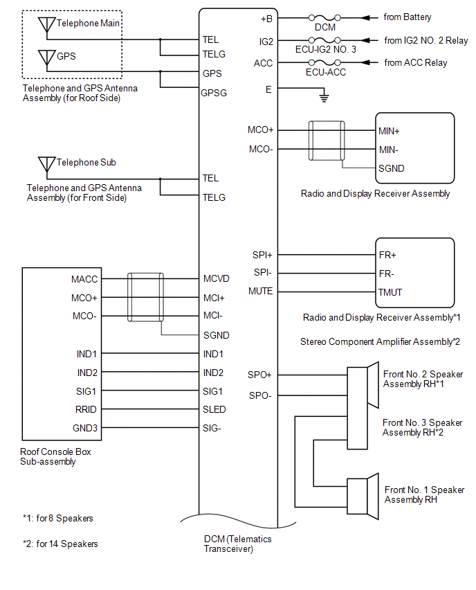
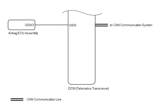
TERMINALS OF ECU
CHECK DCM (TELEMATICS TRANSCEIVER)
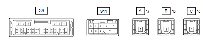
|
*a | Connector Color: Natural (to Telephone Sub Antenna) |
*b | Connector Color: Blue (to Telephone Main Antenna) |
|
*c | Connector Color: Gray (to GPS Antenna) |
- | - |
|
Terminal No. (Symbol) | Wiring Color |
Terminal Description | Condition |
Specified Condition |
|---|---|---|---|---|
|
G9-1 (+B) - G9-4 (E) |
B - W-B | Battery power supply |
Always | 11 to 14 V |
|
G9-2 (SPI+) - G9-4 (E) |
W*3, LA-LG*4 - W-B | Sound signal |
Audio system playing |
A waveform synchronized with sound is output |
|
G9-3 (SPI-) - G9-4 (E) |
B*3, LA-L*4 - W-B | Sound signal |
Audio system playing |
A waveform synchronized with sound is output |
|
G9-4 (E) - Body ground |
W-B - Body ground | Ground |
Always | Below 1 V |
|
G9-5 (SPO+) - G9-4 (E) |
L*3, LA-BE*4 - W-B | Sound signal |
Audio system playing, or Emergency call mode |
A waveform synchronized with sound is output |
|
G9-6 (SPO-) - G9-4 (E) |
Y*3, LA-R*4 - W-B | Sound signal |
Audio system playing, or Emergency call mode |
A waveform synchronized with sound is output |
|
G9-7 (IG2) - G9-4 (E) |
LG - W-B |
IG power supply | Engine switch on (IG) |
11 to 14 V |
|
Engine switch off | Below 1 V | |||
|
G9-8 (ACC) - G9-4 (E) |
B - W-B | ACC power supply |
Engine switch on (ACC) |
11 to 14 V |
|
Engine switch off | Below 1 V | |||
|
G9-9 (SLED) - G9-4 (E) |
SB - W-B |
Manual (SOS) switch illumination power supply |
Engine switch on (ACC) |
11 to 14 V |
|
Engine switch off | Below 1 V | |||
|
G9-11 (IND1) - G9-4 (E) |
P - W-B | Manual (SOS) switch red indicator illumination signal |
For 2 seconds after turning the engine switch on (IG) |
1 to 8.5 V |
|
Engine switch off | Below 1 V | |||
|
G9-12 (IND2) - G9-4 (E) |
LG - W-B |
Manual (SOS) switch green indicator illumination signal |
For 2 seconds after turning the engine switch on (IG) |
1 to 8.5 V |
|
Engine switch off | Below 1 V | |||
|
G9-15 (CANP) | R |
CAN communication signal |
- | - |
|
G9-16 (CANN) | B |
CAN communication signal |
- | - |
|
G9-17 (MUTE) - G9-4 (E) |
BE - W-B |
Mute signal | Audio system playing |
3.5 V or higher |
|
Emergency call mode | Below 1 V | |||
|
G9-18 (MCO+) - G9-4 (E)*1 |
SB - W-B | Sent microphone voice signal |
See "Check Microphone" |
- |
| G9-18 (MCO+) - G9-4 (E)*2 |
SB - W-B | Sent microphone voice signal |
See "Check Microphone" |
- |
| G9-19 (MCO-) - G9-4 (E)*1 |
V - W-B | Sent microphone voice signal |
See "Check Microphone" |
- |
| G9-19 (MCO-) - G9-4 (E)*2 |
V - W-B | Sent microphone voice signal |
See "Check Microphone" |
- |
| G9-24 (GSW) - G9-4 (E) |
W - W-B | Collision detection signal |
Engine switch on (IG) |
Pulse generation (Refer to waveform 1) |
|
G9-26 (SIG-) - G9-4 (E) |
GR - W-B | Ground |
Always | Below 1 V |
|
G9-27 (SIG1) - G9-4 (E) |
B - W-B | Manual (SOS) switch condition signal |
Manual (SOS) switch not pressed |
1.5 to 2.0 V |
|
Manual (SOS) switch pressed |
0.5 to 0.8 V | |||
|
G9-32 (SGND) - G9-4 (E) |
Shield - W-B | Shield ground |
Always | Below 1 V |
|
G9-33 (MCVD) - G9-4 (E) |
B - W-B | Telephone microphone assembly power supply |
Engine switch off | Below 1 V |
|
Engine switch on (ACC) |
4 to 6 V | |||
| G9-34 (MCI+) - G9-4 (E)*1 |
W - W-B | Receive microphone voice signal |
See "Check Microphone" |
- |
| G9-34 (MCI+) - G9-4 (E)*2 |
W - W-B | Receive microphone voice signal |
See "Check Microphone" |
- |
| G9-35 (MCI-) - G9-4 (E)*1 |
R - W-B | Receive microphone voice signal |
See "Check Microphone" |
- |
| G9-35 (MCI-) - G9-4 (E)*2 |
R - W-B | Receive microphone voice signal |
See "Check Microphone" |
- |
(a) Oscilloscope waveform:
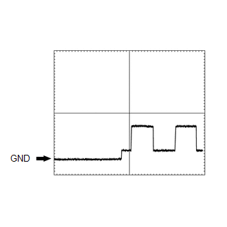
(1) Waveform 1
|
Item | Condition |
|---|---|
|
Tester connection | G9-24 (GSW) - G9-4 (E) |
|
Tool setting | 5.0 V/DIV., 20 ms/DIV. |
|
Vehicle condition | Engine switch on (IG) |
CHECK RADIO AND DISPLAY RECEIVER ASSEMBLY
w/o Navigation System: Click here

w/ Navigation System: Click here
DESCRIPTION
This may occur when the intensity of telephone radio frequency was very weak, or the safety connect system has a malfunction and a DTC is set.
PROCEDURE
| 1. |
CHECK COMMUNICATION SERVICE CONDITION |
(a) Move the vehicle.
(1) If the vehicle is outside the communication service area, move the vehicle to a communication service area, wait for a while and perform the operation again.
OK:
Same problem does not occur.
| OK |  | END |
|
| 2. |
CHECK DTC |
(a) Turn the engine switch off.
(b) Connect the Techstream to the DLC3.
(c) Turn the engine switch on (IG) and wait for 10 seconds.
(d) Turn the Techstream on.
(e) Perform "Health Check" and check for current DTCs.
Click here 
|
Result | Proceed to |
|---|---|
|
DTCs are not output | A |
|
DTCs are output | B |
| B |
| GO TO DIAGNOSTIC TROUBLE CODE CHART |
|
| 3. |
CHECK DCM OPERATION HISTORY |
(a) Check "DCM Operation History".
Click here
|
Result | Proceed to |
|---|---|
|
Signal strength is weak (0 or 1) |
A |
| Communication indicates "Fail" | |
|
No problems with signal strength or communication |
B |
HINT:
If there was a communication problem in the past but the communications are working correctly now, it is possible that the source of the problem was temporary radio interference, or the vehicle may have been outside the service area.
| B | | END |
|
| 4. |
REPLACE DCM (TELEMATICS TRANSCEIVER) |
(a) Replace the DCM (Telematics Transceiver).
Click here
NOTICE:
| NEXT | | PERFORM DCM ACTIVATION |
Toyota Avalon (XX50) 2019-2022 Service & Repair Manual > Ua80e Automatic Transmission / Transaxle: Oil Cooler
Components COMPONENTS ILLUSTRATION *A Type A *B Type B *1 FRONT FENDER APRON SEAL LH *2 FRONT WHEEL OPENING EXTENSION PAD LH *3 FRONT WHEEL OPENING EXTENSION PAD RH *4 NO. 1 ENGINE UNDER COVER *5 REAR ENGINE UNDER COVER LH - - N*m (kgf*cm, ft.*lbf): Specified torque - - ILLUSTRATION *1 BATTERY CLAMP ...