COMPONENTS
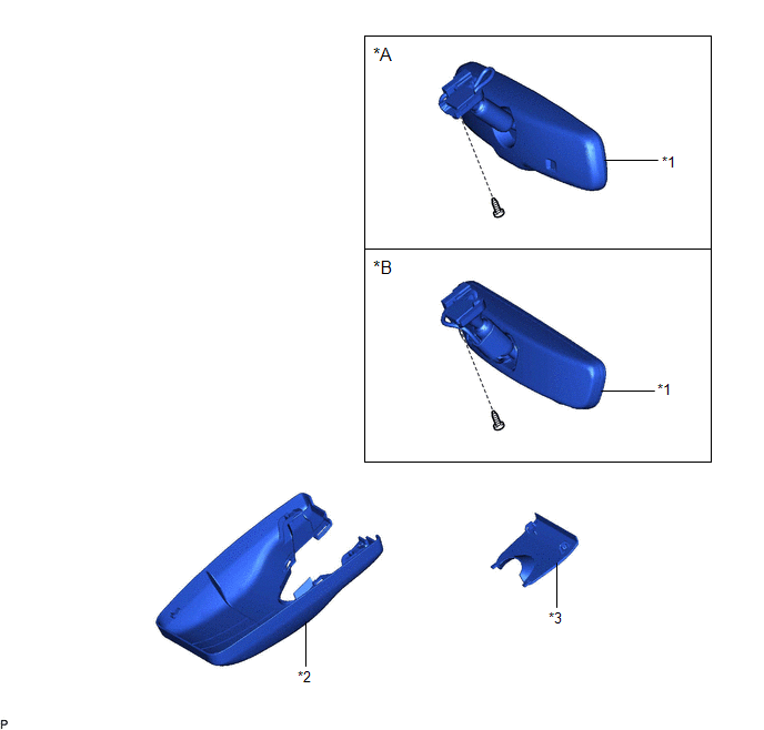
ILLUSTRATION
|
*A | w/o Garage Door Opener System |
*B | w/ Garage Door Opener System |
|
*1 | INNER REAR VIEW MIRROR ASSEMBLY |
*2 | NO. 1 FORWARD RECOGNITION COVER |
|
*3 | NO. 2 FORWARD RECOGNITION COVER |
- | - |
INSPECTION
PROCEDURE
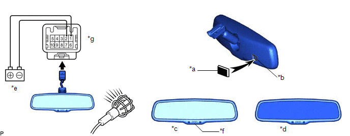
1. INSPECT INNER REAR VIEW MIRROR ASSEMBLY (w/o Garage Door Opener System)
(a) Inspect the operation of the electrochromic inner rear view mirror assembly.
|
*a | Black Colored Tape |
*b | Forward Sensor |
|
*c | Bright |
*d | Dark |
|
*e | Auxiliary Battery |
*f | AUTO Switch |
|
*g | Component without harness connected (Inner Rear View Mirror Assembly) |
- | - |
(1) Connect a positive (+) lead from the auxiliary battery to terminal 1 and a negative (-) lead to terminal 2.
(2) Press the AUTO switch.
(3) Attach black colored tape to the forward sensor to prevent it from sensing.
(4) Light up the mirror with an electric light, and check that the mirror surface changes from bright to dark.
OK:
Mirror surface changes from bright to dark.
(5) Measure the voltage according to the value(s) in the table below.
Standard Voltage:
|
Tester Connection | Condition |
Specified Condition |
|---|---|---|
|
4 - 5 | Inner rear view mirror surface Bright → Dark | Below 1 V → 1.25 V |
If the result is not as specified, replace the inner rear view mirror assembly.
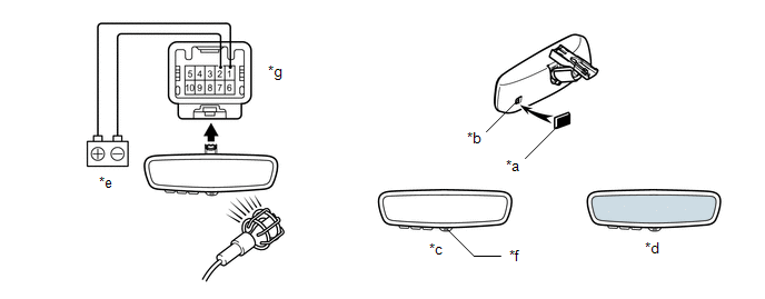
2. INSPECT INNER REAR VIEW MIRROR ASSEMBLY (w/ Garage Door Opener System)
(a) Inspect the operation of the electrochromic inner rear view mirror assembly.
|
*a | Black Colored Tape |
*b | Forward Sensor |
|
*c | Bright |
*d | Dark |
|
*e | Auxiliary Battery |
*f | EC Switch |
|
*g | Component without harness connected (Inner Rear View Mirror Assembly) |
- | - |
(1) Connect a positive (+) lead from the auxiliary battery to terminal 1 and a negative (-) lead to terminal 2.
(2) Press the EC switch.
(3) Attach black colored tape to the forward sensor to prevent it from sensing.
(4) Light up the mirror with an electric light, and check that the mirror surface changes from bright to dark.
OK:
Mirror surface changes from bright to dark.
(5) Measure the voltage according to the value(s) in the table below.
Standard Voltage:
|
Tester Connection | Condition |
Specified Condition |
|---|---|---|
|
4 - 5 | Inner rear view mirror surface Bright → Dark | Below 1 V → 1.25 V |
If the result is not as specified, replace the inner rear view mirror assembly.
INSTALLATION
PROCEDURE
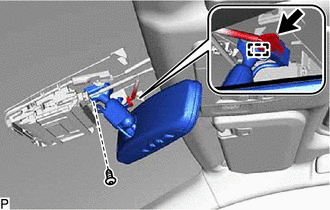
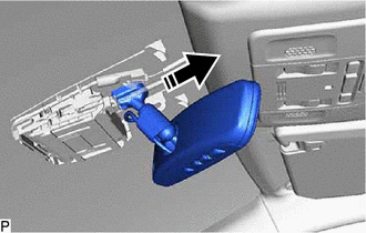
1. INSTALL INNER REAR VIEW MIRROR ASSEMBLY
(a) Slide and temporarily install the inner rear view mirror assembly as shown in the illustration.
 | Install in this Direction |
(b) Using a T20 "TORX" socket wrench, install the inner rear view mirror assembly with the screw.
(c) Engage the clamp.
(d) Connect the connector.
2. INSTALL NO. 1 FORWARD RECOGNITION COVER
Click here 
3. INSTALL NO. 2 FORWARD RECOGNITION COVER
Click here
PROBLEM SYMPTOMS TABLE
HINT:
Use the table below to help determine the cause of problem symptoms. If multiple suspected areas are listed, the potential causes of the symptoms are listed in order of probability in the "Suspected Area" column of the table. Check each symptom by checking the suspected areas in the order they are listed. Replace parts as necessary.
Inner Rear View Mirror|
Symptom | Suspected Area |
Link |
|---|---|---|
|
Auto glare-resistant EC mirror does not operate |
ECU-IG1 NO. 3 fuse | - |
|
Inner rear view mirror assembly |
| |
|
Wire harness or connector |
- |
REMOVAL
CAUTION / NOTICE / HINT
The necessary procedures (adjustment, calibration, initialization, or registration) that must be performed after parts are removed and installed, or replaced during inner rear view mirror assembly removal/installation are shown below.
Necessary Procedures After Procedure Performed (for Gasoline Model)|
Replaced Part or Performed Procedure |
Necessary Procedure | Effect/Inoperative Function when Necessary Procedure not Performed |
Link |
|---|---|---|---|
| Replacement of inner rear view mirror assembly |
Register codes in the garage door opener system |
Garage door opener system |
|
|
Replaced Part or Performed Procedure |
Necessary Procedure | Effect/Inoperative Function when Necessary Procedure not Performed |
Link |
|---|---|---|---|
| Replacement of inner rear view mirror assembly |
Register codes in the garage door opener system |
Garage door opener system |
|
PROCEDURE
1. REMOVE NO. 2 FORWARD RECOGNITION COVER
Click here

2. REMOVE NO. 1 FORWARD RECOGNITION COVER
Click here
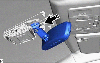
3. REMOVE INNER REAR VIEW MIRROR ASSEMBLY
| (a) Disconnect the connector. |
|
(b) Disengage the clamp.
(c) Using a T20 "TORX" socket wrench, remove the screw.
(d) Slide the inner rear view mirror assembly as shown in the illustration to remove it.
 |
Remove in this Direction |
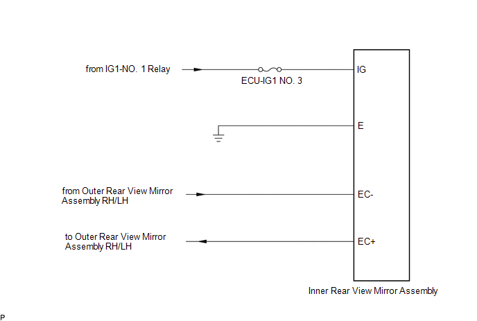
SYSTEM DIAGRAM
Toyota Avalon (XX50) 2019-2022 Service & Repair Manual > 2gr-fks Engine Mechanical: Cylinder Head Gasket
Components COMPONENTS ILLUSTRATION *A Type A *B Type B *1 IGNITION COIL ASSEMBLY *2 VACUUM PUMP ASSEMBLY *3 V-RIBBED BELT *4 GENERATOR ASSEMBLY *5 COMPRESSOR ASSEMBLY WITH MAGNETIC CLUTCH *6 V-RIBBED BELT TENSIONER ASSEMBLY *7 WATER PUMP PULLEY *8 NO. 2 IDLER PULLEY SUB-ASSEMBLY *9 ENGINE OIL LEVEL ...