DESCRIPTION This is the power source circuit for the mobile wireless charger cradle assembly. WIRING DIAGRAM 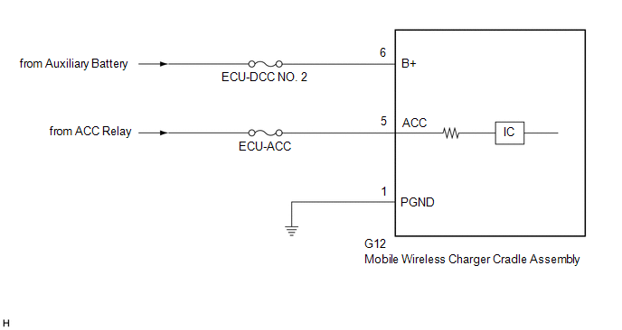 CAUTION / NOTICE / HINT NOTICE: Inspect the fuses for circuits related to this system before performing the following procedure. PROCEDURE
(a) Disconnect the G12 mobile wireless charger cradle assembly connector. (b) Measure the resistance according to the value(s) in the table below. Standard Resistance:
(c) Measure the voltage according to the value(s) in the table below. Standard Voltage:
|
Toyota Avalon (XX50) 2019-2022 Service & Repair Manual > Motor Generator Control System: Drive Motor "A" Circuit Current Out of Range (P0BFF1D)
DTC SUMMARY MALFUNCTION DESCRIPTION This DTC is stored when the motor generator control system is malfunctioning and current does not flow as commanded. The cause of this malfunction may be one of the following: Area Main Malfunction Description Inside of inverter Inverter with converter assembly in ...


