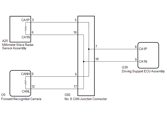
DESCRIPTION The driving
support ECU assembly is connected to the millimeter wave radar sensor
assembly, forward recognition camera and skid control ECU (brake
actuator assembly) via CAN communication. If communication with the
millimeter wave radar sensor assembly, forward recognition camera or
skid control ECU (brake actuator assembly) stops, the driving support
ECU assembly stores DTC U1104. |
DTC No. | Detection Item |
DTC Detection Condition | Trouble Area | |
U1104 | Lost Communication with Driving Support ECU |
Any of the following conditions is met:
- When the engine switch is on (IG), a communication error between the
driving support ECU assembly and the millimeter wave radar sensor
assembly is detected for approximately 0.2 seconds.
- When the engine switch is on (IG), a communication error between the
driving support ECU assembly and the forward recognition camera is
detected for approximately 0.3 seconds.
- When the engine switch is on (IG), a communication error between the
driving support ECU assembly and the skid control ECU (brake actuator
assembly) is detected for approximately 1.5 seconds.
|
- CAN communication system
- CAN bus line
- Front camera system
- Electronically controlled brake system
- Millimeter wave radar sensor assembly
- Forward recognition camera
- Driving support ECU assembly
| DTC Detection Conditions: | |
Vehicle Condition | |
Pattern 1 | Pattern 2 |
Pattern 3 | |
Diagnosis Condition | Engine switch is on (IG) |
○ | ○ |
○ | |
Malfunction Status | A communication error between the driving support ECU assembly and the millimeter wave radar sensor assembly is detected |
○ | - |
- | | A communication error between the driving support ECU assembly and the forward recognition camera is detected |
- | ○ |
- | | A communication error between the driving support ECU assembly and the skid control ECU (brake actuator assembly) is detected |
- | - |
○ | |
Detection Time | Approximately 0.2 seconds or more |
Approximately 0.3 seconds or more |
Approximately 1.5 seconds or more | |
Number of Trips | 1 trip |
1 trip | 1 trip |
HINT: DTC will be stored when conditions of any pattern in the table above are met. WIRING DIAGRAM
 CAUTION / NOTICE / HINT
NOTICE:
- Inspect the fuses for circuits related to this system before performing the following procedure.
- Before measuring the resistance of the CAN bus, turn the engine switch
off and leave the vehicle for 1 minute or more without operating the key
or any switches, or opening or closing the doors. After that,
disconnect the cable from the negative (-) battery terminal and leave
the vehicle for 1 minute or more before measuring the resistance.
- After turning the engine switch off, waiting time may be required before
disconnecting the cable from the negative (-) battery terminal.
Therefore, make sure to read the disconnecting the cable from the
negative (-) battery terminal notices before proceeding with work.
Click here 
- When replacing the driving support ECU assembly, always replace it with a
new one. If a driving support ECU assembly which was installed to
another vehicle is used, the information stored in the driving support
ECU assembly will not match the information from the vehicle. As a
result, a DTC may be stored.
- When replacing the forward recognition camera, always replace it with a
new one. If a forward recognition camera which was installed to another
vehicle is used, the information stored in the forward recognition
camera will not match the information from the vehicle. As a result, a
DTC may be stored.
- If the forward recognition camera has been replaced with a new one, be sure to perform forward recognition camera adjustment.
Click here
- When replacing the millimeter wave radar sensor assembly, always replace
it with a new one. If a millimeter wave radar sensor assembly which was
installed to another vehicle is used, the information stored in the
millimeter wave radar sensor assembly will not match the information
from the vehicle. As a result, a DTC may be stored.
- When the millimeter wave radar sensor assembly is replaced with a new
one, adjustment of the radar sensor beam axis must be performed.
Click here
- Confirm that the connectors are securely connected, as a partially connected connector can cause this DTC to be stored.
PROCEDURE |
1. | READ VALUE USING TECHSTREAM (CAN BUS CHECK) |
(a) Connect the Techstream to the DLC3. (b) Turn the engine switch on (IG).
(c) Turn the Techstream on. (d) Enter the following menus: System Select / Can Bus Check.
Click here CAN Bus Check
|
Result | Proceed to | |
All of the ECUs and sensors that are currently connected to the CAN communication system are displayed |
A | | None
of the ECUs and sensors that are currently connected to the CAN
communication system are displayed, or some of them are not displayed |
B |
| B |
 | GO TO CAN COMMUNICATION SYSTEM |
|
A |
 | |
(a) Check for DTCs. Chassis > Front Recognition Camera > Trouble Codes
|
Result | Proceed to | |
DTCs are not output | A | |
Only DTC U0235 is output |
B | | Only DTC U1104 is output |
C | | DTC U0235 and U1104 are output |
D |
| B |
| GO TO STEP 6 |
| C |
| REPLACE DRIVING SUPPORT ECU ASSEMBLY |
| D |
| GO TO STEP 7 |
|
A | |
| |
(a) Check for DTCs. Chassis > ABS/VSC/TRAC/EPB > Trouble Codes
|
Result | Proceed to | |
Electronically controlled brake system DTCs are not output |
A | | Electronically controlled brake system DTCs are output |
B |
| B |
| GO TO ELECTRONICALLY CONTROLLED BRAKE SYSTEM |
|
A | |
| |
| 4. |
TEST MODE INSPECTION (ELECTRONICALLY CONTROLLED BRAKE SYSTEM) |
NOTICE: Perform Test Mode (Signal Check) with the vehicle stopped.
HINT: When
entering Test Mode (Signal Check), the skid control ECU (brake actuator
assembly) communicates with the driving support ECU assembly to judge
whether the vehicle is equipped with the pre-collision system.
Therefore, do not exit Test Mode (Signal Check) within 5 seconds of
entering Test Mode (Signal Check). (a) Procedure to enter Test Mode (Signal Check)
(1) Turn the engine switch off. (2) Check that the steering wheel is centered.
(3) Apply the parking brake. (4) Check that the shift lever is in P.
(5) Connect the Techstream to the DLC3. (6) Turn the engine switch on (IG).
(7) Turn the Techstream on. (8)
Switch the skid control ECU (brake actuator assembly) to Test Mode
(Signal Check) using the Techstream. Enter the following menus: Chassis /
ABS/VSC/TRAC/EPB / Utility / Signal Check. HINT: Do
not exit Test Mode (Signal Check) within 5 seconds of entering Test
Mode (Signal Check). If Test Mode (Signal Check) is exited within 5
seconds of entering Test Mode (Signal Check), DTC U1104 may be stored.
If DTC U1104 is output after exiting Test Mode (Signal Check), enter
Test Mode (Signal Check) again, wait at least 5 seconds, then recheck
for DTCs. Chassis > ABS/VSC/TRAC/EPB > Utility
|
Tester Display | | Signal Check |
(9)
Check that the ABS warning and slip indicator lights come on for
several seconds and the ABS warning, slip indicator and parking brake
indicator lights blink in the Test Mode pattern.
HINT:
- If the ABS warning, slip indicator and parking brake indicator lights do
not blink, inspect the ABS warning, slip indicator and parking brake
indicator light circuits.
- While the parking brake is engaged, the parking brake indicator light illuminates but does not blink in the Test Mode pattern.
(b) End of Test Mode (Signal Check) (1) End Test Mode (signal check) using the Techstream
- Turn the engine switch off and enter normal mode.
- Remove the Techstream.
|
NEXT | |
| |
(a) Clear the DTCs. Body Electrical > Pre-Collision 2 > Clear DTCs
(b) Make sure that the DTC detection conditions are met. HINT: If the detection conditions are not met, the system cannot detect the malfunction.
(c) Check for DTCs. Body Electrical > Pre-Collision 2 > Trouble Codes
|
Result | Proceed to | |
DTC U1104 is not output |
A | | DTC U1104 is output |
B |
| A |
| END |
| B |
| REPLACE DRIVING SUPPORT ECU ASSEMBLY |
(a) Turn the engine switch off.
(b) Disconnect the cable from the negative (-) battery terminal.
| (c) Disconnect the O5 forward recognition camera connector. |
 |
|
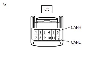
*a | Front view of wire harness connector
(to Forward Recognition Camera) | | |
(d) Measure the resistance according to the value(s) in the table below.
Standard Resistance: |
Tester Connection | Condition |
Specified Condition | |
O5-6 (CANH) - O5-12 (CANL) |
Cable disconnected from negative (-) battery terminal |
108 to 132 Ω | HINT: If the result is not as specified, a malfunction in a CAN communication line is suspected.
(e) Connect the O5 forward recognition camera connector.
| OK |
| REPLACE MILLIMETER WAVE RADAR SENSOR ASSEMBLY |
| NG |
| REPAIR OR REPLACE HARNESS OR CONNECTOR (CAN BUS LINE) |
(a) Turn the engine switch off.
(b) Disconnect the cable from the negative (-) battery terminal.
| (c) Disconnect the O5 forward recognition camera connector. |
|
|
|
*a | Front view of wire harness connector
(to Forward Recognition Camera) | | |
(d) Measure the resistance according to the value(s) in the table below.
Standard Resistance: |
Tester Connection | Condition |
Specified Condition | |
O5-6 (CANH) - O5-12 (CANL) |
Cable disconnected from negative (-) battery terminal |
108 to 132 Ω | HINT: If the result is not as specified, a malfunction in a CAN communication line is suspected.
(e) Connect the O5 forward recognition camera connector.
| OK |
| REPLACE FORWARD RECOGNITION CAMERA |
| NG |
| REPAIR OR REPLACE HARNESS OR CONNECTOR (CAN BUS LINE) | | 

