PARTS LOCATION ILLUSTRATION 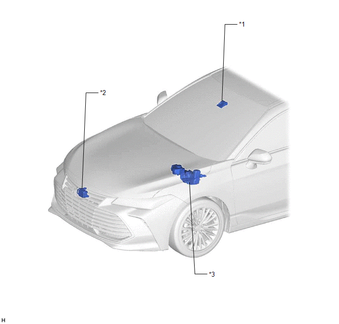
ILLUSTRATION 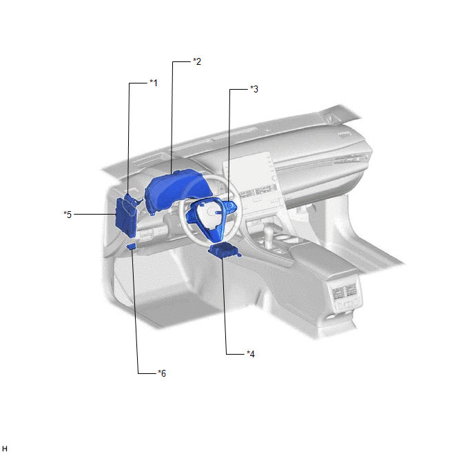
ILLUSTRATION 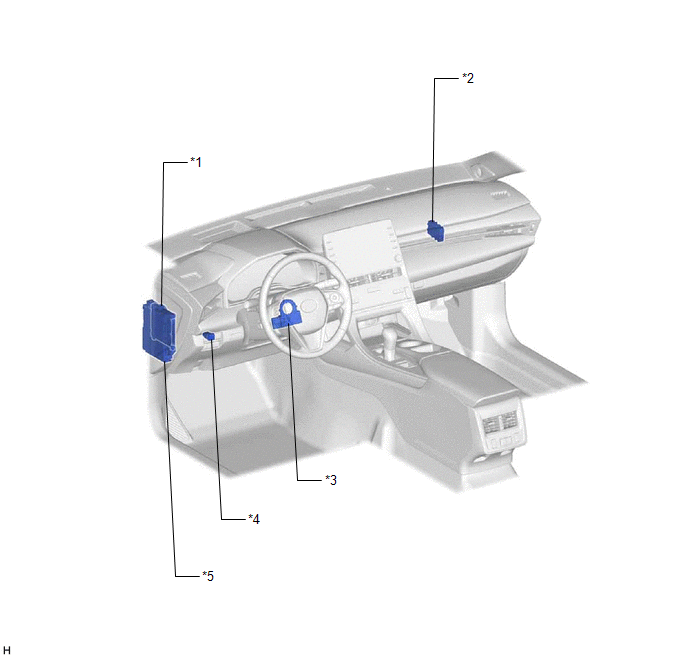
|
Toyota Avalon (XX50) 2019-2022 Service & Repair Manual > Panoramic View Monitor System(for Gasoline Model): Lost Communication with ECM / PCM "A" (U0100,U0126,U0129,U0140,U0163,U0233)
DESCRIPTION These DTCs are stored if there is a malfunction in the CAN communication system connected to the parking assist ECU. These DTCs are stored if there is a malfunction in the CAN communication system connected to the television camera assembly. HINT: If CAN communication system DTCs are sto ...


