Toyota Avalon (XX50) 2019-2022 Service & Repair Manual: System Diagram

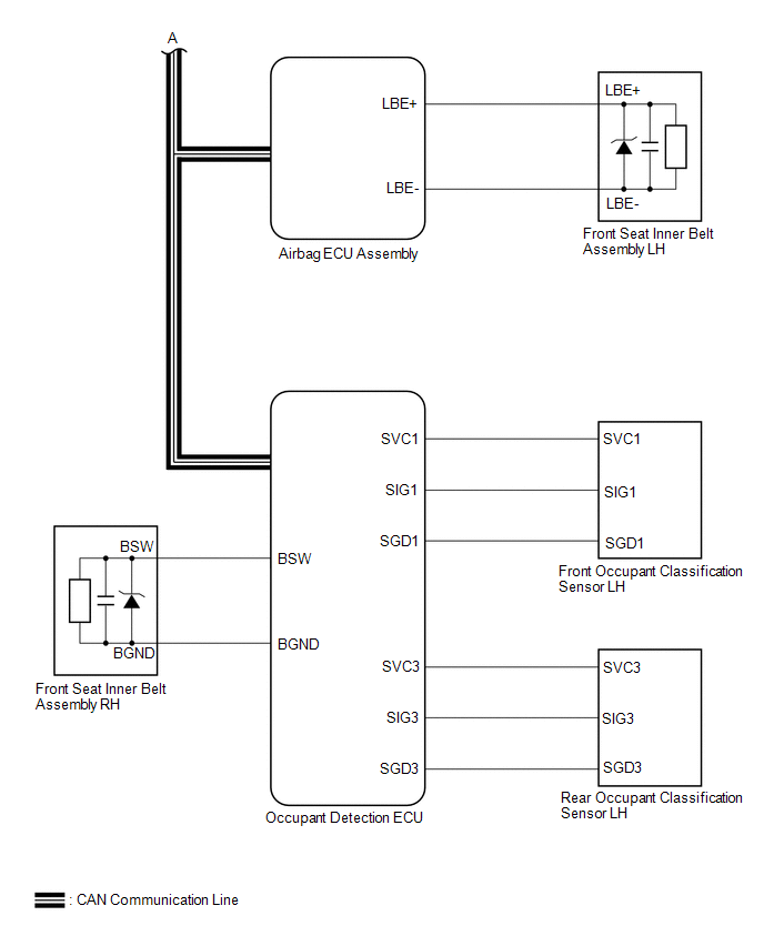
SYSTEM DIAGRAM

FRONT SEAT BELT WARNING
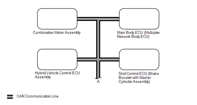
Communication Table

Sender

Receiver

Signal

Communication Method

Airbag ECU assembly

Main body ECU (multiplex network body ECU)

Front seat inner belt assembly LH buckle switch

CAN

Combination meter assembly

  • Front seat inner belt assembly RH buckle switch
  • Occupant detection

Skid control ECU (brake booster with master cylinder assembly)

Combination meter assembly

Vehicle speed

Hybrid vehicle control ECU assembly

Combination meter assembly

Shift position

Occupant detection ECU

Airbag ECU assembly

  • Front seat inner belt assembly RH buckle switch
  • Occupant detection

Main body ECU (multiplex network body ECU)

Combination meter assembly

  • Front seat inner belt assembly LH buckle switch
  • Parking brake switch

REAR SEAT BELT WARNING
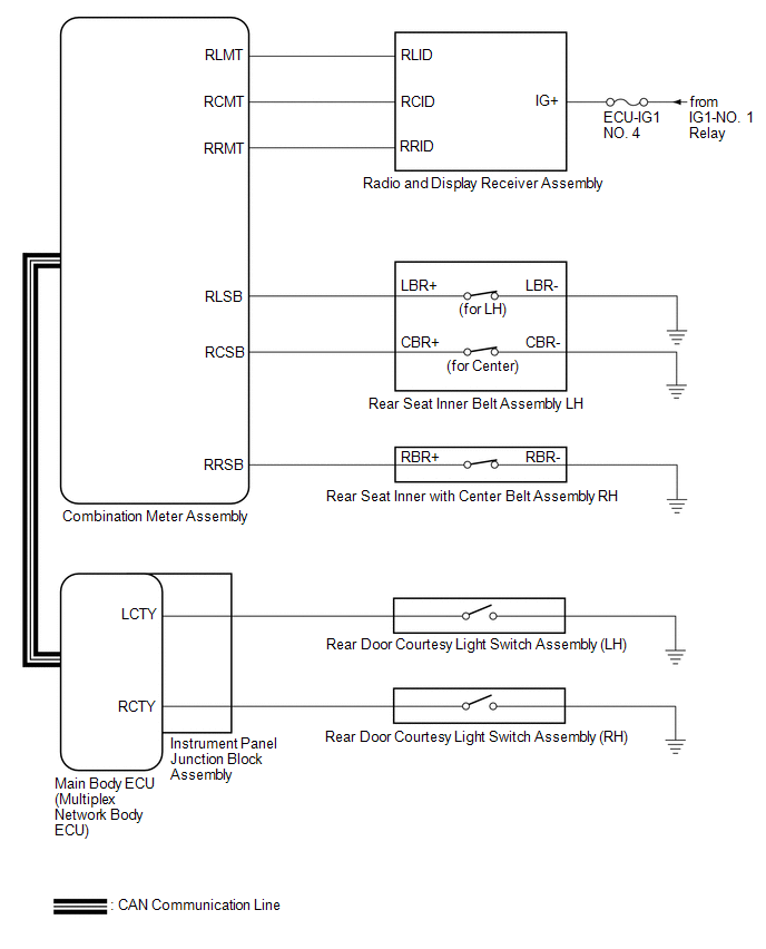
Communication Table

Sender

Receiver

Signal

Communication Method

Main body ECU (multiplex network body ECU)

Combination meter assembly

  • Rear door courtesy light switch (LH/RH)
  • Parking brake switch

CAN

    System Description

    Terminals Of Ecu

    See More:

    Toyota Avalon (XX50) 2019-2022 Service & Repair Manual > Electric Parking Brake System(for Hv Model): Brake System Malfunction (C13A9)
    DESCRIPTION The parking brake ECU (brake actuator assembly) receives the wheel speed signal of each wheel from the skid control ECU (brake booster with master cylinder assembly) via CAN communication. This DTC is stored when a malfunction occurs in the skid control ECU (brake booster with master cyl ...

    Toyota Avalon (XX50) 2019-2022 Owners Manual

    Toyota Avalon (XX50) 2019-2022 Service & Repair Manual

    © 2024 Copyright www.tavalon.net
    0.0197