CUSTOMIZE PARAMETERS
CUSTOMIZE SEAT BELT WARNING SYSTEM
NOTICE:
HINT:
The following items can be customized.
(a) Customizing with the Techstream
(1) Connect the Techstream to the DLC3.
(2) Turn the power switch on (IG).
(3) Turn the Techstream on.
(4) Enter the following menus: Customize Setting / Warning.
(5) Select the setting by referring to the table below.
Warning|
Tester Display | Description |
Default | Setting |
ECU |
|---|---|---|---|---|
| Driver Seatbelt Warning Buzzer Function |
Enables sounding of the driver seat belt warning buzzer |
ON | $00:OFF,$01:ON |
Combination meter assembly |
|
Passenger Seatbelt Warning Buzzer Function |
Enables sounding of the front passenger seat belt warning buzzer |
ON | $00:OFF,$01:ON |
Combination meter assembly |
|
Rear Right Seatbelt Warning Buzzer Function |
Function to sound the rear RH seat belt warning buzzer |
ON | $00:OFF,$01:ON |
Combination meter assembly |
|
Rear Left Seatbelt Warning Buzzer Function |
Function to sound the rear LH seat belt warning buzzer |
ON | $00:OFF,$01:ON |
Combination meter assembly |
|
Rear Center Seatbelt Warning Buzzer Function |
Function to sound the rear center seat belt warning buzzer |
ON | $00:OFF,$01:ON |
Combination meter assembly |
HINT:
These settings are only valid when the vehicle is driven at approximately 20 km/h (12 mph) or more.
DATA LIST / ACTIVE TEST
DATA LIST
NOTICE:
In the following table, the values listed under "Normal Condition" are reference values. Do not depend solely on these reference values when deciding whether a part is faulty or not.
HINT:
Using the Techstream to read the Data List allows the values or states of switches, sensors, actuators and other items to be read without removing any parts. This non-intrusive inspection can be very useful because intermittent conditions or signals may be discovered before parts or wiring is disturbed. Reading the Data List information early in troubleshooting is one way to save diagnostic time.
(a) Connect the Techstream to the DLC3.
(b) Turn the power switch on (IG).
(c) Turn the Techstream on.
(d) Enter the following menus: Body Electrical / Combination Meter, Occupant Detection, SRS Airbag or Main Body / Data List.
(e) Read the Data List according to the display on the Techstream.
Body Electrical > Combination Meter > Data List|
Tester Display | Measurement Item |
Range | Normal Condition |
Diagnostic Note |
|---|---|---|---|---|
|
Rear Right Seat Buckle / Occupant Detection Warning Switch |
Rear seat inner with center belt RH buckle signal |
ON or OFF | OFF: Rear RH seat belt fastened ON: Rear RH seat belt not fastened |
- |
| Rear Left Seat Buckle / Occupant Detection Warning Switch |
Rear seat inner belt LH (for LH) buckle signal |
ON or OFF | OFF: Rear LH seat belt (for LH) fastened ON: Rear LH seat belt (for LH) not fastened |
- |
| Rear Center Seat Buckle / Occupant Detection Warning Switch |
Rear seat inner belt LH (for center) buckle signal |
ON or OFF | OFF: Rear LH seat belt (for center) fastened ON: Rear LH seat belt (for center) not fastened |
- |
| Driver Seatbelt Warning Buzzer Function |
Driver seat belt warning buzzer |
ON or OFF | Customized setting displayed |
- |
| Passenger Seatbelt Warning Buzzer Function |
Front passenger seat belt warning buzzer |
ON or OFF | Customized setting displayed |
- |
| Rear Right Seatbelt Warning Buzzer Function |
Rear RH seat belt warning buzzer |
ON or OFF | Customized value displayed |
- |
| Rear Left Seatbelt Warning Buzzer Function |
Rear LH seat belt warning buzzer |
ON or OFF | Customized value displayed |
- |
| Rear Center Seatbelt Warning Buzzer Function |
Rear center seat belt warning buzzer |
ON or OFF | Customized value displayed |
- |
|
Tester Display | Measurement Item |
Range | Normal Condition |
Diagnostic Note |
|---|---|---|---|---|
|
Passenger Buckle SW | Front passenger buckle switch |
Unset, Set or NG | Unset: Seat belt not fastened Set: Seat belt fastened NG: Data is not determined |
- |
|
Tester Display | Measurement Item |
Range | Normal Condition |
Diagnostic Note |
|---|---|---|---|---|
|
Left side Buckle SW | LH buckle switch |
Unset, Set or NG | Unset: Seat belt not fastened Set: Seat belt fastened NG: Data is not determined |
- |
| Right side Buckle SW |
RH buckle switch | Unset, Set or NG |
Unset: Seat belt not fastened Set: Seat belt fastened NG: Data is not determined |
- |
|
Tester Display | Measurement Item |
Range | Normal Condition |
Diagnostic Note |
|---|---|---|---|---|
|
RR Door Courtesy SW | Rear door courtesy light switch RH |
ON or OFF | ON: Rear door RH open OFF: Rear door RH closed |
- |
| RL Door Courtesy SW |
Rear door courtesy light switch LH |
ON or OFF | ON: Rear door LH open OFF: Rear door LH closed |
- |
ACTIVE TEST
HINT:
Using the Techstream to perform Active Tests allows relays, VSVs, actuators and other items to be operated without removing any parts. This non-intrusive functional inspection can be very useful because intermittent operation may be discovered before parts or wiring is disturbed. Performing Active Tests early in troubleshooting is one way to save diagnostic time. Data List information can be displayed while performing Active Tests.
(a) Connect the Techstream to the DLC3.
(b) Turn the power switch on (IG).
(c) Turn the Techstream on.
(d) Enter the following menus: Body Electrical / Combination Meter / Active Test.
(e) Perform the Active Test according to the display on the Techstream.
Body Electrical > Combination Meter > Active Test|
Tester Display | Measurement Item |
Control Range | Diagnostic Note |
|---|---|---|---|
|
Buzzer Operation (800Hz, Vol L, W/ Damping) |
Combination meter buzzer
| ON |
- |
| Buzzer Operation (800Hz, Vol L, W/O Damping) |
Combination meter buzzer
| ON |
- |
| Buzzer Operation (800Hz, Vol S, W/ Damping) |
Combination meter buzzer
| ON |
- |
| Buzzer Operation (800Hz, Vol S, W/O Damping) |
Combination meter buzzer
| ON |
- |
| Driver Side Seat Belt Warning |
Driver side seat belt warning light |
OFF/ON | - |
|
Passenger Side Seat Belt Warning |
Front passenger side seat belt warning light |
OFF/ON | Not applicable to this vehicle |
|
Rear Seat Belt Warning |
Rear seat belt warning light |
OFF/ON | - |
DIAGNOSIS SYSTEM
CHECK DLC3
(a) Check the DLC3.
Click here 
INSPECT AUXILIARY BATTERY VOLTAGE
(a) Measure the auxiliary battery voltage with the power switch off.
Standard Voltage:
11 to 14 V
If the voltage is below 11 V, recharge or replace the auxiliary battery.
DESCRIPTION
The seat belt warning light on the combination meter assembly illuminates, blinks or turns off in accordance with the state of the front seat inner belt assembly LH.
WIRING DIAGRAM
CAUTION / NOTICE / HINT
NOTICE:
The seat belt warning system uses the CAN communication system. First, confirm that there are no malfunctions in the CAN communication system. Refer to How to Proceed with Troubleshooting.
Click here

HINT:
The seat belt warning light on the combination meter assembly is used for both the driver seat and front passenger seat. Check that the operation of the seat belt warning light is normal first.
Click here
If the seat belt warning light does not operate for both the driver seat and front passenger seat, replace the combination meter assembly.
Click here
PROCEDURE
| 1. |
CHECK DTC OUTPUT (AIRBAG SYSTEM) |
(a) Clear the DTCs.
Body Electrical > SRS Airbag > Clear DTCs(b) Check for DTCs.
Body Electrical > SRS Airbag > Trouble Codes|
Result | Proceed to |
|---|---|
|
DTCs are not output | A |
|
DTCs are output | B |
| B |
 | GO TO AIRBAG SYSTEM |
|
| 2. |
READ VALUE USING TECHSTREAM |
(a) Connect the Techstream to the DLC3.
(b) Turn the power switch on (IG).
(c) Turn the Techstream on.
(d) Enter the following menus: Body Electrical / SRS Airbag / Data List.
(e) Read the Data List according to the display on the Techstream.
Body Electrical > SRS Airbag > Data List|
Tester Display | Measurement Item |
Range | Normal Condition |
Diagnostic Note |
|---|---|---|---|---|
|
Left side Buckle SW | LH buckle switch |
Unset, Set or NG | Unset: Seat belt not fastened Set: Seat belt fastened NG: Data is not determined |
- |
|
Tester Display |
|---|
| Left side Buckle SW |
|
Result | Proceed to |
|---|---|
|
Unset or Set is displayed on the Techstream according to the driver seat belt condition |
A |
| Unset or Set is not displayed correctly on the Techstream according to the driver seat belt condition |
B |
| NG is displayed on the Techstream |
C |
| A |
| USE SIMULATION METHOD TO CHECK |
| B |
| REPLACE FRONT SEAT INNER BELT ASSEMBLY LH |
| C |
| REPLACE AIR BAG ECU ASSEMBLY |
DESCRIPTION
When the power switch is turned on (IG), the occupant detection ECU sends signals to the airbag ECU assembly to indicate the state of the front seat inner belt assembly RH and also whether the front passenger seat is occupied. The airbag ECU assembly sends those signals to the combination meter assembly via CAN communication. The seat belt warning light on the combination meter assembly illuminates, blinks or turns off in accordance with these signals.
WIRING DIAGRAM
CAUTION / NOTICE / HINT
NOTICE:
The seat belt warning system uses the CAN communication system. First, confirm that there are no malfunctions in the CAN communication system. Refer to How to Proceed with Troubleshooting.
Click here

HINT:
The seat belt warning light on the combination meter assembly is used for both the driver seat and front passenger seat. Check that the operation of the seat belt warning light is normal first.
Click here
If the seat belt warning light does not operate for both the driver seat and front passenger seat, replace the combination meter.
Click here
PROCEDURE
| 1. |
CHECK DTC OUTPUT (OCCUPANT CLASSIFICATION SYSTEM) |
(a) Clear the DTCs.
Body Electrical > Occupant Detection > Clear DTCs(b) Check for DTCs.
Body Electrical > Occupant Detection > Trouble Codes|
Result | Proceed to |
|---|---|
|
DTCs are not output | A |
|
DTCs are output | B |
| B |
 | GO TO OCCUPANT CLASSIFICATION SYSTEM |
|
| 2. |
CHECK DTC OUTPUT (AIRBAG SYSTEM) |
(a) Clear the DTCs.
Body Electrical > SRS Airbag > Clear DTCs(b) Check for DTCs.
Body Electrical > SRS Airbag > Trouble Codes|
Result | Proceed to |
|---|---|
|
DTCs are not output | A |
|
DTCs are output | B |
| B |
| GO TO AIRBAG SYSTEM |
|
| 3. |
READ VALUE USING TECHSTREAM |
(a) Connect the Techstream to the DLC3.
(b) Turn the power switch on (IG).
(c) Turn the Techstream on.
(d) Enter the following menus: Body Electrical / Occupant Detection / Data List.
(e) Read the Data List according to the display on the Techstream.
Body Electrical > Occupant Detection > Data List|
Tester Display | Measurement Item |
Range | Normal Condition |
Diagnostic Note |
|---|---|---|---|---|
|
Passenger Buckle SW | Front passenger buckle switch |
Unset, Set or NG | Unset: Seat belt not fastened Set: Seat belt fastened NG: Data is not determined |
- |
|
Tester Display |
|---|
| Passenger Buckle SW |
|
Result | Proceed to |
|---|---|
|
Unset or Set is displayed on the Techstream according to the front passenger seat belt condition |
A |
| Unset or Set is not displayed correctly on the Techstream according to the front passenger seat belt condition |
B |
| NG is displayed on the Techstream |
C |
| B |
| REPLACE FRONT SEAT INNER BELT ASSEMBLY RH |
| C |
| REPLACE OCCUPANT DETECTION ECU |
|
| 4. |
READ VALUE USING TECHSTREAM |
(a) Connect the Techstream to the DLC3.
(b) Turn the power switch on (IG).
(c) Turn the Techstream on.
(d) Enter the following menus: Body Electrical / SRS Airbag / Data List.
(e) Read the Data List according to the display on the Techstream.
Body Electrical > SRS Airbag > Data List|
Tester Display | Measurement Item |
Range | Normal Condition |
Diagnostic Note |
|---|---|---|---|---|
|
Right side Buckle SW | RH buckle switch |
Unset, Set or NG | Unset: Seat belt not fastened Set: Seat belt fastened NG: Data is not determined |
- |
|
Tester Display |
|---|
| Right side Buckle SW |
|
Result | Proceed to |
|---|---|
|
Unset or Set is displayed on the Techstream according to the front passenger seat belt condition |
A |
| B |
| A |
| USE SIMULATION METHOD TO CHECK |
| B |
| REPLACE AIR BAG ECU ASSEMBLY |
CAUTION / NOTICE / HINT
HINT:
PROCEDURE
|
1. | VEHICLE BROUGHT TO WORKSHOP |
|
| 2. |
CUSTOMER PROBLEM ANALYSIS |
(a) Interview the customer to confirm the problem.
Click here 
|
| 3. |
PRE-CHECK |
(a) Measure the auxiliary battery voltage with the power switch off.
Standard Voltage:
11 to 14 V
If the voltage is below 11 V, recharge or replace the auxiliary battery before proceeding to the next step.
(b) Check the fuses and relays.
(c) Check the connector connections and terminals to make sure that there are no abnormalities such as loose connections, deformation, etc.
|
| 4. |
CHECK COMMUNICATION FUNCTION OF CAN COMMUNICATION SYSTEM* |
(a) Using the Techstream, check for CAN communication system DTCs.
Click here
|
Result | Proceed to |
|---|---|
|
CAN DTCs are not output |
A |
| CAN DTCs are output |
B |
| B |
 | GO TO CAN COMMUNICATION SYSTEM |
|
| 5. |
CHECK DTC OUTPUT (AIRBAG SYSTEM)* |
(a) Clear the DTCs.
Body Electrical > SRS Airbag > Clear DTCs(b) Check for DTCs.
Body Electrical > SRS Airbag > Trouble Codes|
Result | Proceed to |
|---|---|
|
DTCs are not output | A |
|
DTCs are output | B |
| B |
| GO TO AIRBAG SYSTEM |
|
| 6. |
CHECK DTC OUTPUT (OCCUPANT CLASSIFICATION SYSTEM)* |
(a) Clear the DTCs.
Body Electrical > Occupant Detection > Clear DTCs(b) Check for DTCs.
Body Electrical > Occupant Detection > Trouble Codes|
Result | Proceed to |
|---|---|
|
DTCs are not output | A |
|
DTCs are output | B |
| B |
| GO TO OCCUPANT CLASSIFICATION SYSTEM |
|
| 7. |
CHECK COMBINATION METER ASSEMBLY |
(a) Check the operation of the speedometer, shift indicator and brake warning light on the combination meter assembly.
OK:
The speedometer, shift indicator and brake warning light on the combination meter assembly operate normally.
| NG | | GO TO METER / GAUGE SYSTEM |
|
| 8. |
PROBLEM SYMPTOMS TABLE |
(a) Refer to Problem Symptoms Table.
Click here
|
Result | Proceed to |
|---|---|
|
Fault is not listed in Problem Symptoms Table |
A |
| Fault is listed in Problem Symptoms Table |
B |
| B |
| GO TO STEP 10 |
|
| 9. |
OVERALL ANALYSIS AND TROUBLESHOOTING* |
(a) Data List / Active Test
Click here
(b) Terminals of ECU
Click here
(c) On-vehicle Inspection
Click here
|
| 10. |
REPAIR OR REPLACE |
|
| 11. |
CONFIRMATION TEST |
| NEXT | | END |
ON-VEHICLE INSPECTION
PROCEDURE
1. INSPECT DRIVER SEAT BELT WARNING LIGHT
HINT:
The seat belt warning light on the combination meter assembly is used for both the driver seat and front passenger seat.
(a) Turn the power switch on (IG).
(b) When the driver seat belt is not fastened, check that the seat belt warning light on the combination meter assembly blinks for 6 seconds.
Check that the seat belt warning light on the combination meter assembly changes from blinking to illuminated.
(c) Lift the vehicle using a swing arm type lift.
Click here

(d) Turn the power switch on (READY).
(e) Check the state of the seat belt warning light on the combination meter assembly under the following conditions:
(1) Step 1:
When the driver seat belt is not fastened, the shift lever is in any position other than P and the parking brake is released, check that the seat belt warning light on the combination meter assembly blinks.
(2) Step 2:
When the driver seat belt is not fastened and the vehicle is driven at approximately 20 km/h (12 mph) or more, check that the seat belt warning light on the combination meter assembly blinks.
After 2 minutes, check that the seat belt warning light on the combination meter assembly changes from blinking to illuminated.
(3) Step 3:
Starting from step 1 with the seat belt warning light on the combination meter assembly blinking, when the shift lever is moved to P, check that the seat belt warning light on the combination meter assembly changes from blinking to illuminated.
(4) Step 4:
Starting from step 1 with the seat belt warning light on the combination meter assembly blinking, when the parking brake is applied, check that the seat belt warning light on the combination meter assembly changes from blinking to illuminated.
(5) Step 5:
Starting from step 1 with the seat belt warning light on the combination meter assembly blinking, when the driver seat belt is fastened, check that the seat belt warning light on the combination meter assembly turns off.
2. INSPECT FRONT PASSENGER SEAT BELT WARNING LIGHT
HINT:
The seat belt warning light on the combination meter assembly is used for both the driver seat and front passenger seat.
(a) Place a weight of 20 kg (44.0 lb) on the front passenger seat.
NOTICE:
Place the weight on the seat cushion and allow it to come into contact with the seatback.
(b) Fasten the driver seat belt.
(c) Turn the power switch on (IG).
(d) When the front passenger seat belt is not fastened with the front passenger seat occupied, check that the seat belt warning light on the combination meter assembly blinks for 6 seconds.
Check that the seat belt warning light on the combination meter assembly changes from blinking to illuminated.
(e) Lift the vehicle using a swing arm type lift.
Click here
(f) Turn the power switch on (READY).
(g) Check the state of the seat belt warning light on the combination meter assembly under the following conditions:
(1) Step 1:
When the front passenger seat belt is not fastened, the shift lever is in any position other than P and the parking brake is released, check that the seat belt warning light on the combination meter assembly blinks.
(2) Step 2:
When the front passenger seat belt is not fastened and the vehicle is driven at approximately 20 km/h (12 mph) or more, check that the seat belt warning light on the combination meter assembly blinks.
After 2 minutes, check that the seat belt warning light on the combination meter assembly changes from blinking to illuminated.
(3) Step 3:
Starting from step 1 with the seat belt warning light on the combination meter assembly blinking, when the shift lever is moved to P, check that the seat belt warning light on the combination meter assembly changes from blinking to illuminated.
(4) Step 4:
Starting from step 1 with the seat belt warning light on the combination meter assembly blinking, when the parking brake is applied, check that the seat belt warning light on the combination meter assembly changes from blinking to illuminated.
(5) Step 5:
Starting from step 1 with the seat belt warning light on the combination meter assembly blinking, with the front passenger seat belt not fastened and the weight on the front passenger seat, check that the seat belt warning light on the combination meter assembly turns off when the weight is removed from the front passenger seat.
(6) Step 6:
Starting from step 1 with the seat belt warning light on the combination meter assembly blinking, when the front passenger seat belt is fastened, check that the seat belt warning light on the combination meter assembly turns off.
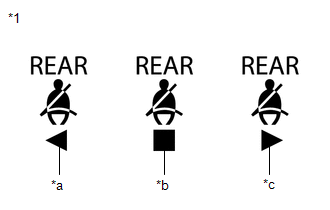
3. INSPECT REAR SEAT BELT WARNING LIGHT
| (a) Check the state of the rear seat belt warning light on the radio and display receiver assembly: (1) Turn the power switch off. (2) Open and then close either rear door. (3) Turn the power switch on (IG). (4) When a rear seat belt is not fastened, check that the rear seat belt warning light on the radio and display receiver assembly is illuminated. (5) After 30 seconds, check that the rear seat belt warning light on the radio and display receiver assembly turns off. (6) When one of the rear seat belts is unfastened from being fastened, check that the rear seat belt warning light on the radio and display receiver assembly illuminates. |
|
4. INSPECT SEAT BELT WARNING BUZZER
HINT:
The seat belt warning buzzer can be customized. Make sure that this function is ON.
Click here
(a) for Front Seat Belt Warning Buzzer:
(1) Place a weight of 20 kg (44.0 lb) on the front passenger seat.
NOTICE:
Place the weight on the seat cushion and allow it to come into contact with the seatback.
(2) After turning the power switch on (IG), wait for approximately 1.8 seconds with the driver seat belt not fastened check that the seat belt warning buzzer in the combination meter assembly sounds at an interval of 1.2 seconds for 6 seconds.
(3) Lift the vehicle using a swing arm type lift.
Click here
(4) Turn the power switch on (READY).
(5) When the driver or front passenger seat belt is not fastened and the vehicle is driven at approximately 20 km/h (12 mph) or more, check that the seat belt warning buzzer in the combination meter assembly sounds once.
(6) When 24 seconds have passed after the buzzer sounded, check that the seat belt warning buzzer in the combination meter assembly sounds at an interval of 1.2 seconds for 6 seconds.
(7) After the seat belt warning buzzer has been sounding for 6 seconds at an interval of 1.2 seconds, check that the seat belt warning buzzer in the combination meter assembly sounds at an interval of 0.4 seconds for 90 seconds.
(8) Check that the seat belt warning buzzer in the combination meter assembly stops 96 seconds after it started sounding at an interval of 1.2 seconds.
(9) After the seat belt warning buzzer in the combination meter assembly stops, turn the power switch off and then start the hybrid control system. Drive the vehicle at approximately 20 km/h (12 mph) or more with either the driver or front passenger seat belt not fastened and check that the buzzer sounds in the same pattern again.
(10) After the seat belt warning buzzer in the combination meter assembly stops, fasten the driver or front passenger seat belt, drive the vehicle at approximately 20 km/h (12 mph) or more, unfasten the driver or front passenger seat belt and check that the buzzer sounds in the same pattern again.
(b) for Rear Seat Belt Warning Buzzer:
(1) Open and close either rear door.
(2) Lift the vehicle using a swing arm type lift.
Click here
(3) Fasten the driver seat belt.
(4) Turn the power switch on (READY).
(5) Fasten and unfasten a rear seat belt then drive the vehicle at approximately 20 km/h (12 mph) or more and check that the seat belt warning buzzer in the combination meter assembly sounds once.
(6) When 24 seconds have passed after the buzzer sounded, check that the seat belt warning buzzer in the combination meter assembly sounds at an interval of 1.2 seconds for 6 seconds.
(7) After the seat belt warning buzzer has been sounding for 6 seconds at an interval of 1.2 seconds, check that the seat belt warning buzzer in the combination meter assembly sounds at an interval of 0.4 seconds for 30 seconds.
(8) Check that the seat belt warning buzzer in the combination meter assembly stops 36 seconds after it started sounding at an interval of 1.2 seconds.
(9) After the seat belt warning buzzer in the combination meter assembly stops, turn the power switch off, open and close either rear door and then start the hybrid control system. Fasten and unfasten a rear seat belt then drive the vehicle at approximately 20 km/h (12 mph) or more and check that the buzzer sounds in the same pattern again.
(10) After the seat belt warning buzzer in the combination meter assembly stops, fasten a rear seat belt, drive the vehicle at approximately 20 km/h (12 mph) or more, unfasten the rear seat belt and check that the buzzer sounds in the same pattern again.
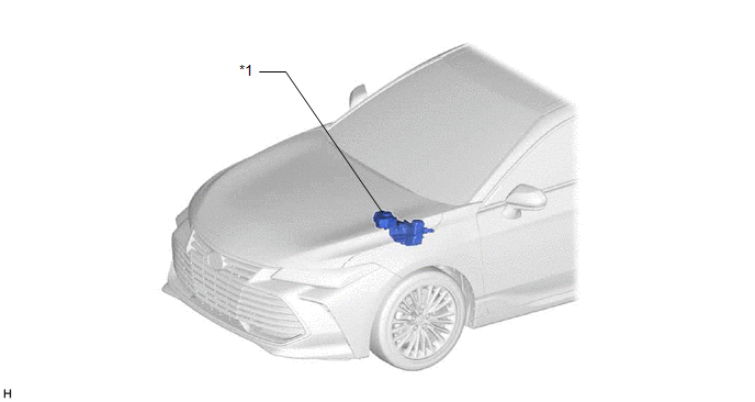
PARTS LOCATION
ILLUSTRATION
|
*1 | BRAKE BOOSTER WITH MASTER CYLINDER ASSEMBLY - SKID CONTROL ECU | - |
- |
ILLUSTRATION
|
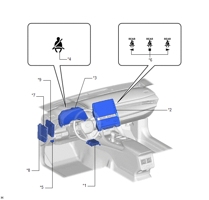
*1 | AIRBAG ECU ASSEMBLY |
*2 | RADIO AND DISPLAY RECEIVER ASSEMBLY |
|
*3 | COMBINATION METER ASSEMBLY - SEAT BELT WARNING BUZZER |
*4 | SEAT BELT WARNING LIGHT |
|
*5 | DLC3 |
*6 | REAR SEAT BELT WARNING LIGHT |
|
*7 | MAIN BODY ECU (MULTIPLEX NETWORK BODY ECU) |
*8 | INSTRUMENT PANEL JUNCTION BLOCK ASSEMBLY - ECU-IG1 NO. 4 FUSE |
|
*9 | HYBRID VEHICLE CONTROL ECU ASSEMBLY |
- | - |
ILLUSTRATION
|
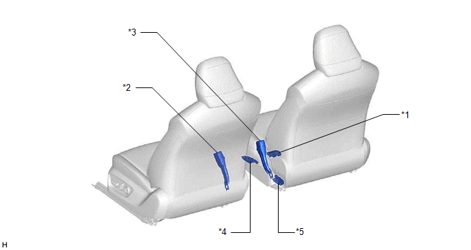
*1 | OCCUPANT DETECTION ECU |
*2 | FRONT SEAT INNER BELT ASSEMBLY LH |
|
*3 | FRONT SEAT INNER BELT ASSEMBLY RH |
*4 | FRONT OCCUPANT CLASSIFICATION SENSOR LH |
|
*5 | REAR OCCUPANT CLASSIFICATION SENSOR LH |
- | - |
ILLUSTRATION
|
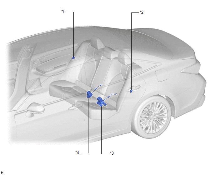
*1 | REAR DOOR COURTESY LIGHT SWITCH ASSEMBLY (RH) |
*2 | REAR DOOR COURTESY LIGHT SWITCH ASSEMBLY (LH) |
|
*3 | REAR SEAT INNER BELT ASSEMBLY LH |
*4 | REAR SEAT INNER WITH CENTER BELT ASSEMBLY RH |
PRECAUTION
PRECAUTION FOR DISCONNECTING CABLE FROM NEGATIVE AUXILIARY BATTERY TERMINAL
NOTICE:
When disconnecting the cable from the negative (-) auxiliary battery terminal, initialize the following systems after the cable is reconnected.
|
System Name | See Procedure |
|---|---|
|
Lane Departure Alert System (w/ Steering Control) |
|
|
Intelligent Clearance Sonar System | |
|
Parking Assist Monitor System | |
|
Panoramic View Monitor System | |
|
Pre-collision System | |
|
Lighting System (for HV Model with Cornering Light) |
PROBLEM SYMPTOMS TABLE
HINT:
|
Symptom | Suspected Area |
Link |
|---|---|---|
| Driver side seat belt warning light does not operate |
Refer to the "Driver Side Seat Belt Warning Light does not Operate'' |
 |
|
Front passenger side seat belt warning light does not operate |
Refer to the "Front Passenger Side Seat Belt Warning Light does not Operate'' |
|
|
Rear seat belt warning light malfunction |
Refer to the "Rear Seat Belt Warning Light Malfunction" |
|
|
Seat belt warning light does not operate for all seats |
Combination meter assembly |
|
|
Seat belt warning buzzer does not operate |
Check customized settings using the Techstream |
|
|
Combination meter assembly |
|
DESCRIPTION
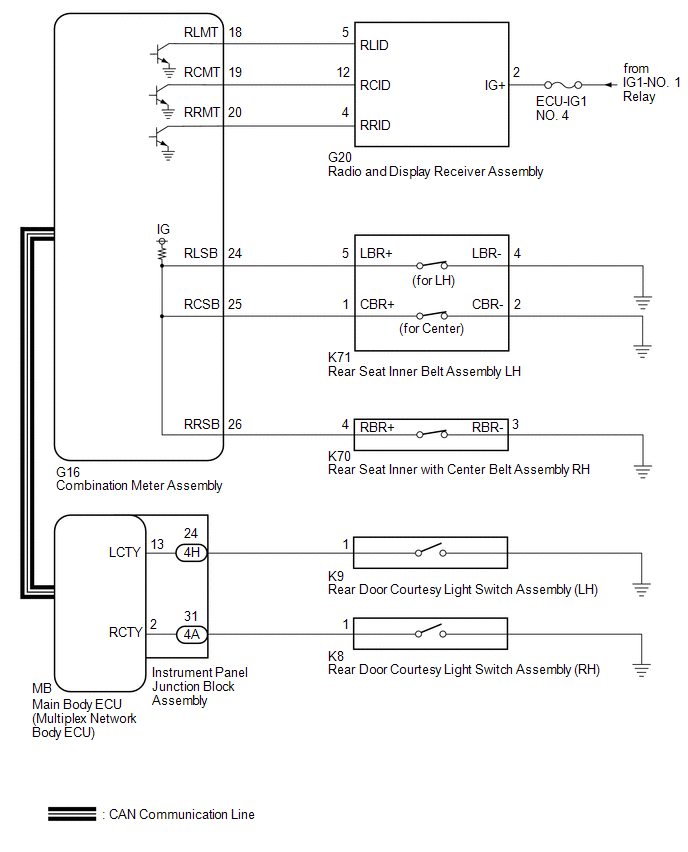
The main body ECU (multiplex network body ECU) detects whether either the rear doors are open or closed based on the courtesy light switch condition and then sends the rear door status signal to the combination meter assembly. The combination meter assembly detects rear seat belt state. The rear seat belt warning light on the radio and display receiver assembly illuminates, blinks or turns off in accordance with the rear door state, vehicle speed and rear seat belt state.
WIRING DIAGRAM
CAUTION / NOTICE / HINT
NOTICE:
Click here 
PROCEDURE
|
1. | READ VALUE USING TECHSTREAM (REAR DOOR COURTESY LIGHT SWITCH) |
(a) Connect the Techstream to the DLC3.
(b) Turn the power switch on (IG).
(c) Turn the Techstream on.
(d) Enter the following menus: Body Electrical / Main Body / Data List.
(e) Read the Data List according to the display on the Techstream.
Body Electrical > Main Body > Data List|
Tester Display | Measurement Item |
Range | Normal Condition |
Diagnostic Note |
|---|---|---|---|---|
|
RR Door Courtesy SW | Rear door courtesy light switch RH |
ON or OFF | ON: Rear door RH open OFF: Rear door RH closed |
- |
| RL Door Courtesy SW |
Rear door courtesy light switch LH |
ON or OFF | ON: Rear door LH open OFF: Rear door LH closed |
- |
|
Tester Display |
|---|
| RR Door Courtesy SW |
|
RL Door Courtesy SW |
OK:
The Techstream display changes correctly in response to the rear door condition.
| NG |  | GO TO LIGHTING SYSTEM |
|
| 2. |
CHECK REAR SEAT BELT WARNING |
| (a) Check the rear seat belt warning function. Click here
|
|
|
Result | Proceed to |
|---|---|
|
The rear seat belt warning lights operation is normal |
A |
| The rear seat belt warning lights (all seats) do not operate normally |
B |
| The rear seat belt warning light (RH) does not operate normally |
C |
| The rear seat belt warning light (center) does not operate normally |
D |
| The rear seat belt warning light (LH) does not operate normally |
E |
| A |
| USE SIMULATION METHOD TO CHECK |
| C |
| GO TO STEP 6 |
| D |
| GO TO STEP 10 |
| E |
| GO TO STEP 14 |
|
| 3. |
PERFORM ACTIVE TEST USING TECHSTREAM (REAR SEAT BELT WARNING LIGHT) |
(a) Connect the Techstream to the DLC3.
(b) Turn the power switch on (IG).
(c) Turn the Techstream on.
(d) Enter the following menus: Body Electrical / Combination Meter / Active Test.
(e) Perform the Active Test according to the display on the Techstream.
Body Electrical > Combination Meter > Active Test|
Tester Display | Measurement Item |
Control Range | Diagnostic Note |
|---|---|---|---|
|
Rear Seat Belt Warning |
Rear seat belt warning light |
OFF/ON | - |
|
Tester Display |
|---|
| Rear Seat Belt Warning |
|
Result | Proceed to |
|---|---|
|
The rear seat belt warning light does not operate normally |
A |
| The rear seat belt warning light operates normally |
B |
| B |
| REPLACE COMBINATION METER ASSEMBLY |
|
| 4. |
CHECK HARNESS AND CONNECTOR (POWER SOURCE - RADIO AND DISPLAY RECEIVER ASSEMBLY) |
(a) Disconnect the G20 radio and display receiver assembly connector.
(b) Measure the voltage according to the value(s) in the table below.
Standard Voltage:
|
Tester Connection | Condition |
Specified Condition |
|---|---|---|
|
G20-2 (IG+) - Body ground |
Power switch on (IG) |
11 to 14 V |
| NG | | REPAIR OR REPLACE HARNESS OR CONNECTOR |
|
| 5. |
CHECK HARNESS AND CONNECTOR (RADIO AND DISPLAY RECEIVER ASSEMBLY - COMBINATION METER ASSEMBLY) |
(a) Reconnect the G20 radio and display receiver assembly connector.
(b) Disconnect the G16 combination meter assembly connector.
(c) Measure the voltage according to the value(s) in the table below.
Standard Voltage:
|
Tester Connection | Condition |
Specified Condition |
|---|---|---|
|
G16-18 (RLMT) - Body ground |
Power switch on (IG) |
11 to 14 V |
|
G16-19 (RCMT) - Body ground |
Power switch on (IG) |
11 to 14 V |
|
G16-20 (RRMT) - Body ground |
Power switch on (IG) |
11 to 14 V |
| OK | | REPLACE COMBINATION METER ASSEMBLY |
| NG | | REPLACE RADIO AND DISPLAY RECEIVER ASSEMBLY |
| 6. |
READ VALUE USING TECHSTREAM (REAR SEAT BELT BUCKLE SWITCH (FOR RH)) |
(a) Connect the Techstream to the DLC3.
(b) Turn the power switch on (IG).
(c) Turn the Techstream on.
(d) Enter the following menus: Body Electrical / Combination Meter / Data List.
(e) Read the Data List according to the display on the Techstream.
Body Electrical > Combination Meter > Data List|
Tester Display | Measurement Item |
Range | Normal Condition |
Diagnostic Note |
|---|---|---|---|---|
|
Rear Right Seat Buckle / Occupant Detection Warning Switch |
Rear seat inner with center belt RH buckle signal |
ON or OFF | OFF: Rear RH seat belt fastened ON: Rear RH seat belt not fastened |
- |
|
Tester Display |
|---|
| Rear Right Seat Buckle / Occupant Detection Warning Switch |
|
Result | Proceed to |
|---|---|
|
ON or OFF does not appear on the Techstream according to the rear seat belt condition |
A |
| ON or OFF appears on the Techstream according to the rear seat belt condition |
B |
| B |
| GO TO STEP 8 |
|
| 7. |
CHECK HARNESS AND CONNECTOR (COMBINATION METER ASSEMBLY - REAR SEAT INNER WITH CENTER BELT ASSEMBLY RH - BODY GROUND) |
(a) Disconnect the G16 combination meter assembly connector.
(b) Disconnect the K70 rear seat inner with center belt assembly RH connector.
(c) Measure the resistance according to the value(s) in the table below.
Standard Resistance:
|
Tester Connection | Condition |
Specified Condition |
|---|---|---|
|
G16-26 (RRSB) - K70-4 (RBR+) |
Always | Below 1 Ω |
|
G16-26 (RRSB) or K70-4 (RBR+) - Body ground |
Always | 10 kΩ or higher |
|
K70-3 (RBR-) - Body ground |
Always | Below 1 Ω |
| OK | | REPLACE REAR SEAT INNER WITH CENTER BELT ASSEMBLY RH |
| NG | | REPAIR OR REPLACE HARNESS OR CONNECTOR |
| 8. |
PERFORM ACTIVE TEST USING TECHSTREAM (REAR SEAT BELT WARNING LIGHT) |
(a) Connect the Techstream to the DLC3.
(b) Turn the power switch on (IG).
(c) Turn the Techstream on.
(d) Enter the following menus: Body Electrical / Combination Meter / Active Test.
(e) Perform the Active Test according to the display on the Techstream.
Body Electrical > Combination Meter > Active Test|
Tester Display | Measurement Item |
Control Range | Diagnostic Note |
|---|---|---|---|
|
Rear Seat Belt Warning |
Rear seat belt warning light |
OFF/ON | - |
|
Tester Display |
|---|
| Rear Seat Belt Warning |
|
Result | Proceed to |
|---|---|
|
The rear seat belt warning light does not operate normally |
A |
| The rear seat belt warning light operates normally |
B |
| B |
| REPLACE COMBINATION METER ASSEMBLY |
|
| 9. |
CHECK HARNESS AND CONNECTOR (RADIO AND DISPLAY RECEIVER ASSEMBLY - COMBINATION METER ASSEMBLY) |
(a) Disconnect the G16 combination meter assembly connector.
(b) Disconnect the G20 radio and display receiver assembly connector.
(c) Measure the resistance according to the value(s) in the table below.
Standard Resistance:
|
Tester Connection | Condition |
Specified Condition |
|---|---|---|
|
G16-20 (RRMT) - G20-4 (RRID) |
Always | Below 1 Ω |
|
G16-20 (RRMT) or G20-4 (RRID) - Body ground |
Always | 10 kΩ or higher |
| OK | | REPLACE RADIO AND DISPLAY RECEIVER ASSEMBLY |
| NG | | REPAIR OR REPLACE HARNESS OR CONNECTOR |
| 10. |
READ VALUE USING TECHSTREAM (REAR SEAT BELT BUCKLE SWITCH (FOR CENTER)) |
(a) Connect the Techstream to the DLC3.
(b) Turn the power switch on (IG).
(c) Turn the Techstream on.
(d) Enter the following menus: Body Electrical / Combination Meter / Data List.
(e) Read the Data List according to the display on the Techstream.
Body Electrical > Combination Meter > Data List|
Tester Display | Measurement Item |
Range | Normal Condition |
Diagnostic Note |
|---|---|---|---|---|
|
Rear Center Seat Buckle / Occupant Detection Warning Switch |
Rear seat inner belt LH (for center) buckle signal |
ON or OFF | OFF: Rear LH seat belt (for center) fastened ON: Rear LH seat belt (for center) not fastened |
- |
|
Tester Display |
|---|
| Rear Center Seat Buckle / Occupant Detection Warning Switch |
|
Result | Proceed to |
|---|---|
|
ON or OFF does not appear on the Techstream according to the rear seat belt condition |
A |
| ON or OFF appears on the Techstream according to the rear seat belt condition |
B |
| B |
| GO TO STEP 12 |
|
| 11. |
CHECK HARNESS AND CONNECTOR (COMBINATION METER ASSEMBLY - REAR SEAT INNER BELT ASSEMBLY LH - BODY GROUND) |
(a) Disconnect the G16 combination meter assembly connector.
(b) Disconnect the K71 rear seat inner belt assembly LH connector.
(c) Measure the resistance according to the value(s) in the table below.
Standard Resistance:
|
Tester Connection | Condition |
Specified Condition |
|---|---|---|
|
G16-25 (RCSB) - K71-1 (CBR+) |
Always | Below 1 Ω |
|
G16-25 (RCSB) or K71-1 (CBR+) - Body ground |
Always | 10 kΩ or higher |
|
K71-2 (CBR-) - Body ground |
Always | Below 1 Ω |
| OK | | REPLACE REAR SEAT INNER BELT ASSEMBLY LH |
| NG | | REPAIR OR REPLACE HARNESS OR CONNECTOR |
| 12. |
PERFORM ACTIVE TEST USING TECHSTREAM (REAR SEAT BELT WARNING LIGHT) |
(a) Connect the Techstream to the DLC3.
(b) Turn the power switch on (IG).
(c) Turn the Techstream on.
(d) Enter the following menus: Body Electrical / Combination Meter / Active Test.
(e) Perform the Active Test according to the display on the Techstream.
Body Electrical > Combination Meter > Active Test|
Tester Display | Measurement Item |
Control Range | Diagnostic Note |
|---|---|---|---|
|
Rear Seat Belt Warning |
Rear seat belt warning light |
OFF/ON | - |
|
Tester Display |
|---|
| Rear Seat Belt Warning |
|
Result | Proceed to |
|---|---|
|
The rear seat belt warning light does not operate normally |
A |
| The rear seat belt warning light operates normally |
B |
| B |
| REPLACE COMBINATION METER ASSEMBLY |
|
| 13. |
CHECK HARNESS AND CONNECTOR (RADIO AND DISPLAY RECEIVER ASSEMBLY - COMBINATION METER ASSEMBLY) |
(a) Disconnect the G16 combination meter assembly connector.
(b) Disconnect the G20 radio and display receiver assembly connector.
(c) Measure the resistance according to the value(s) in the table below.
Standard Resistance:
|
Tester Connection | Condition |
Specified Condition |
|---|---|---|
|
G16-19 (RCMT) - G20-12 (RCID) |
Always | Below 1 Ω |
|
G16-19 (RCMT) or G20-12 (RCID) - Body ground |
Always | 10 kΩ or higher |
| OK | | REPLACE RADIO AND DISPLAY RECEIVER ASSEMBLY |
| NG | | REPAIR OR REPLACE HARNESS OR CONNECTOR |
| 14. |
READ VALUE USING TECHSTREAM (REAR SEAT BELT BUCKLE SWITCH (FOR LH)) |
(a) Connect the Techstream to the DLC3.
(b) Turn the power switch on (IG).
(c) Turn the Techstream on.
(d) Enter the following menus: Body Electrical / Combination Meter / Data List.
(e) Read the Data List according to the display on the Techstream.
Body Electrical > Combination Meter > Data List|
Tester Display | Measurement Item |
Range | Normal Condition |
Diagnostic Note |
|---|---|---|---|---|
|
Rear Left Seat Buckle / Occupant Detection Warning Switch |
Rear seat inner belt LH (for LH) buckle signal |
ON or OFF | OFF: Rear LH seat belt (for LH) fastened ON: Rear LH seat belt (for LH) not fastened |
- |
|
Tester Display |
|---|
| Rear Left Seat Buckle / Occupant Detection Warning Switch |
|
Result | Proceed to |
|---|---|
|
ON or OFF does not appear on the Techstream according to the rear seat belt condition |
A |
| ON or OFF appears on the Techstream according to the rear seat belt condition |
B |
| B |
| GO TO STEP 16 |
|
| 15. |
CHECK HARNESS AND CONNECTOR (COMBINATION METER ASSEMBLY - REAR SEAT INNER BELT ASSEMBLY LH - BODY GROUND) |
(a) Disconnect the G16 combination meter assembly connector.
(b) Disconnect the K71 rear seat inner belt assembly LH connector.
(c) Measure the resistance according to the value(s) in the table below.
Standard Resistance:
|
Tester Connection | Condition |
Specified Condition |
|---|---|---|
|
G16-24 (RLSB) - K71-5 (LBR+) |
Always | Below 1 Ω |
|
G16-24 (RLSB) or K71-5 (LBR+) - Body ground |
Always | 10 kΩ or higher |
|
K71-4 (LBR-) - Body ground |
Always | Below 1 Ω |
| OK | | REPLACE REAR SEAT INNER BELT ASSEMBLY LH |
| NG | | REPAIR OR REPLACE HARNESS OR CONNECTOR |
| 16. |
PERFORM ACTIVE TEST USING TECHSTREAM (REAR SEAT BELT WARNING LIGHT) |
(a) Connect the Techstream to the DLC3.
(b) Turn the power switch on (IG).
(c) Turn the Techstream on.
(d) Enter the following menus: Body Electrical / Combination Meter / Active Test.
(e) Perform the Active Test according to the display on the Techstream.
Body Electrical > Combination Meter > Active Test|
Tester Display | Measurement Item |
Control Range | Diagnostic Note |
|---|---|---|---|
|
Rear Seat Belt Warning |
Rear seat belt warning light |
OFF/ON | - |
|
Tester Display |
|---|
| Rear Seat Belt Warning |
|
Result | Proceed to |
|---|---|
|
The rear seat belt warning light does not operate normally |
A |
| The rear seat belt warning light operates normally |
B |
| B |
| REPLACE COMBINATION METER ASSEMBLY |
|
| 17. |
CHECK HARNESS AND CONNECTOR (RADIO AND DISPLAY RECEIVER ASSEMBLY - COMBINATION METER ASSEMBLY) |
(a) Disconnect the G16 combination meter assembly connector.
(b) Disconnect the G20 radio and display receiver assembly connector.
(c) Measure the resistance according to the value(s) in the table below.
Standard Resistance:
|
Tester Connection | Condition |
Specified Condition |
|---|---|---|
|
G16-18 (RLMT) - G20-5 (RLID) |
Always | Below 1 Ω |
|
G16-18 (RLMT) or G20-5 (RLID) - Body ground |
Always | 10 kΩ or higher |
| OK | | REPLACE RADIO AND DISPLAY RECEIVER ASSEMBLY |
| NG | | REPAIR OR REPLACE HARNESS OR CONNECTOR |
SYSTEM DESCRIPTION
SEAT BELT WARNING SYSTEM DESCRIPTION
(a) Seat belt warning light operation for driver seat belt:
The seat belt warning light on the combination meter assembly illuminates, blinks or turns off in accordance with the driver seat belt state, vehicle speed, shift lever position and parking brake state.
(b) Seat belt warning light operation for front passenger seat belt:
The seat belt warning light on the combination meter assembly illuminates, blinks or turns off in accordance with whether the front passenger seat is occupied, the front passenger seat belt state, vehicle speed, shift lever position and parking brake state.
(c) Rear seat belt warning light:
The rear seat belt warning light on the radio and display receiver assembly illuminates, blinks or turns off in accordance with the rear door state, vehicle speed and rear seat belt state.
(d) Front seat belt warning buzzer:
After turning the power switch on (IG), if the driver seat belt is not fastened within 1.8 seconds, the seat belt warning buzzer in the combination meter assembly will sound at an interval of 1.2 seconds for 6 seconds.
When the vehicle is driven at approximately 20 km/h (12 mph) or more with the front passenger seat occupied and the driver or front passenger seat belt not fastened, the seat belt warning buzzer in the combination meter assembly will sound once.
When 24 seconds have passed after the buzzer sounded, the seat belt warning buzzer in the combination meter assembly will sound at an interval of 1.2 seconds for 6 seconds.
After that, the seat belt warning buzzer in the combination meter assembly will sound at an interval of 0.4 seconds for 90 seconds.
(e) Rear seat belt warning buzzer:
When the vehicle is driven at approximately 20 km/h (12 mph) or more with a rear seat belt not fastened, the seat belt warning buzzer in the combination meter assembly will sound at an interval of 1.2 seconds for 6 seconds.
After that, the seat belt warning buzzer in the combination meter assembly will sound at an interval of 0.4 seconds for 30 seconds.
FUNCTION OF MAIN COMPONENTS
|
Component | Function |
|---|---|
|
Front seat inner belt assembly LH | Informs the airbag ECU assembly of the driver seat belt condition (fastened or unfastened). |
|
Front seat inner belt assembly RH | Informs the occupant detection ECU of the front passenger seat belt condition (fastened or unfastened). |
| Informs the occupant detection ECU of the front passenger seat condition (occupied or unoccupied). |
|
Combination meter assembly |
|
| Occupant detection ECU |
Sends the front passenger seat belt buckle switch signal and occupant detection signal to the airbag ECU assembly via CAN communication. |
|
Airbag ECU assembly |
|
| Radio and display receiver assembly |
Illuminates, blinks or turns off the rear seat belt warning light. |
| Informs the combination meter assembly of each rear seat belt condition (fastened or unfastened). |
|
Rear door courtesy light switch assembly (LH/RH) |
Informs the main body ECU (multiplex network body ECU) of the rear door condition (open or closed). |
|
Main body ECU (multiplex network body ECU) | Sends the driver seat belt buckle switch signal, parking brake signal and rear door courtesy light switch signal to the combination meter assembly via CAN communication. |
| Skid control ECU (brake booster with master cylinder assembly) |
Sends the vehicle speed signal to the combination meter assembly via CAN communication. |
|
Hybrid vehicle control ECU assembly |
Sends the shift position signal to the combination meter assembly via CAN communication. |
SYSTEM DIAGRAM
FRONT SEAT BELT WARNING
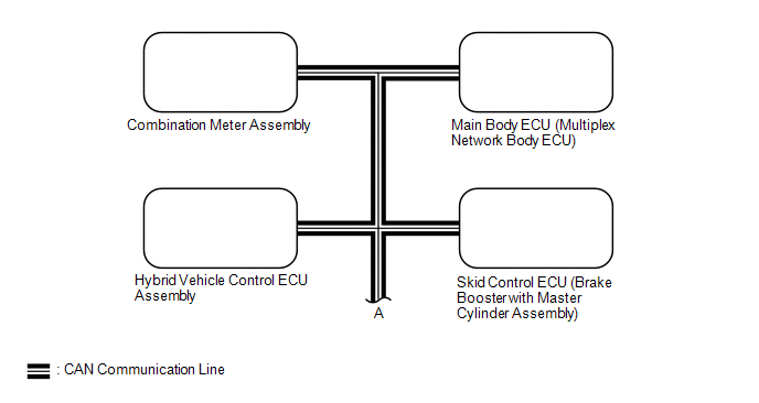
 Communication Table
 |
Sender | Receiver |
Signal | Communication Method |
|---|---|---|---|
|
Airbag ECU assembly | Main body ECU (multiplex network body ECU) |
Front seat inner belt assembly LH buckle switch |
CAN |
| Combination meter assembly |
| ||
| Skid control ECU (brake booster with master cylinder assembly) |
Combination meter assembly | Vehicle speed | |
|
Hybrid vehicle control ECU assembly |
Combination meter assembly | Shift position | |
|
Occupant detection ECU | Airbag ECU assembly |
| |
| Main body ECU (multiplex network body ECU) |
Combination meter assembly |
|
REAR SEAT BELT WARNING
 Communication Table
 |
Sender | Receiver |
Signal | Communication Method |
|---|---|---|---|
|
Main body ECU (multiplex network body ECU) |
Combination meter assembly |
| CAN |
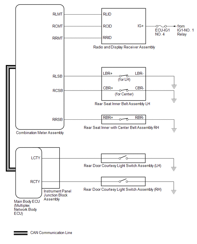
TERMINALS OF ECU
CHECK MAIN BODY ECU (MULTIPLEX NETWORK BODY ECU) AND INSTRUMENT PANEL JUNCTION BLOCK ASSEMBLY
(a) Disconnect the instrument panel junction block assembly and main body ECU (multiplex network body ECU) connectors.
Click here 
(b) Reconnect the instrument panel junction block assembly connectors.
(c) Measure the resistance and voltage according to the value(s) in the table below.
HINT:
Measure the values on the wire harness side with the connector disconnected.
|
Terminal No. (Symbol) | Wiring Color |
Terminal Description | Condition |
Specified Condition |
|---|---|---|---|---|
|
MB-31 (BECU) - Body ground |
- | Auxiliary battery power supply |
Power switch off | 11 to 14 V |
|
MB-32 (IG) - Body ground |
- | Ignition power supply (IG signal) |
Power switch on (IG) |
11 to 14 V |
|
Power switch off | Below 1 V | |||
|
MB-30 (ACC) - Body ground |
- | Ignition power supply (ACC signal) |
Power switch on (ACC) |
11 to 14 V |
|
Power switch off | Below 1 V | |||
|
MB-11 (GND1) - Body ground |
- | Ground |
Always | Below 1 Ω |
|
MB-2 (RCTY) - Body ground |
- | Rear door courtesy light switch RH input |
Rear door RH closed (OFF) |
10 kΩ or higher |
|
Rear door RH open (ON) |
Below 1 Ω | |||
|
MB-13 (LCTY) - Body ground |
- | Rear door courtesy light switch LH input |
Rear door LH closed (OFF) |
10 kΩ or higher |
|
Rear door LH open (ON) |
Below 1 Ω |
CHECK COMBINATION METER ASSEMBLY
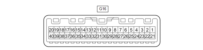
(a) Disconnect the G16 combination meter assembly connector.
(b) Measure the resistance and voltage according to the value(s) in the table below.
HINT:
Measure the values on the wire harness side with the connector disconnected.
|
Terminal No. (Symbol) | Wiring Color |
Terminal Description | Condition |
Specified Condition |
|---|---|---|---|---|
|
G16-40 (B) - Body ground |
LA-B - Body ground | Auxiliary battery power supply |
Power switch off | 11 to 14 V |
|
G16-39 (IG+) - Body ground |
GR - Body ground |
Ignition power supply |
Power switch off | Below 1 V |
|
Power switch on (IG) |
11 to 14 V | |||
|
G16-21 (ES) - Body ground |
W-B - Body ground | Ground |
Always | Below 1 Ω |
|
G16-24 (RLSB) - Body ground |
SB - Body ground |
Rear LH seat belt buckle switch signal |
Rear LH seat belt fastened |
10 kΩ or higher |
|
Rear LH seat belt unfastened |
Below 1 Ω | |||
|
G16-26 (RRSB) - Body ground |
LG - Body ground |
Rear RH seat belt buckle switch signal |
Rear RH seat belt fastened |
10 kΩ or higher |
|
Rear RH seat belt unfastened |
Below 1 Ω | |||
|
G16-25 (RCSB) - Body ground |
B - Body ground |
Rear center seat belt buckle switch signal |
Rear center seat belt fastened |
10 kΩ or higher |
|
Rear center seat belt unfastened |
Below 1 Ω |
(c) Reconnect the G16 combination meter assembly connector.
(d) Measure the voltage according to the value(s) in the table below.
|
Terminal No. (Symbol) | Wiring Color |
Terminal Description | Condition |
Specified Condition |
|---|---|---|---|---|
|
G16-18 (RLMT) - Body ground |
BE - Body ground |
Rear LH seat belt warning light output signal |
Power switch on (IG), rear seat belt warning light (LH) off |
11 to 14 V |
|
Power switch on (IG), rear seat belt warning light (LH) on |
Below 1 V | |||
|
G16-20 (RRMT) - Body ground |
G - Body ground |
Rear center seat belt warning light output signal |
Power switch on (IG), rear seat belt warning light (center) off |
11 to 14 V |
|
Power switch on (IG), rear seat belt warning light (center) on |
Below 1 V | |||
|
G16-19 (RCMT) - Body ground |
R - Body ground |
Rear RH seat belt warning light output signal |
Power switch on (IG), rear seat belt warning light (RH) off |
11 to 14 V |
|
Power switch on (IG), rear seat belt warning light (RH) on |
Below 1 V |
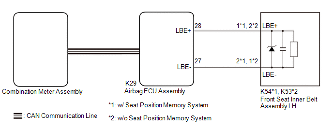
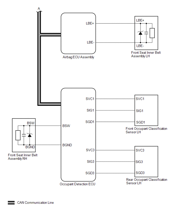
AIRBAG ECU ASSEMBLY
|
Terminal No. | Terminal Symbol |
Destination |
|---|---|---|
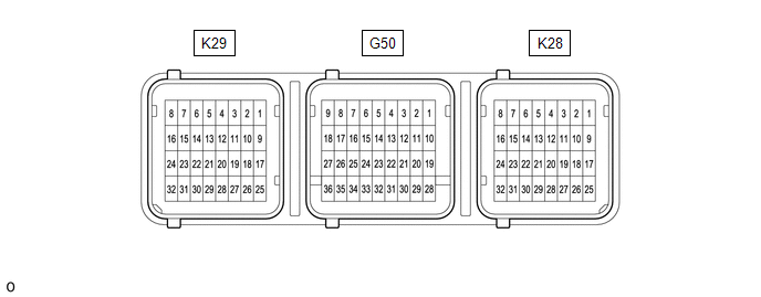
| K29-28 |
LBE+ | Front seat inner belt assembly LH |
|
K29-27 | LBE- |
Front seat inner belt assembly LH |
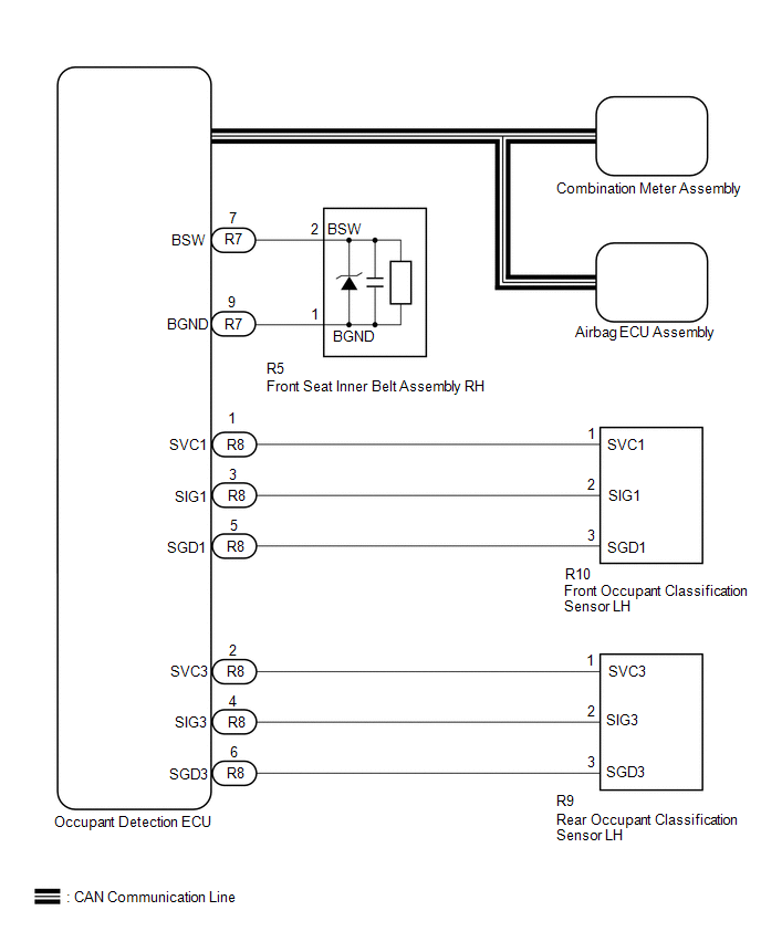
CHECK OCCUPANT DETECTION ECU

(a) Measure the voltage and check for pulses according to the value(s) in the table below.
|
Terminal No. (Symbol) | Wiring Color |
Terminal Description | Condition |
Specified Condition |
|---|---|---|---|---|
|
R7-10 (GND) - Body ground |
W-B - Body ground | Ground |
Always | Below 1 V |
|
R7-6 (IG) - R7-10 (GND) |
B - W-B | Power source |
Power switch on (IG) |
11 to 14 V |
|
R7-9 (BGND) - R7-10 (GND) |
P - W-B | Front passenger buckle switch ground |
Always | Below 1 V |
|
R7-7 (BSW) - R7-9 (BGND) |
G - P | Front passenger buckle switch signal |
Always | Pulse generation |
|
R8-1 (SVC1) - R8-5 (SGD1) |
R - G | Front occupant classification sensor LH power supply |
Power switch on (IG) |
11 to 14 V |
|
R8-2 (SVC3) - R8-6 (SGD3) |
GR - W | Rear occupant classification sensor LH power supply |
Power switch on (IG) |
11 to 14 V |
|
R8-3 (SIG1) - R8-5 (SGD1) |
P - G | Front occupant classification sensor LH signal |
Power switch on (IG) |
Pulse generation |
|
R8-4 (SIG3) - R8-6 (SGD3) |
Y - W | Rear occupant classification sensor LH signal |
Power switch on (IG) |
Pulse generation |
|
R8-5 (SGD1) - R7-10 (GND) |
G - W-B | Front occupant classification sensor LH ground |
Always | Below 1 V |
|
R8-6 (SGD3) - R7-10 (GND) |
W - W-B | Rear occupant classification sensor LH ground |
Always | Below 1 V |
Toyota Avalon (XX50) 2019-2022 Service & Repair Manual > Seat: Power Seat Switch
Components COMPONENTS ILLUSTRATION *1 FRONT SEAT CUSHION SHIELD *2 FRONT SEAT FRONT CUSHION SHIELD ILLUSTRATION *1 FRONT POWER SEAT SWITCH *2 FRONT SEAT CUSHION SHIELD *3 RECLINING POWER SEAT SWITCH KNOB *4 SLIDE AND VERTICAL POWER SEAT SWITCH KNOB Inspection INSPECTION PROCEDURE 1. INSPECT FRONT PO ...