DESCRIPTION
When the power switch is on and the climate control switch (radio and display receiver assembly) is operated, the air conditioning amplifier assembly receives climate control switch position signals and then sends airflow amount signals to each seat cushion climate control blower.
WIRING DIAGRAM
CAUTION / NOTICE / HINT
NOTICE:
Click here 
PROCEDURE
|
1. | CHECK DTC OUTPUT |
(a) Clear DTCs.
Body Electrical > Air Conditioner > Clear DTCs(b) Check for DTCs.
Body Electrical > Air Conditioner > Trouble Codes|
Result | Proceed to |
|---|---|
|
DTC B14B5 is not output |
A |
| DTC B14B5 output |
B |
| B |
 | GO TO SEAT HEATER SYSTEM |
|
| 2. |
CHECK CLIMATE CONTROL SEAT OPERATION |
(a) Check the climate control seat operation.
Click here
|
Result | Proceed to |
|---|---|
|
Climate control seat does not operate (for LH) |
A |
| Climate control seat does not operate (for RH) |
B |
| Both climate control seats do not operate |
C |
| B |
| GO TO STEP 12 |
| C |
| GO TO STEP 21 |
|
| 3. |
PERFORM ACTIVE TEST USING TECHSTREAM |
(a) Connect the Techstream to the DLC3.
(b) Turn the power switch on (IG).
(c) Turn the Techstream on.
(d) Enter the following menus: Body Electrical / Air Conditioner / Active Test.
(e) Perform the Active Test according to the display on the Techstream.
Body Electrical > Air Conditioner > Active Test|
Tester Display | Measurement Item |
Control Range | Diagnostic Note |
|---|---|---|---|
|
Front Left Seat Blower |
Front LH seat blower operation |
OFF or ON | - |
|
Tester Display |
|---|
| Front Left Seat Blower |
OK:
The seat blower operates normally.
|
Result | Proceed to |
|---|---|
|
Only seatback climate control blower LH does not operate |
A |
| Only seat cushion climate control blower LH does not operate |
B |
| Both seat blowers do not operate |
C |
| B |
| REPLACE SEAT CUSHION CLIMATE CONTROL BLOWER LH |
| C |
| GO TO STEP 7 |
|
| 4. |
CHECK HARNESS AND CONNECTOR (SEAT CUSHION CLIMATE CONTROL BLOWER LH - SEATBACK CLIMATE CONTROL BLOWER LH) |
(a) Disconnect the a11 seatback climate control blower LH connector.
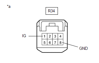
(b) Disconnect the R34 seat cushion climate control blower LH connector.
(c) Measure the resistance according to the value(s) in the table below.
Standard Resistance:
|
Tester Connection | Condition |
Specified Condition |
|---|---|---|
|
a11-1 (CTB) - R34-5 (CTB) |
Always | Below 1 Ω |
|
a11-1 (CTB) or R34-5 (CTB) - Body ground |
Always | 10 kΩ or higher |
|
a11-3 (BBS) - R34-6 (BBS) |
Always | Below 1 Ω |
|
a11-3 (BBS) or R34-6 (BBS) - Body ground |
Always | 10 kΩ or higher |
|
a11-4 (BFB-) - R34-4 (BFB-) |
Always | Below 1 Ω |
|
a11-4 (BFB-) or R34-4 (BFB-) - Body ground |
Always | 10 kΩ or higher |
| NG | | REPAIR OR REPLACE HARNESS OR CONNECTOR |
|
| 5. |
REPLACE SEATBACK CLIMATE CONTROL BLOWER LH |
(a) Temporarily replace the seatback climate control blower LH with a new or known good one.
Click here
|
| 6. |
CHECK CLIMATE CONTROL SEAT OPERATION |
(a) Check the climate control seat operation.
Click here
OK:
The climate control seat operates normally.
| OK | | END (SEATBACK CLIMATE CONTROL BLOWER LH WAS DEFECTIVE) |
| NG | | REPLACE SEAT CUSHION CLIMATE CONTROL BLOWER LH |
| 7. |
CHECK HARNESS AND CONNECTOR (IG POWER SUPPLY - SEAT CUSHION CLIMATE CONTROL BLOWER LH - BODY GROUND) |
| (a) Disconnect the R34 seat cushion climate control blower LH connector. |
|
(b) Measure the voltage and resistance according to the value(s) in the table below.
Standard Voltage:
|
Tester Connection | Condition |
Specified Condition |
|---|---|---|
|
R34-1 (IG) - Body ground |
Power switch on (IG) |
11 to 14 V |
|
R34-1 (IG) - Body ground |
Power switch off | Below 1 V |
Standard Resistance:
|
Tester Connection | Condition |
Specified Condition |
|---|---|---|
|
R34-8 (GND) - Body ground |
Always | Below 1 Ω |
| NG | | REPAIR OR REPLACE HARNESS OR CONNECTOR |
|
| 8. |
CHECK HARNESS AND CONNECTOR (SEAT CUSHION CLIMATE CONTROL BLOWER LH - AIR CONDITIONING AMPLIFIER ASSEMBLY) |
(a) Disconnect the G35 air conditioning amplifier assembly connector.
(b) Measure the resistance according to the value(s) in the table below.
Standard Resistance:
|
Tester Connection | Condition |
Specified Condition |
|---|---|---|
|
R34-7 (SIGN) - G35-24 (LOUT) |
Always | Below 1 Ω |
|
R34-7 (SIGN) or G35-24 (LOUT) - Body ground |
Always | 10 kΩ or higher |
| NG | | REPAIR OR REPLACE HARNESS OR CONNECTOR |
|
| 9. |
CHECK AIR CONDITIONING AMPLIFIER ASSEMBLY |
(a) Reconnect the G35 air conditioning amplifier assembly connector.
| (b) Reconnect the R34 seat cushion climate control blower LH connector. |
|
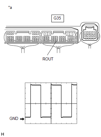
(c) Using an oscilloscope, check the input signal waveform.
Measurement Condition|
Item | Content |
|---|---|
|
Tester Connection | G35-24 (LOUT) - Body ground |
|
Tool Setting | 1 V/DIV., 0.5 ms/DIV. |
|
Vehicle Condition |
|
OK:
Waveform is similar to that shown in the illustration.
| OK | | REPLACE SEAT CUSHION CLIMATE CONTROL BLOWER LH |
|
| 10. |
REPLACE CLIMATE CONTROL SWITCH (RADIO AND DISPLAY RECEIVER ASSEMBLY) |
(a) Temporarily replace the climate control switch (radio and display receiver assembly) with a new or known good one.
Click here
|
| 11. |
CHECK CLIMATE CONTROL SEAT OPERATION |
(a) Check the climate control seat operation.
Click here
OK:
The climate control seat operates normally.
| OK | | END (CLIMATE CONTROL SWITCH (RADIO AND DISPLAY RECEIVER ASSEMBLY) WAS DEFECTIVE) |
| NG | | REPLACE AIR CONDITIONING AMPLIFIER ASSEMBLY |
| 12. |
PERFORM ACTIVE TEST USING TECHSTREAM |
(a) Connect the Techstream to the DLC3.
(b) Turn the power switch on (IG).
(c) Turn the Techstream on.
(d) Enter the following menus: Body Electrical / Air Conditioner / Active Test.
(e) Perform the Active Test according to the display on the Techstream.
Body Electrical > Air Conditioner > Active Test|
Tester Display | Measurement Item |
Control Range | Diagnostic Note |
|---|---|---|---|
|
Front Right Seat Blower |
Front RH seat blower operation |
OFF or ON | - |
|
Tester Display |
|---|
| Front Right Seat Blower |
OK:
The seat blower operates normally.
|
Result | Proceed to |
|---|---|
|
Only seatback climate control blower RH does not operate |
A |
| Only seat cushion climate control blower RH does not operate |
B |
| Both seat blowers do not operate |
C |
| B |
| REPLACE SEAT CUSHION CLIMATE CONTROL BLOWER RH |
| C |
| GO TO STEP 16 |
|
| 13. |
CHECK HARNESS AND CONNECTOR (SEAT CUSHION CLIMATE CONTROL BLOWER RH - SEATBACK CLIMATE CONTROL BLOWER RH) |
(a) Disconnect the a5 seatback climate control blower RH connector.
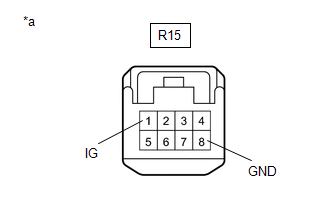
(b) Disconnect the R15 seat cushion climate control blower RH connector.
(c) Measure the resistance according to the value(s) in the table below.
Standard Resistance:
|
Tester Connection | Condition |
Specified Condition |
|---|---|---|
|
R15-5 (CTB) - a5-1 (CTB) |
Always | Below 1 Ω |
|
R15-5 (CTB) or a5-1 (CTB) - Body ground |
Always | 10 kΩ or higher |
|
R15-6 (BBS) - a5-3 (BBS) |
Always | Below 1 Ω |
|
R15-6 (BBS) or a5-3 (BBS) - Body ground |
Always | 10 kΩ or higher |
|
a5-4 (BFB-) - R15-4 (BFB-) |
Always | Below 1 Ω |
|
a5-4 (BFB-) or R15-4 (BFB-) - Body ground |
Always | 10 kΩ or higher |
| NG | | REPAIR OR REPLACE HARNESS OR CONNECTOR |
|
| 14. |
REPLACE SEATBACK CLIMATE CONTROL BLOWER RH |
(a) Temporarily replace the seatback climate control blower RH with a new or known good one.
Click here
|
| 15. |
CHECK CLIMATE CONTROL SEAT OPERATION |
(a) Check the climate control seat operation.
Click here
OK:
The climate control seat operates normally.
| OK | | END (SEATBACK CLIMATE CONTROL BLOWER RH WAS DEFECTIVE) |
| NG | | REPLACE SEAT CUSHION CLIMATE CONTROL BLOWER RH |
| 16. |
CHECK HARNESS AND CONNECTOR (IG POWER SUPPLY - SEAT CUSHION CLIMATE CONTROL BLOWER RH - BODY GROUND) |
| (a) Disconnect the R15 seat cushion climate control blower RH connector. |
|
(b) Measure the voltage and resistance according to the value(s) in the table below.
Standard Voltage:
|
Tester Connection | Condition |
Specified Condition |
|---|---|---|
|
R15-1 (IG) - Body ground |
Power switch on (IG) |
11 to 14 V |
|
R15-1 (IG) - Body ground |
Power switch off | Below 1 V |
Standard Resistance:
|
Tester Connection | Condition |
Specified Condition |
|---|---|---|
|
R15-8 (GND) - Body ground |
Always | Below 1 Ω |
| NG | | REPAIR OR REPLACE HARNESS OR CONNECTOR |
|
| 17. |
CHECK HARNESS AND CONNECTOR (SEAT CUSHION CLIMATE CONTROL BLOWER RH - AIR CONDITIONING AMPLIFIER ASSEMBLY) |
(a) Disconnect the G35 air conditioning amplifier assembly connector.
(b) Measure the resistance according to the value(s) in the table below.
Standard Resistance:
|
Tester Connection | Condition |
Specified Condition |
|---|---|---|
|
R15-7 (SIGN) - G35-23 (ROUT) |
Always | Below 1 Ω |
|
R15-7 (SIGN) or G35-23 (ROUT) - Body ground |
Always | 10 kΩ or higher |
| NG | | REPAIR OR REPLACE HARNESS OR CONNECTOR |
|
| 18. |
CHECK AIR CONDITIONING AMPLIFIER ASSEMBLY |
(a) Reconnect the G35 air conditioning amplifier assembly connector.
| (b) Reconnect the R15 seat cushion climate control blower RH connector. |
|
(c) Using an oscilloscope, check the input signal waveform.
Measurement Condition|
Item | Content |
|---|---|
|
Tester Connection | G35-23 (ROUT) - Body ground |
|
Tool Setting | 1 V/DIV., 0.5 ms/DIV. |
|
Vehicle Condition |
|
OK:
Waveform is similar to that shown in the illustration.
| OK | | REPLACE SEAT CUSHION CLIMATE CONTROL BLOWER RH |
|
| 19. |
REPLACE CLIMATE CONTROL SWITCH (RADIO AND DISPLAY RECEIVER ASSEMBLY) |
(a) Temporarily replace the climate control switch (radio and display receiver assembly) with a new or known good one.
Click here
|
| 20. |
CHECK CLIMATE CONTROL SEAT OPERATION |
(a) Check the climate control seat operation.
Click here
OK:
The climate control seat operates normally.
| OK | | END (CLIMATE CONTROL SWITCH (RADIO AND DISPLAY RECEIVER ASSEMBLY) WAS DEFECTIVE) |
| NG | | REPLACE AIR CONDITIONING AMPLIFIER ASSEMBLY |
| 21. |
CHECK HARNESS AND CONNECTOR (IG POWER SUPPLY - CLIMATE CONTROL SWITCH (RADIO AND DISPLAY RECEIVER ASSEMBLY) - BODY GROUND) |
(a) Disconnect the G20 climate control switch (radio and display receiver assembly) connector.
(b) Measure the voltage and resistance according to the value(s) in the table below.
Standard Voltage:
|
Tester Connection | Condition |
Specified Condition |
|---|---|---|
|
G20-2 (IG+) - Body ground |
Power switch on (IG) |
11 to 14 V |
|
G20-2 (IG+) - Body ground |
Power switch off | Below 1 V |
Standard Resistance:
|
Tester Connection | Condition |
Specified Condition |
|---|---|---|
|
G20-6 (GND) - Body ground |
Always | Below 1 Ω |
| NG | | REPAIR OR REPLACE HARNESS OR CONNECTOR |
|
| 22. |
REPLACE CLIMATE CONTROL SWITCH (RADIO AND DISPLAY RECEIVER ASSEMBLY) |
(a) Temporarily replace the climate control switch (radio and display receiver assembly) with a new or known good one.
Click here
|
| 23. |
CHECK CLIMATE CONTROL SEAT OPERATION |
(a) Check the climate control seat operation.
Click here
OK:
The climate control seat operates normally.
| OK | | END (CLIMATE CONTROL SWITCH (RADIO AND DISPLAY RECEIVER ASSEMBLY) WAS DEFECTIVE) |
| NG | | REPLACE AIR CONDITIONING AMPLIFIER ASSEMBLY |
DATA LIST / ACTIVE TEST
HINT:
Using the Techstream to perform Active Tests allows relays, VSVs, actuators and other items to be operated without removing any parts. This non-intrusive functional inspection can be very useful because intermittent operation may be discovered before parts or wiring is disturbed. Performing Active Tests early in troubleshooting is one way to save diagnostic time. Data List information can be displayed while performing Active Tests.
ACTIVE TEST
(a) Connect the Techstream to the DLC3.
(b) Turn the power switch on (IG).
(c) Turn the Techstream on.
(d) Enter the following menus: Body Electrical / Air Conditioner / Active Test.
(e) Perform the Active Test according to the display on the Techstream.
Body Electrical > Air Conditioner > Active Test|
Tester Display | Measurement Item |
Control Range | Diagnostic Note |
|---|---|---|---|
|
Front Right Seat Blower |
Front RH seat blower operation |
OFF or ON | - |
|
Front Left Seat Blower |
Front LH seat blower operation |
OFF or ON | - |
DIAGNOSIS SYSTEM
CHECK DLC3
(a) Check the DLC3.
Click here 
INSPECT AUXILIARY BATTERY VOLTAGE
(a) Check the auxiliary battery voltage with the power switch off.
Standard Voltage:
11 to 14 V
If the voltage is below 11 V, recharge or replace the auxiliary battery.
CAUTION / NOTICE / HINT
HINT:
PROCEDURE
|
1. | VEHICLE BROUGHT TO WORKSHOP |
|
| 2. |
CUSTOMER PROBLEM ANALYSIS |
(a) Interview the customer to confirm the problem.
Click here 
|
| 3. |
PRE-CHECK |
(a) Measure the auxiliary battery voltage with the power switch off.
Standard Voltage:
11 to 14 V
If the voltage is below 11 V, recharge or replace the auxiliary battery before proceeding to the next step.
(b) Check the fuses and relays.
(c) Check the connector connections and terminals to make sure that there are no abnormalities such as loose connections, deformation, etc.
|
| 4. |
CHECK COMMUNICATION FUNCTION OF LIN COMMUNICATION SYSTEM* |
(a) Using the Techstream, check for LIN communication system DTCs.
Click here
|
Result | Proceed to |
|---|---|
|
DTC B14B5 is not output |
A |
| DTC B14B5 is output |
B |
| B |
 | GO TO SEAT HEATER SYSTEM |
|
| 5. |
PROBLEM SYMPTOMS TABLE |
(a) Refer to Problem Symptoms Table.
Click here
|
Result | Proceed to |
|---|---|
|
Fault is not listed in Problem Symptoms Table |
A |
| Fault is listed in Problem Symptoms Table |
B |
| B |
| GO TO STEP 7 |
|
| 6. |
OVERALL ANALYSIS AND TROUBLESHOOTING |
(a) Terminals of ECU
Click here
(b) On-vehicle Inspection
Click here
|
| 7. |
REPAIR OR REPLACE |
|
| 8. |
CONFIRMATION TEST |
| NEXT | | END |
ON-VEHICLE INSPECTION
PROCEDURE
1. CHECK AIR DUCT
(a) Check that the air ducts of the seat cushion climate control blower and seatback climate control blower are not cracked or damaged and are installed correctly.
2. CHECK CLIMATE CONTROL SEAT SYSTEM
(a) Turn the power switch on (IG).
(b) Check that each seat cushion climate control blower and seatback climate control blower operates when the climate control switch (radio and display receiver assembly) is turned on.
(c) Check that the seat blower volume changes according to the operation of the climate control switch (radio and display receiver assembly) as follows: HI → MID → LO.
PARTS LOCATION
ILLUSTRATION
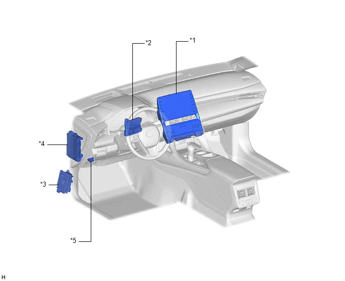
|
*1 | CLIMATE CONTROL SWITCH (RADIO AND DISPLAY RECEIVER ASSEMBLY) |
*2 | AIR CONDITIONING AMPLIFIER ASSEMBLY |
|
*3 | NO. 4 RELAY BLOCK ASSEMBLY - S/HTR F/L FUSE - S/HTR F/R FUSE |
*4 | INSTRUMENT PANEL JUNCTION BLOCK ASSEMBLY - ECU-IG1 NO. 4 FUSE |
|
*5 | DLC3 |
- | - |
ILLUSTRATION
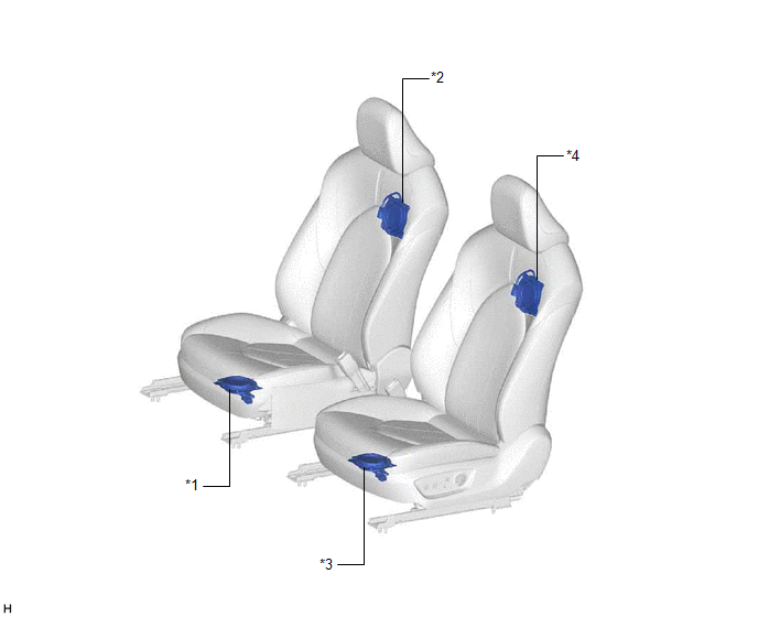
|
*1 | SEAT CUSHION CLIMATE CONTROL BLOWER RH |
*2 | SEATBACK CLIMATE CONTROL BLOWER RH |
|
*3 | SEAT CUSHION CLIMATE CONTROL BLOWER LH |
*4 | SEATBACK CLIMATE CONTROL BLOWER LH |
PRECAUTION
PRECAUTION FOR DISCONNECTING CABLE FROM NEGATIVE AUXILIARY BATTERY TERMINAL
NOTICE:
When disconnecting the cable from the negative (-) auxiliary battery terminal, initialize the following systems after the cable is reconnected.
|
System Name | See Procedure |
|---|---|
|
Lane Departure Alert System (w/ Steering Control) |
|
|
Intelligent Clearance Sonar System | |
|
Parking Assist Monitor System | |
|
Panoramic View Monitor System | |
|
Pre-collision System | |
|
Lighting System (for HV Model with Cornering Light) |
PROBLEM SYMPTOMS TABLE
NOTICE:
If the auxiliary battery voltage becomes low, auxiliary battery load control will operate in order to ensure sufficient power is supplied to the power steering system. In this case, the climate control seat system (for HV model) may not operate.
HINT:
|
Symptom | Suspected Area |
Link |
|---|---|---|
| Seat blower volume is low (front LH seat) |
Check that the air ducts are not disconnected or damaged |
 |
|
Seat cushion climate control blower LH |
- | |
| Seatback climate control blower LH |
- | |
| Seat blower volume is low (front RH seat) |
Check that the air ducts are not disconnected or damaged |
|
|
Seat cushion climate control blower RH |
- | |
| Seatback climate control blower RH |
- | |
| Seat blower volume does not change (front LH seat) |
Climate control switch (Radio and display receiver assembly) |
- |
| Seat cushion climate control blower LH |
- | |
| Seatback climate control blower LH |
- | |
| Air conditioning amplifier assembly |
- | |
| Seat blower volume does not change (front RH seat) |
Climate control switch (Radio and display receiver assembly) |
- |
| Seat cushion climate control blower RH |
- | |
| Seatback climate control blower RH |
- | |
| Air conditioning amplifier assembly |
- | |
| Climate control seat system does not operate |
Refer to the "Climate Control Seat System does not Operate". |
|
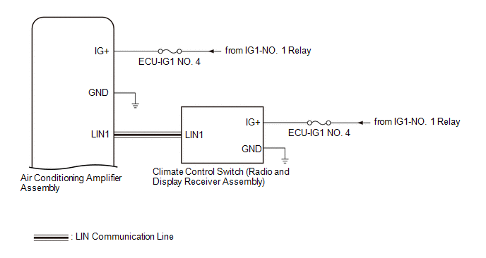
SYSTEM DESCRIPTION
GENERAL
(a) The seat blower has 3 levels of volume, controlled by operating the climate control switch (radio and display receiver assembly).
(b) The climate control switch (radio and display receiver assembly) indicator lights indicate the seat blower operating status.
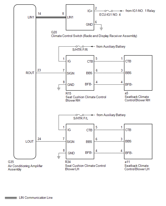
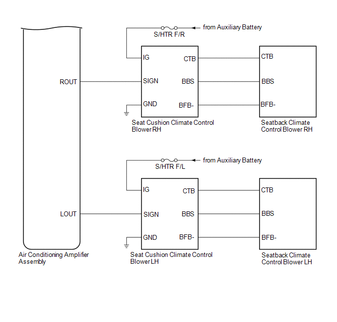
(c) The blowers of both seats are controlled by the air conditioning amplifier assembly.
SYSTEM DIAGRAM
TERMINALS OF ECU
CHECK AIR CONDITIONING AMPLIFIER ASSEMBLY
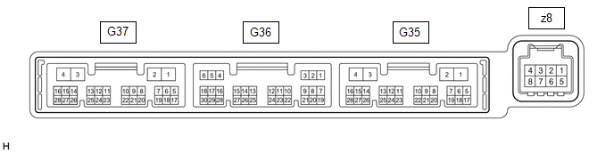
(a) Disconnect the G35 air conditioning amplifier assembly connector.
(b) Measure the voltage and resistance according to the value(s) in the table below.
HINT:
Measure the values on the wire harness side with the connector disconnected.
|
Terminal No. (Symbol) | Wiring Color |
Terminal Description | Condition |
Specified Condition |
|---|---|---|---|---|
|
G35-2 (IG+) - Body ground |
LA-GR - Body ground | Air conditioning amplifier power supply |
Power switch off | Below 1 V |
|
G35-2 (IG+) - Body ground |
LA-GR - Body ground | Air conditioning amplifier power supply |
Power switch on (IG) |
11 to 14 V |
|
G35-4 (GND) - Body ground |
W-B - Body ground | Air conditioning amplifier ground |
Always | Below 1 Ω |
(c) Reconnect the G35 air conditioning amplifier assembly connector.
(d) Check for pulses according to the value(s) in the table below.
|
Terminal No. (Symbol) | Wiring Color |
Terminal Description | Condition |
Specified Condition |
|---|---|---|---|---|
|
G35-24 (LOUT) - Body ground |
G - Body ground | Climate control blower control signal |
| Pulse generation (See waveform) |
|
G35-23 (ROUT) - Body ground |
LG - Body ground | Climate control blower control signal |
| Pulse generation (See waveform) |
|
G35-14 (LIN1) - Body ground |
LG - Body ground | Climate control switch signal |
Power switch on (IG) |
Pulse generation |
(1) Waveform (Reference):
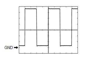 Measurement Condition
 |
Item | Content |
|---|---|
|
Tester Connection |
|
| Tool Setting |
1 V/DIV., 0.5 ms/DIV. |
|
Vehicle Condition |
|
CLIMATE CONTROL SWITCH (RADIO AND DISPLAY RECEIVER ASSEMBLY)

(a) Disconnect the G20 climate control switch (radio and display receiver assembly) connector.
(b) Measure the voltage and resistance according to the value(s) in the table below.
HINT:
Measure the values on the wire harness side with the connector disconnected.
|
Terminal No. (Symbol) | Wiring Color |
Terminal Description | Condition |
Specified Condition |
|---|---|---|---|---|
|
G20-2 (IG+) - Body ground |
GR - Body ground | Climate control switch power supply |
Power switch off | Below 1 V |
|
G20-2 (IG+) - Body ground |
GR - Body ground | Climate control switch power supply |
Power switch on (IG) |
11 to 14 V |
|
G20-6 (GND) - Body ground |
W-B - Body ground | Climate control switch ground |
Always | Below 1 Ω |
(c) Reconnect the G20 climate control switch (radio and display receiver assembly) connector.
(d) Check for pulses according to the value(s) in the table below.
|
Terminal No. (Symbol) | Wiring Color |
Terminal Description | Condition |
Specified Condition |
|---|---|---|---|---|
|
G20-8 (LIN1) - Body ground |
LG - Body ground | Climate control switch signal |
Power switch on (IG) |
Pulse generation |
Toyota Avalon (XX50) 2019-2022 Service & Repair Manual > 2gr-fks Intake / Exhaust: Intake Air Control Valve(for Acis)
On-vehicle InspectionON-VEHICLE INSPECTION PROCEDURE 1. INSPECT INTAKE AIR CONTROL VALVE (for ACIS) (a) Remove the V-bank cover sub-assembly. Click here (b) Disconnect the vacuum hose sub-assembly from the intake air control valve (for ACIS). (c) Connect a hose and vacuum pump to the intake air con ...