TERMINALS OF ECU CHECK AIR CONDITIONING AMPLIFIER ASSEMBLY
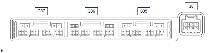 (a) Disconnect the G35 air conditioning amplifier assembly connector.
(b) Measure the voltage and resistance according to the value(s) in the table below.
HINT: Measure the values on the wire harness side with the connector disconnected. |
Terminal No. (Symbol) | Wiring Color |
Terminal Description | Condition |
Specified Condition | |
G35-2 (IG+) - Body ground |
LA-GR - Body ground | Air conditioning amplifier power supply |
Power switch off | Below 1 V | |
G35-2 (IG+) - Body ground |
LA-GR - Body ground | Air conditioning amplifier power supply |
Power switch on (IG) |
11 to 14 V | |
G35-4 (GND) - Body ground |
W-B - Body ground | Air conditioning amplifier ground |
Always | Below 1 Ω |
(c) Reconnect the G35 air conditioning amplifier assembly connector. (d) Check for pulses according to the value(s) in the table below. |
Terminal No. (Symbol) | Wiring Color |
Terminal Description | Condition |
Specified Condition | |
G35-24 (LOUT) - Body ground |
G - Body ground | Climate control blower control signal |
- Power switch on (IG)
- Climate control switch (radio and display receiver assembly) (for LH) on
(blower position)
| Pulse generation
(See waveform) | |
G35-23 (ROUT) - Body ground |
LG - Body ground | Climate control blower control signal |
- Power switch on (IG)
- Climate control switch (radio and display receiver assembly) (for RH) on
(blower position)
| Pulse generation
(See waveform) | |
G35-14 (LIN1) - Body ground |
LG - Body ground | Climate control switch signal |
Power switch on (IG) |
Pulse generation | (1) Waveform (Reference):
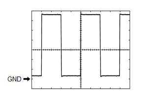 Measurement Condition Measurement Condition |
Item | Content | |
Tester Connection |
- G35-24 (LOUT) - Body ground
- G35-23 (ROUT) - Body ground
| | Tool Setting |
1 V/DIV., 0.5 ms/DIV. | |
Vehicle Condition |
- Power switch on (IG)
- Climate control switch (radio and display receiver assembly) on
(blower position)
| CLIMATE CONTROL SWITCH (RADIO AND DISPLAY RECEIVER ASSEMBLY)
 (a) Disconnect the G20 climate control switch (radio and display receiver assembly) connector.
(b) Measure the voltage and resistance according to the value(s) in the table below.
HINT: Measure the values on the wire harness side with the connector disconnected. |
Terminal No. (Symbol) | Wiring Color |
Terminal Description | Condition |
Specified Condition | |
G20-2 (IG+) - Body ground |
GR - Body ground | Climate control switch power supply |
Power switch off | Below 1 V | |
G20-2 (IG+) - Body ground |
GR - Body ground | Climate control switch power supply |
Power switch on (IG) |
11 to 14 V | |
G20-6 (GND) - Body ground |
W-B - Body ground | Climate control switch ground |
Always | Below 1 Ω |
(c) Reconnect the G20 climate control switch (radio and display receiver assembly) connector.
(d) Check for pulses according to the value(s) in the table below. |
Terminal No. (Symbol) | Wiring Color |
Terminal Description | Condition |
Specified Condition | |
G20-8 (LIN1) - Body ground |
LG - Body ground | Climate control switch signal |
Power switch on (IG) |
Pulse generation | | 

