COMPONENTS
ILLUSTRATION
|
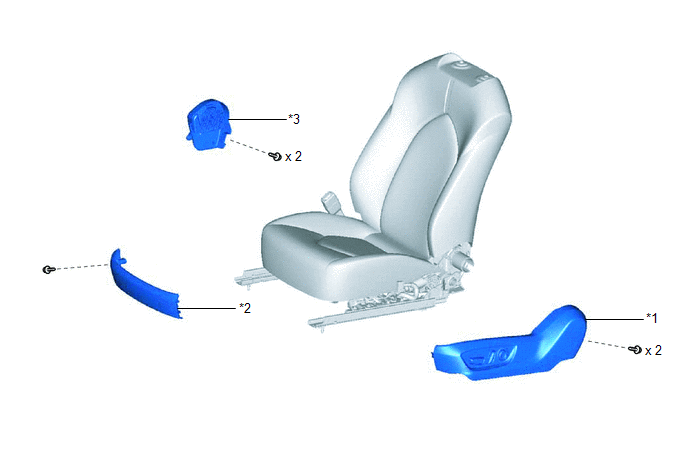
*1 | FRONT SEAT CUSHION SHIELD |
*2 | FRONT SEAT FRONT CUSHION SHIELD |
|
*3 | FRONT SEAT INNER CUSHION SHIELD |
- | - |
ILLUSTRATION
|
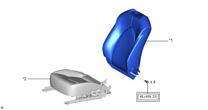
*1 | SEPARATE TYPE FRONT SEATBACK ASSEMBLY |
*2 | SEPARATE TYPE FRONT SEAT CUSHION ASSEMBLY |
 |
Tightening torque for "Major areas involving basic vehicle performance such as moving/turning/stopping": N*m (kgf*cm, ft.*lbf) |
- | - |
ILLUSTRATION
|
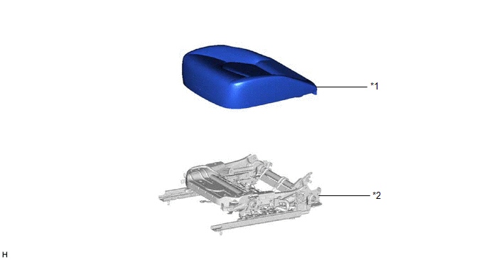
*1 | SEPARATE TYPE FRONT SEAT CUSHION COVER WITH PAD |
*2 | SEPARATE TYPE FRONT SEAT CUSHION SPRING ASSEMBLY |
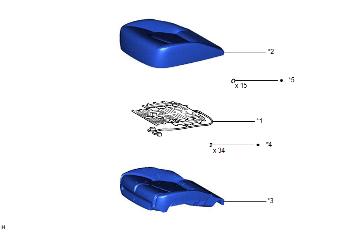
ILLUSTRATION
|
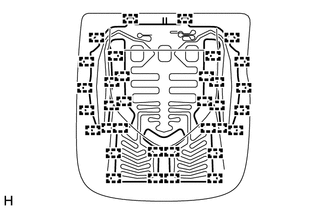
*1 | FRONT SEAT CUSHION HEATER ASSEMBLY |
*2 | SEPARATE TYPE FRONT SEAT CUSHION COVER |
|
*3 | SEPARATE TYPE FRONT SEAT CUSHION PAD |
*4 | TAG PIN |
|
*5 | HOG RING |
- | - |
|
● | Non-reusable part |
- | - |
INSTALLATION
CAUTION / NOTICE / HINT
CAUTION:
Wear protective gloves. Sharp areas on the parts may injure your hands.
HINT:
PROCEDURE
1. INSTALL FRONT SEAT CUSHION HEATER ASSEMBLY
| (a) Install the front seat cushion heater assembly to the separate type front seat cushion cover with 34 new tag pins. |
|
2. INSTALL SEPARATE TYPE FRONT SEAT CUSHION COVER
Click here

3. INSTALL SEPARATE TYPE FRONT SEAT CUSHION COVER WITH PAD
Click here
4. INSTALL SEPARATE TYPE FRONT SEATBACK ASSEMBLY
Click here
5. INSTALL FRONT SEAT INNER CUSHION SHIELD
Click here
6. INSTALL FRONT SEAT CUSHION SHIELD
Click here
7. INSTALL FRONT SEAT FRONT CUSHION SHIELD
Click here
8. CONNECT SEPARATE TYPE FRONT SEATBACK COVER
Click here
9. INSTALL FRONT SEAT ASSEMBLY
Click here
REMOVAL
CAUTION / NOTICE / HINT
The necessary procedures (adjustment, calibration, initialization, or registration) that must be performed after parts are removed and installed, or replaced during front seat cushion heater assembly removal/installation are shown below.
Necessary Procedures After Parts Removed/Installed/Replaced (for Gasoline Model)|
Replaced Part or Performed Procedure |
Necessary Procedure | Effect/Inoperative Function when Necessary Procedure not Performed |
Link |
|---|---|---|---|
|
*: When performing learning using the Techstream.
Click here | |||
|
Disconnect cable from negative auxiliary battery terminal |
Perform steering sensor zero point calibration |
Lane departure alert system (w/ Steering Control) |
|
|
Pre-collision system | |||
|
Intelligent clearance sonar system* | |||
|
Lighting system (for Gasoline Model with Cornering Light) | |||
|
Memorize steering angle neutral point |
Parking assist monitor system |
| |
|
Panoramic view monitor system |
| ||
| Zero point calibration (Occupant classification system) |
|
|
| Initialize position control ECU |
Front power seat control system |
|
|
Replaced Part or Performed Procedure |
Necessary Procedure | Effect/Inoperative Function when Necessary Procedure not Performed |
Link |
|---|---|---|---|
|
*: When performing learning using the Techstream.
Click here | |||
|
Disconnect cable from negative auxiliary battery terminal |
Perform steering sensor zero point calibration |
Lane departure alert system (w/ Steering Control) |
|
|
Pre-collision system | |||
|
Intelligent clearance sonar system* | |||
|
Lighting system (for HV Model with Cornering Light) | |||
|
Memorize steering angle neutral point |
Parking assist monitor system |
| |
|
Panoramic view monitor system |
| ||
| Zero point calibration (Occupant classification system) |
|
|
| Initialize position control ECU |
Front power seat control system |
|
CAUTION:
for Gasoline Model: Click here 
for HV Model: Click here
HINT:
PROCEDURE
1. REMOVE FRONT SEAT ASSEMBLY
Click here
2. DISCONNECT SEPARATE TYPE FRONT SEATBACK COVER
Click here
3. REMOVE FRONT SEAT FRONT CUSHION SHIELD
Click here
4. REMOVE FRONT SEAT CUSHION SHIELD
Click here
5. REMOVE FRONT SEAT INNER CUSHION SHIELD
Click here
6. REMOVE SEPARATE TYPE FRONT SEATBACK ASSEMBLY
Click here
7. REMOVE SEPARATE TYPE FRONT SEAT CUSHION COVER WITH PAD
Click here
8. REMOVE SEPARATE TYPE FRONT SEAT CUSHION COVER
Click here
9. REMOVE FRONT SEAT CUSHION HEATER ASSEMBLY
| (a) Remove the 34 tag pins and front seat cushion heater assembly from the separate type front seat cushion cover. |
|
Toyota Avalon (XX50) 2019-2022 Service & Repair Manual > Window / Glass: Quarter Window Glass
Components COMPONENTS ILLUSTRATION *A for HV Model - - *1 LUGGAGE TRIM SERVICE HOLE COVER - - ILLUSTRATION *A for Gasoline Model *B for HV Model *1 QUARTER WINDOW ASSEMBLY *2 REAR CENTER SEAT OUTER BELT ASSEMBLY *3 REAR DOOR OPENING TRIM WEATHERSTRIP *4 REAR SEAT CUSHION ASSEMBLY *5 REAR SEAT CUSHIO ...