DESCRIPTION The front side squib LH circuit consists of the airbag ECU assembly and front seat airbag assembly LH. The airbag ECU assembly uses this circuit to deploy the airbag when deployment conditions are met. These DTCs are stored when a malfunction is detected in the front side squib LH circuit.
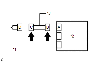
WIRING DIAGRAM 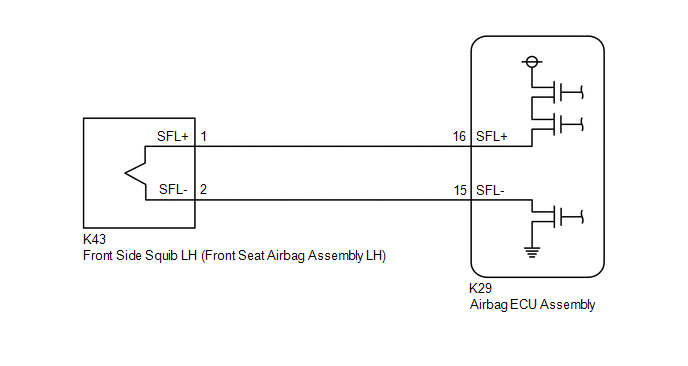 CAUTION / NOTICE / HINT NOTICE: After turning the engine switch off, waiting time may be required before disconnecting the cable from the negative (-) battery terminal. Therefore, make sure to read the disconnecting the cable from the negative (-) battery terminal notices before proceeding with work. Click here
HINT:
PROCEDURE
(b) Disconnect the cable from the negative (-) battery terminal. CAUTION: Wait at least 90 seconds after disconnecting the cable from the negative (-) battery terminal to disable the SRS system. (c) Check that the connectors are properly connected to the front seat airbag assembly LH and airbag ECU assembly. OK: The connectors are properly connected. HINT: If the connectors are not properly connected, reconnect the connectors and proceed to the next inspection. (d) Disconnect the connectors from the front seat airbag assembly LH and airbag ECU assembly. (e) Check that the terminals of the connectors are not deformed or damaged. OK: The terminals are not deformed or damaged. (f) Check that the short springs of the activation prevention mechanism of the floor wire connector are not deformed or damaged. OK: The short springs are not deformed or damaged.
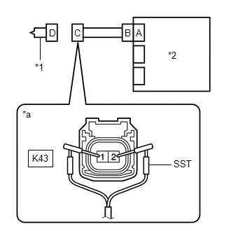
(b) Connect SST (resistance 2.1 Ω) to connector C. CAUTION: Never connect a tester to the front seat airbag assembly LH for measurement, as this may lead to a serious injury due to airbag deployment. NOTICE:
SST: 09843-18061 (c) Connect the cable to the negative (-) battery terminal. (d) Turn the engine switch on (IG), and wait for at least 60 seconds. (e) Clear the DTCs stored in memory. Body Electrical > SRS Airbag > Clear DTCs(f) Turn the engine switch off. (g) Turn the engine switch on (IG), and wait for at least 60 seconds. (h) Check for DTCs. Body Electrical > SRS Airbag > Trouble CodesOK: DTC B1825, B1826, B1827 or B1828 is not output. HINT: Codes other than DTCs B1825, B1826, B1827 and B1828 may be output at this time, but they are not related to this check. (i) Turn the engine switch off. (j) Disconnect the cable from the negative (-) battery terminal. CAUTION: Wait at least 90 seconds after disconnecting the cable from the negative (-) battery terminal to disable the SRS system. (k) Disconnect SST from connector C.
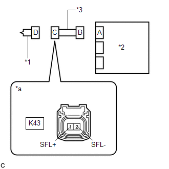
(b) Check for a short to B+ in the circuit. (1) Connect the cable to the negative (-) battery terminal. (2) Turn the engine switch on (IG). (3) Measure the voltage according to the value(s) in the table below. Standard Voltage:
(4) Turn the engine switch off. (5) Disconnect the cable from the negative (-) battery terminal. CAUTION: Wait at least 90 seconds after disconnecting the cable from the negative (-) battery terminal to disable the SRS system. (c) Check for an open in the circuit. (1) Measure the resistance according to the value(s) in the table below. Standard Resistance:
(d) Check for a short to ground in the circuit. (1) Measure the resistance according to the value(s) in the table below. Standard Resistance:
(e) Check for a short in the circuit. (1) Release the activation prevention mechanism built into connector B. Click here (2) Measure the resistance according to the value(s) in the table below. Standard Resistance:
(3) Restore the released activation prevention mechanism of connector B to the original condition.
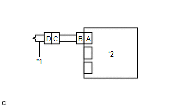
(b) Connect the cable to the negative (-) battery terminal. (c) Turn the engine switch on (IG), and wait for at least 60 seconds. (d) Clear the DTCs stored in memory. Body Electrical > SRS Airbag > Clear DTCs(e) Turn the engine switch off. (f) Turn the engine switch on (IG), and wait for at least 60 seconds. (g) Check for DTCs. Body Electrical > SRS Airbag > Trouble CodesOK: DTC B1825, B1826, B1827 or B1828 is not output. HINT: Codes other than DTCs B1825, B1826, B1827 and B1828 may be output at this time, but they are not related to this check.
|
Toyota Avalon (XX50) 2019-2022 Owners Manual > Adjusting the steering
wheel and mirrors: Steering wheel
Adjustment procedure Manual type 1. Hold the steering wheel and push the lever down. 2. Adjust to the ideal position by moving the steering wheel horizontally and vertically. After adjustment, pull the lever up to secure the steering wheel. Power type Operating the switch moves the steering wheel in ...