DESCRIPTION The driver side knee airbag squib circuit consists of the airbag ECU assembly and lower No. 1 instrument panel airbag assembly. The airbag ECU assembly uses this circuit to deploy the airbag when deployment conditions are met. These DTCs are stored when a malfunction is detected in the driver side knee airbag squib circuit.
WIRING DIAGRAM 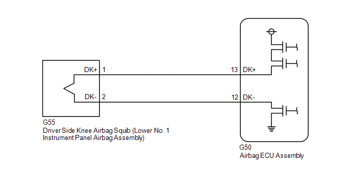 CAUTION / NOTICE / HINT NOTICE: After turning the engine switch off, waiting time may be required before disconnecting the cable from the negative (-) battery terminal. Therefore, make sure to read the disconnecting the cable from the negative (-) battery terminal notices before proceeding with work. Click here
HINT:
PROCEDURE
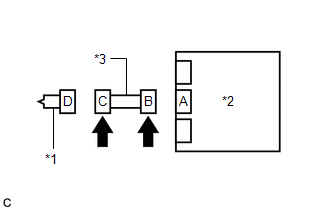
(b) Disconnect the cable from the negative (-) battery terminal. CAUTION: Wait at least 90 seconds after disconnecting the cable from the negative (-) battery terminal to disable the SRS system. (c) Check that the connectors are properly connected to the lower No. 1 instrument panel airbag assembly and airbag ECU assembly. OK: The connectors are properly connected. HINT: If the connectors are not properly connected, reconnect the connectors and proceed to the next inspection. (d) Disconnect the connectors from the lower No. 1 instrument panel airbag assembly and airbag ECU assembly. (e) Check that the terminals of the connectors are not deformed or damaged. OK: The terminals are not deformed or damaged. (f) Check that the instrument panel wire connector (on the lower No. 1 instrument panel airbag assembly side) is not loose, deformed or damaged. OK: The airbag connector locking button is not disengaged, and the claw of the lock is not deformed or damaged. (g) Check that the short springs of the activation prevention mechanism of the instrument panel wire connector are not deformed or damaged. OK: The short springs are not deformed or damaged.
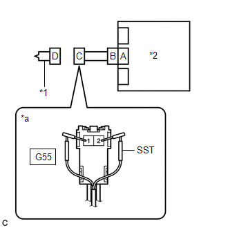
(b) Connect SST (resistance 2.1 Ω) to connector C. CAUTION: Never connect a tester to the lower No. 1 instrument panel airbag assembly for measurement, as this may lead to a serious injury due to airbag deployment. NOTICE:
SST: 09843-18061 (c) Connect the cable to the negative (-) battery terminal. (d) Turn the engine switch on (IG), and wait for at least 60 seconds. (e) Clear the DTCs stored in memory. Body Electrical > SRS Airbag > Clear DTCs(f) Turn the engine switch off. (g) Turn the engine switch on (IG), and wait for at least 60 seconds. (h) Check for DTCs. Body Electrical > SRS Airbag > Trouble CodesOK: DTC B1860, B1861, B1862 or B1863 is not output. HINT: Codes other than DTCs B1860, B1861, B1862 and B1863 may be output at this time, but they are not related to this check. (i) Turn the engine switch off. (j) Disconnect the cable from the negative (-) battery terminal. CAUTION: Wait at least 90 seconds after disconnecting the cable from the negative (-) battery terminal to disable the SRS system. (k) Disconnect SST from connector C.
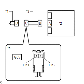
(b) Check for a short to B+ in the circuit. (1) Connect the cable to the negative (-) battery terminal. (2) Turn the engine switch on (IG). (3) Measure the voltage according to the value(s) in the table below. Standard Voltage:
(4) Turn the engine switch off. (5) Disconnect the cable from the negative (-) battery terminal. CAUTION: Wait at least 90 seconds after disconnecting the cable from the negative (-) battery terminal to disable the SRS system. (c) Check for an open in the circuit. (1) Measure the resistance according to the value(s) in the table below. Standard Resistance:
(d) Check for a short to ground in the circuit. (1) Measure the resistance according to the value(s) in the table below. Standard Resistance:
(e) Check for a short in the circuit. (1) Release the activation prevention mechanism built into connector B. Click here (2) Measure the resistance according to the value(s) in the table below. Standard Resistance:
(3) Restore the released activation prevention mechanism of connector B to the original condition.
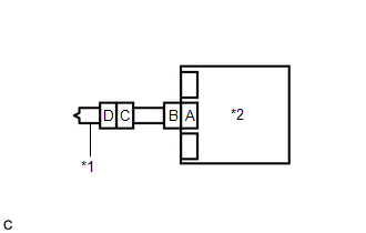
(b) Connect the cable to the negative (-) battery terminal. (c) Turn the engine switch on (IG), and wait for at least 60 seconds. (d) Clear the DTCs stored in memory. Body Electrical > SRS Airbag > Clear DTCs(e) Turn the engine switch off. (f) Turn the engine switch on (IG), and wait for at least 60 seconds. (g) Check for DTCs. Body Electrical > SRS Airbag > Trouble CodesOK: DTC B1860, B1861, B1862 or B1863 is not output. HINT: Codes other than DTCs B1860, B1861, B1862 and B1863 may be output at this time, but they are not related to this check.
|
Toyota Avalon (XX50) 2019-2022 Owners Manual > Steps to take in an
emergency: If the electronic key
does not operate
properly
If communication between the electronic key and vehicle is interrupted or the electronic key cannot be used because the battery is depleted, the smart key system and wireless remote control cannot be used. In such cases, the doors and trunk can be opened and the engine can be started by following t ...