DESCRIPTION The SRS warning light is located in the combination meter assembly. When the SRS is normal, the SRS warning light comes on for approximately 6 seconds after the engine switch is turned from off to on (IG), and then turns off automatically. If there is a malfunction in the SRS, the SRS warning light comes on to inform the driver of a problem. If a malfunction occurs in the airbag ECU assembly, combination meter assembly or wire harness connected to the airbag ECU assembly or combination meter assembly, the SRS warning light turns on. The SRS is equipped with a voltage-increase circuit (DC-DC converter) in the airbag ECU assembly in case the power source voltage drops. When the battery voltage drops, the voltage-increase circuit (DC-DC converter) functions to increase the voltage of the SRS to normal voltage. A malfunction in this circuit is not stored in the airbag ECU assembly. The SRS warning light automatically turns off when the power source voltage returns to normal. The signal to illuminate the SRS warning light is transmitted from the airbag ECU assembly to the combination meter assembly via CAN communication. WIRING DIAGRAM 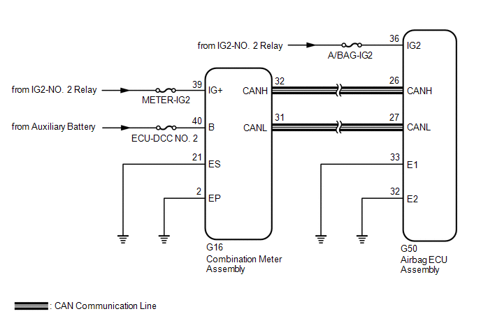 CAUTION / NOTICE / HINT NOTICE:
PROCEDURE
(a) Measure the voltage of the battery. Standard Voltage: 11 to 14 V
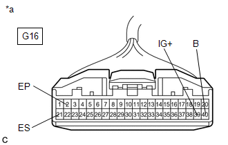
(a) Turn the engine switch off. (b) Disconnect the cable from the negative (-) battery terminal. CAUTION: Wait at least 90 seconds after disconnecting the cable from the negative (-) battery terminal to disable the SRS system. (c) Check that the connector is properly connected to the combination meter assembly. OK: The connector is properly connected. HINT: If the connector is not properly connected, reconnect the connector and proceed to the next inspection. (d) Disconnect the connector from the combination meter assembly. (e) Check that the terminals of the connector are not deformed or damaged. OK: The terminals are not deformed or damaged.
(b) Turn the engine switch on (IG). (c) Measure the voltage according to the value(s) in the table below. Standard Voltage:
(d) Turn the engine switch off. (e) Measure the resistance according to the value(s) in the table below. Standard Resistance:
(a) Disconnect the cable from the negative (-) battery terminal. CAUTION: Wait at least 90 seconds after disconnecting the cable from the negative (-) battery terminal to disable the SRS system. (b) Connect the connector to the combination meter assembly. (c) Disconnect the connector from the airbag ECU assembly. (d) Connect the cable to the negative (-) battery terminal. (e) Turn the engine switch on (IG) and check the SRS warning light condition. OK: After the primary check period, the SRS warning light turns off for approximately 10 seconds and then turns back on. HINT: The primary check period is approximately 6 seconds after the engine switch is turned on (IG).
|
Toyota Avalon (XX50) 2019-2022 Service & Repair Manual > Steering Column Assembly(for Power Tilt And Power Telescopic Steering Column): Inspection
INSPECTION PROCEDURE 1. INSPECT STEERING COLUMN ASSEMBLY (a) Check that the 2 bushings are securely installed to the steering column assembly. HINT: If the bushings are deformed, missing or damaged, replace the steering column assembly with a new one. ...