COMPONENTS
ILLUSTRATION
|
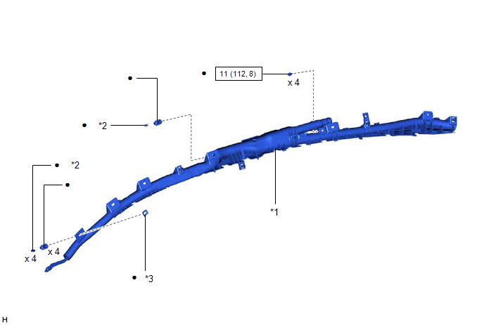
*1 | CURTAIN SHIELD AIRBAG ASSEMBLY |
*2 | PIN |
|
*3 | SPACER |
- | - |
 |
N*m (kgf*cm, ft.*lbf): Specified torque |
● | Non-reusable part |
DISPOSAL
CAUTION / NOTICE / HINT
CAUTION:
Before performing pre-disposal deployment of any SRS part, review and closely follow all applicable environmental and hazardous material regulations. Pre-disposal deployment may be considered hazardous material treatment.
PROCEDURE
1. PRECAUTION
CAUTION:
HINT:
When scrapping a vehicle equipped with an SRS or disposing of the curtain shield airbag assembly, be sure to deploy the airbag first in accordance with the following procedure. If any abnormality occurs with the airbag deployment, contact the Service Department of TOYOTA MOTOR SALES, U.S.A., INC.
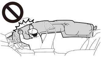
2. DISPOSE OF CURTAIN SHIELD AIRBAG ASSEMBLY (When Installed to Vehicle)
NOTICE:
HINT:
Prepare a 12 V battery as the power source to deploy the airbag.
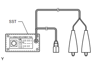
| (a) Check the function of SST. Click here
SST: 09082-00700 |
|
(b) Refer to Precaution.
for Gasoline Model: Click here

for HV Model: Click here
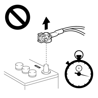
(c) Disconnect the cable from the negative (-) auxiliary battery terminal.
CAUTION:
Wait at least 90 seconds after disconnecting the cable from the negative (-) auxiliary battery terminal to disable the SRS system.

(d) Remove the roof headlining assembly.
Click here
(e) Disconnect the curtain shield airbag assembly connector.
(1) Using a screwdriver with its tip wrapped with protective tape, disconnect the airbag connector.
NOTICE:
When disconnecting any airbag connector, take care not to damage the airbag wire harness.
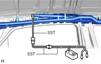
(f) Install SST.
CAUTION:
Check that there is no looseness in the curtain shield airbag assembly.
| (1) After connecting the following SST to each other, connect them to the curtain shield airbag assembly. SST: 09082-00700 SST: 09082-00802 09082-10801 09082-20801 NOTICE: To avoid damaging the SST connector or wire harness, do not lock the secondary lock of the twin lock. |
|
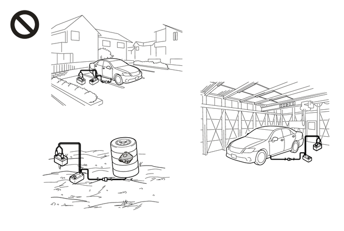
| (2) Move SST at least 10 m (32.8 ft.) away from the rear side window of the vehicle. |
|
(3) Maintaining sufficient clearance for the SST wire harness in the rear side window, close all doors and windows of the vehicle.
NOTICE:
Take care not to damage the SST wire harness.
(4) Connect the red clip of SST to the positive (+) battery terminal and the black clip of SST to the negative (-) battery terminal.
(g) Deploy the airbag.
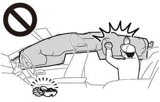
(1) Check that no one is inside the vehicle or within a 10 m (32.8 ft.) radius of the vehicle.
(2) Press the SST activation switch to deploy the airbag.
CAUTION:
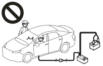
HINT:
The airbag is deployed as the LED of the SST activation switch comes on.
3. DISPOSE OF CURTAIN SHIELD AIRBAG ASSEMBLY (When not Installed to Vehicle)
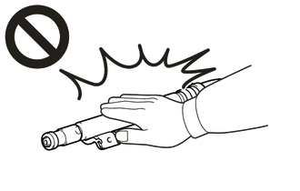
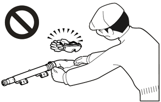
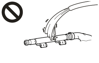
NOTICE:
Be sure to perform the following procedure when deploying the airbag.
HINT:
Prepare a 12 V battery as the power source to deploy the airbag.
| (a) Check the function of SST. Click here
SST: 09082-00700 |
|
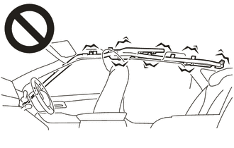
(b) Remove the curtain shield airbag assembly.
Click here
CAUTION:

 |
Deployment Side |
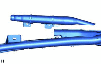
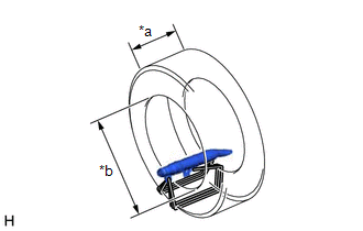
| (c) Cut off the deployment section of the curtain shield airbag assembly. |
|
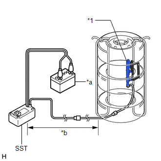
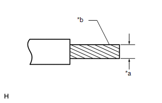
(d) Using braided wire, tie down the curtain shield airbag assembly to an unneeded tire.
|
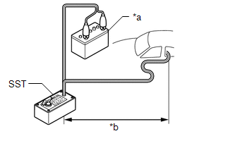
*a | Wire Diameter |
|
*b | Stripped Wire Cross Sectional Area |
Wire:
Stripped Wire Cross Sectional Area
1.25 mm2 (0.0019 in.2) or more
CAUTION:
If the wire is too thin or an alternative object is used to tie down the curtain shield airbag assembly, it may snap when the airbag is deployed. Always use a wire for vehicle use with a cross sectional area of at least 1.25 mm2 (0.0019 in.2).
HINT:
To calculate the cross sectional area of the stripped wire:
Cross sectional area = 3.14 x (Diameter)2 / 4
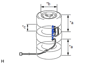
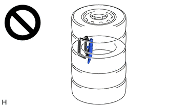
| (1) Position the curtain shield airbag assembly inside the tire as shown in the illustration. Minimum Tire Size: Width 185 mm (7.28 in.) Inner Diameter 360 mm (1.18 ft.) CAUTION: Make sure that the wires are tight. If there is slack in the wires, the curtain shield airbag assembly may break loose when the airbag is deployed. NOTICE: The tire may be damaged by the airbag deployment, so use an unneeded tire. |
|
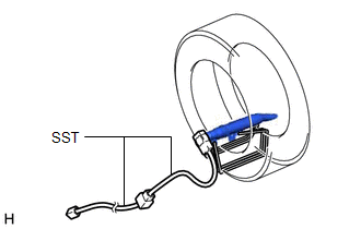
(e) Install SST.
| (1) After connecting the following SST to each other, connect them to the curtain shield airbag assembly. SST: 09082-00802 09082-10801 09082-20801 |
|
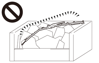
(f) Place the tires.
CAUTION:
Do not face the deployment side of the curtain shield airbag assembly toward the ground.
| (1) Place at least 2 tires under the tire to which the curtain shield airbag assembly is tied. Minimum Tire Size: Width 185 mm (7.28 in.) Inner Diameter 360 mm (1.18 ft.) NOTICE: Do not place the SST connector under the tire because it could be damaged. |
|
(2) Place at least 2 tires onto the tire to which the curtain shield airbag assembly is tied. The top tire should have a wheel installed.
NOTICE:
The wheel and tires may be damaged by the airbag deployment, so use an unneeded wheel and tires.
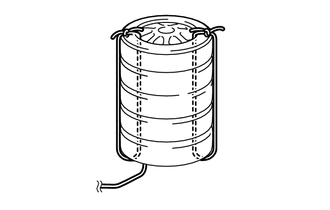
| (3) Tie the tires together with 2 wires. CAUTION: Make sure that the wires are tight. Looseness in the wires will result in the tires breaking loose when the airbag is deployed. |
|
(g) Install SST.
| (1) Connect the SST connector. SST: 09082-00700 NOTICE: To avoid damaging the SST connector or wire harness, do not lock the secondary lock of the twin lock. Also, secure some slack for the SST wire harness inside the tire. |
|
(2) Move SST at least 10 m (32.8 ft.) away from the airbag tied down to the tire.
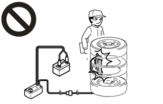
(h) Deploy the airbag.
(1) Connect the red clip of SST to the positive (+) battery terminal and the black clip of SST to the negative (-) battery terminal.
(2) Check that no one is within a 10 m (32.8 ft.) radius of the tire to which the curtain shield airbag assembly is tied.
(3) Press the SST activation switch to deploy the airbag.
CAUTION:
Before deployment, make sure that no one is near the airbag.
HINT:
The airbag is deployed as the LED of the SST activation switch comes on.
(i) Dispose of the curtain shield airbag assembly.
CAUTION:
(1) Remove the curtain shield airbag assembly from the tire.
(2) Place the curtain shield airbag assembly in a plastic bag, tie it tightly, and dispose of it according to local regulations.
INSTALLATION
CAUTION / NOTICE / HINT
HINT:
PROCEDURE
1. INSTALL CURTAIN SHIELD AIRBAG ASSEMBLY
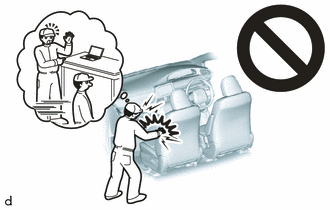
NOTICE:
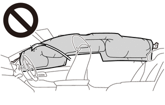
When installing a curtain shield airbag assembly, have assistants hold it to prevent it from bending.
(a) Check that the engine switch (for Gasoline Model) or power switch (for HV Model) is off.
(b) Check that the cable is disconnected from the negative (-) auxiliary battery terminal.
CAUTION:
Wait at least 90 seconds after disconnecting the cable from the negative (-) auxiliary battery terminal to disable the SRS system.

(c) Insert the 3 hooks and install the curtain shield airbag assembly with 4 new bolts, a new spacer, 4 new clips (A) with pins and a new clip (B) with pin, and engage the 4 clips (C).
Torque:
11 N·m {112 kgf·cm, 8 ft·lbf}
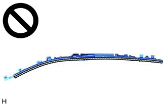
NOTICE:
Do not twist the curtain shield airbag assembly when installing it.
HINT:
Engage the 2 claws to install each new clip (A) and (B).
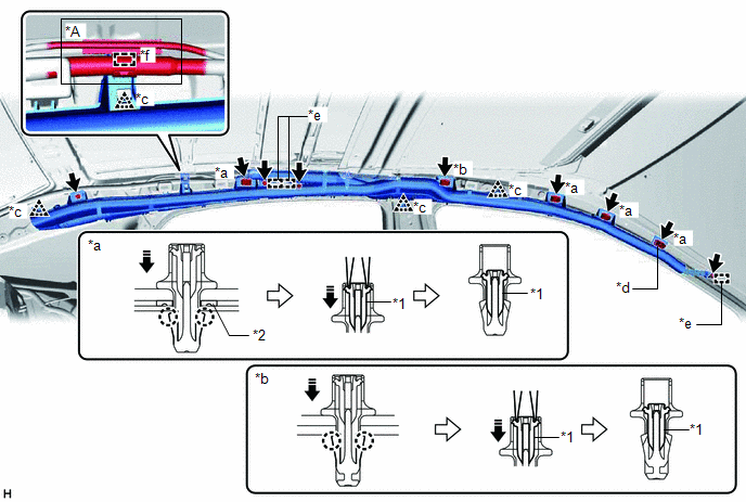
|
*A | w/ Sliding Roof |
- | - |
|
*1 | Pin | *2 |
Spacer |
| *a |
Clip (A) | *b |
Clip (B) |
| *c |
Clip (C) | *d |
Spacer Location |
|
*e | Hook |
*f | Clamp |
 |
Install in this Direction |
- | - |
(d) Using needle nose pliers, push the 5 pins into the 4 clips (A) and clip (B).
NOTICE:
(e) w/ Sliding Roof:
(1) Engage the clamp.
(f) Connect the airbag connector.
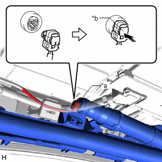
|
*a | Airbag Connector |
|
*b | Airbag Connector Locking Button |
|
|
Push in this Direction |
NOTICE:
When connecting any airbag connector, take care not to damage the airbag wire harness.
(g) Push in the airbag connector locking button to install the airbag connector.
2. INSTALL ROOF HEADLINING ASSEMBLY
Click here

3. PERFORM DIAGNOSTIC SYSTEM CHECK
for Gasoline Model: Click here
for HV Model: Click here
ON-VEHICLE INSPECTION
CAUTION / NOTICE / HINT
CAUTION:
Be sure to correctly follow the removal and installation procedures for the curtain shield airbag assemblies.
PROCEDURE
1. INSPECT CURTAIN SHIELD AIRBAG ASSEMBLY (for Vehicle not Involved in Collision)
(a) Perform a diagnostic system check.
for Gasoline Model: Click here

for HV Model: Click here
(b) Visually check for defects with the curtain shield airbag assemblies installed to the vehicle.
HINT:
The defects are as follows:
OK:
No defects are found.
If any defects are found, replace each pillar garnish or the roof headlining assembly with a new one.
2. INSPECT CURTAIN SHIELD AIRBAG ASSEMBLY (for Vehicle Involved in Collision and Airbag not Deployed)
(a) Perform a diagnostic system check.
for Gasoline Model: Click here
for HV Model: Click here
(b) Visually check for defects with the curtain shield airbag assemblies removed from the vehicle.
HINT:
The defects are as follows:
OK:
No defects are found.
If any defects are found, replace the curtain shield airbag assembly with a new one.
REMOVAL
CAUTION / NOTICE / HINT
The necessary procedures (adjustment, calibration, initialization or registration) that must be performed after parts are removed and installed, or replaced during curtain shield airbag assembly removal/installation are shown below.
Necessary Procedures After Parts Removed/Installed/Replaced (for Gasoline Model)|
Replaced Part or Performed Procedure |
Necessary Procedure | Effect/Inoperative Function when Necessary Procedure not Performed |
Link |
|---|---|---|---|
|
*: When performing learning using the Techstream.
Click here | |||
|
Disconnect cable from negative auxiliary battery terminal |
Perform steering sensor zero point calibration |
Lane Departure Alert System (w/ Steering Control) |
|
|
Pre-collision System | |||
|
Intelligent Clearance Sonar System* | |||
|
Lighting System (for Gasoline Model with Cornering Light) | |||
|
Memorize steering angle neutral point |
Parking Assist Monitor System |
| |
|
Panoramic View Monitor System |
| ||
|
Front passenger seat | Zero point calibration (Occupant classification system) |
|
|
|
Replaced Part or Performed Procedure |
Necessary Procedure | Effect/Inoperative Function when Necessary Procedure not Performed |
Link |
|---|---|---|---|
|
*: When performing learning using the Techstream.
Click here | |||
|
Disconnect cable from negative auxiliary battery terminal |
Perform steering sensor zero point calibration |
Lane Departure Alert System (w/ Steering Control) |
|
|
Pre-collision System | |||
|
Intelligent Clearance Sonar System* | |||
|
Lighting System (for HV Model with Cornering Light) | |||
|
Memorize steering angle neutral point |
Parking Assist Monitor System |
| |
|
Panoramic View Monitor System |
| ||
|
Front passenger seat | Zero point calibration (Occupant classification system) |
|
|
HINT:
PROCEDURE
1. PRECAUTION
CAUTION:
Be sure to read Precaution thoroughly before servicing.
for Gasoline Model: Click here

for HV Model: Click here
NOTICE:
After turning the engine switch (for Gasoline Model) or power switch (for HV Model) off, waiting time may be required before disconnecting the cable from the negative (-) auxiliary battery terminal. Therefore, make sure to read the disconnecting the cable from the negative (-) auxiliary battery terminal notices before proceeding with work.
Click here
2. REMOVE ROOF HEADLINING ASSEMBLY
Click here
3. REMOVE CURTAIN SHIELD AIRBAG ASSEMBLY
CAUTION:
When storing the curtain shield airbag assembly, keep the airbag deployment side facing upward.
 |
Deployment Side |
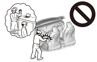
NOTICE:
When removing the curtain shield airbag assembly, have assistants hold it to prevent it from bending.
(a) Check that the engine switch (for Gasoline Model) or power switch (for HV Model) is off.
(b) Check that the cable is disconnected from the negative (-) auxiliary battery terminal.
CAUTION:
Wait at least 90 seconds after disconnecting the cable from the negative (-) auxiliary battery terminal to disable the SRS system.
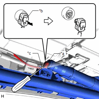
(c) Using a screwdriver with its tip wrapped with protective tape, release the airbag connector locking button and disconnect the airbag connector.
|
*a | Airbag Connector |
|
*b | Airbag Connector Locking Button |
|
*c | Protective Tape |
 |
Release in this Direction |
NOTICE:
When disconnecting any airbag connector, take care not to damage the airbag wire harness.
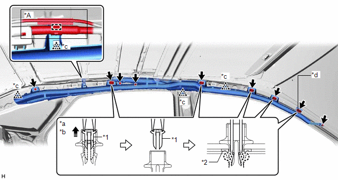
(d) w/ Sliding Roof:
(1) Disengage the clamp.
|
*A | w/ Sliding Roof |
- | - |
|
*1 | Pin | *2 |
Spacer |
| *a |
Clip (A) | *b |
Clip (B) |
| *c |
Clip (C) | *d |
Spacer Location |
|
|
Remove in this Direction |
- | - |
(e) Using needle nose pliers, remove the 5 pins from the 4 clips (A) and clip (B).
NOTICE:
Do not damage the pins.
(f) Using 2 screwdrivers, disengage the 2 claws of each clip (A) and (B), and separate the 4 clips (A) and clip (B) from the vehicle body as shown in the illustration.
HINT:
Separate the 4 clips (A), clip (B) and curtain shield airbag assembly from the vehicle body as a unit.
(g) Disengage the 4 clips (C).
(h) While holding the curtain shield airbag assembly, remove the 4 bolts and curtain shield airbag assembly.
(i) Remove the 4 clips (A), clip (B) and the spacer from the curtain shield airbag assembly.
Toyota Avalon (XX50) 2019-2022 Service & Repair Manual > Hybrid Control System: Hybrid/EV Battery Current Sensor for Driving Control Circuit Short to Ground (P1C9F11,P1C9F15). Engine Failed to Start Mechanical Linkage Failure (P1C7779). High Voltage Power Resource Circuit Consump
Hybrid/EV Battery Current Sensor for Driving Control Circuit Short to Ground (P1C9F11,P1C9F15) DESCRIPTION Refer to the description for DTC P0ABF11. Click here DTC No. Detection Item DTC Detection Condition Trouble Area MIL Warning Indicate P1C9F11 Hybrid/EV Battery Current Sensor for Driving Contro ...