DESCRIPTION
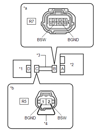
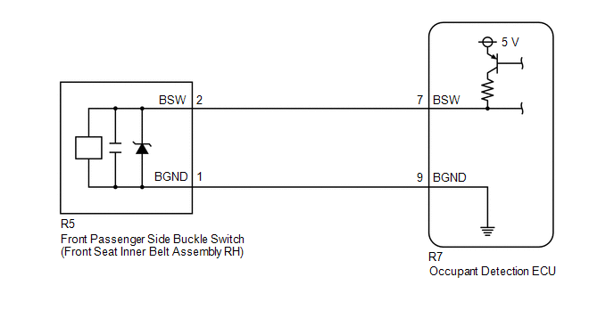
The front passenger side buckle switch circuit consists of the occupant detection ECU and front passenger side buckle switch (front seat inner belt assembly RH).
DTC B1771 is stored when a malfunction is detected in the front passenger side buckle switch circuit.
|
DTC No. | Detection Item |
DTC Detection Condition | Trouble Area |
|---|---|---|---|
|
B1771 | Passenger Side Buckle Switch Circuit Malfunction |
|
|
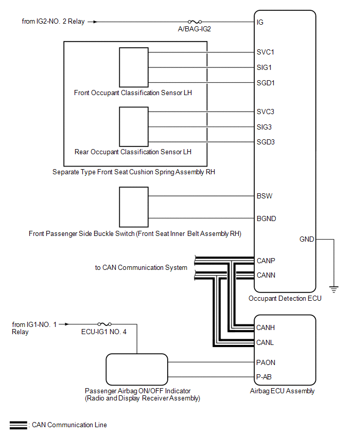
WIRING DIAGRAM
CAUTION / NOTICE / HINT
NOTICE:
After turning the power switch off, waiting time may be required before disconnecting the cable from the negative (-) auxiliary battery terminal. Therefore, make sure to read the disconnecting the cable from the negative (-) auxiliary battery terminal notices before proceeding with work.
Click here 
HINT:
PROCEDURE
|
1. | CHECK CONNECTORS |
(a) Turn the power switch off.
(b) Disconnect the cable from the negative (-) auxiliary battery terminal.
(c) Check that the connectors are properly connected to the occupant detection ECU and front seat inner belt assembly RH.
OK:
The connectors are properly connected.
HINT:
If the connectors are not properly connected, reconnect the connectors and proceed to the next inspection.
(d) Disconnect the connectors from the occupant detection ECU and front seat inner belt assembly RH.
(e) Check that the terminals of the connectors are not deformed or damaged.
OK:
The terminals are not deformed or damaged.
| NG |  | REPLACE FRONT SEAT WIRE RH |
|
| 2. |
CHECK FRONT SEAT WIRE RH |
| (a) Connect the cable to the negative (-) auxiliary battery terminal. |
|
(b) Turn the power switch on (IG).
(c) Measure the voltage according to the value(s) in the table below.
Standard Voltage:
|
Tester Connection | Condition |
Specified Condition |
|---|---|---|
|
R7-7 (BSW) - Body ground |
Power switch on (IG) |
Below 1 V |
| R7-9 (BGND) - Body ground |
Power switch on (IG) |
Below 1 V |
(d) Turn the power switch off.
(e) Disconnect the cable from the negative (-) auxiliary battery terminal.
(f) Using a service wire, connect terminals 2 (BSW) and 1 (BGND) of connector C.
NOTICE:
Do not forcibly insert the service wire into the terminals of the connector when connecting the wire.
(g) Measure the resistance according to the value(s) in the table below.
Standard Resistance:
|
Tester Connection | Condition |
Specified Condition |
|---|---|---|
|
R7-7 (BSW) - R7-9 (BGND) |
Always | Below 1 Ω |
(h) Disconnect the service wire from connector C.
(i) Measure the resistance according to the value(s) in the table below.
Standard Resistance:
|
Tester Connection | Condition |
Specified Condition |
|---|---|---|
|
R7-7 (BSW) - R7-9 (BGND) |
Always | 1 MΩ or higher |
|
R7-7 (BSW) - Body ground |
Always | 1 MΩ or higher |
|
R7-9 (BGND) - Body ground |
Always | 1 MΩ or higher |
| NG | | REPLACE FRONT SEAT WIRE RH |
|
| 3. |
CHECK DTC |
(a) Connect the connectors to the occupant detection ECU and front seat inner belt assembly RH.
(b) Connect the cable to the negative (-) auxiliary battery terminal.
(c) Turn the power switch on (IG), and wait for at least 60 seconds.
(d) Clear the DTCs stored in the occupant detection ECU.
Body Electrical > Occupant Detection > Clear DTCs(e) Clear the DTCs stored in the airbag ECU assembly.
Body Electrical > SRS Airbag > Clear DTCs(f) Turn the power switch off.
(g) Turn the power switch on (IG), and wait for at least 10 seconds.
(h) Check for DTCs.
Body Electrical > Occupant Detection > Trouble CodesOK:
DTC B1771 is not output.
HINT:
Codes other than DTC B1771 may be output at this time, but they are not related to this check.
(i) Turn the power switch off.
| OK | |
USE SIMULATION METHOD TO CHECK |
|
| 4. |
CHECK FRONT SEAT INNER BELT ASSEMBLY RH |
(a) Disconnect the cable from the negative (-) auxiliary battery terminal.
(b) Replace the front seat inner belt assembly RH with a known good one.
Click here
HINT:
Perform the following inspection using known good parts from another vehicle if possible.
(c) Connect the cable to the negative (-) auxiliary battery terminal.
(d) Turn the power switch on (IG), and wait for at least 60 seconds.
(e) Clear the DTCs stored in the occupant detection ECU.
Body Electrical > Occupant Detection > Clear DTCs(f) Clear the DTCs stored in the airbag ECU assembly.
Body Electrical > SRS Airbag > Clear DTCs(g) Turn the power switch off.
(h) Turn the power switch on (IG), and wait for at least 10 seconds.
(i) Check for DTCs.
Body Electrical > Occupant Detection > Trouble CodesOK:
DTC B1771 is not output.
HINT:
Codes other than DTC B1771 may be output at this time, but they are not related to this check.
(j) Turn the power switch off.
(k) Disconnect the cable from the negative (-) auxiliary battery terminal.
(l) Restore the front seat inner belt assembly RH that was installed for testing to its original location.
Click here
| OK | | REPLACE FRONT SEAT INNER BELT ASSEMBLY RH |
|
| 5. |
REPLACE OCCUPANT DETECTION ECU |
(a) Turn the power switch off.
(b) Disconnect the cable from the negative (-) auxiliary battery terminal.
(c) Replace the occupant detection ECU with a new one.
Click here
(d) Connect the cable to the negative (-) auxiliary battery terminal.
|
| 6. |
PERFORM ZERO POINT CALIBRATION |
(a) Using the Techstream, perform Zero Point Calibration.
Click here
| NEXT | | END |
DESCRIPTION
The front occupant classification sensor LH circuit consists of the occupant detection ECU and front occupant classification sensor LH.
DTC B1780 is stored when a malfunction is detected in the front occupant classification sensor LH circuit.
|
DTC No. | Detection Item |
DTC Detection Condition | Trouble Area |
|---|---|---|---|
|
B1780 | Front Occupant Classification Sensor LH Circuit Malfunction |
|
|
WIRING DIAGRAM

CAUTION / NOTICE / HINT
NOTICE:
After turning the power switch off, waiting time may be required before disconnecting the cable from the negative (-) auxiliary battery terminal. Therefore, make sure to read the disconnecting the cable from the negative (-) auxiliary battery terminal notices before proceeding with work.
Click here 
HINT:
PROCEDURE
|
1. | CHECK CONNECTORS |
(a) Turn the power switch off.
(b) Disconnect the cable from the negative (-) auxiliary battery terminal.
(c) Check that the connectors are properly connected to the occupant detection ECU and front occupant classification sensor LH.
OK:
The connectors are properly connected.
HINT:
If the connectors are not properly connected, reconnect the connectors and proceed to the next inspection.
(d) Disconnect the connectors from the occupant detection ECU and front occupant classification sensor LH.
(e) Check that the terminals of the connectors are not deformed or damaged.
OK:
The terminals are not deformed or damaged.
| NG | | REPLACE FRONT SEAT WIRE RH |
|
| 2. |
CHECK FRONT SEAT WIRE RH |
| (a) Connect the cable to the negative (-) auxiliary battery terminal. |
|
(b) Turn the power switch on (IG).
(c) Measure the voltage according to the value(s) in the table below.
Standard Voltage:
|
Tester Connection | Condition |
Specified Condition |
|---|---|---|
|
R8-1 (SVC1) - Body ground |
Power switch on (IG) |
Below 1 V |
| R8-3 (SIG1) - Body ground |
Power switch on (IG) |
Below 1 V |
|
R8-5 (SGD1) - Body ground |
Power switch on (IG) |
Below 1 V |
(d) Turn the power switch off.
(e) Disconnect the cable from the negative (-) auxiliary battery terminal.
(f) Using service wires, connect terminals 1 (SVC1) and 3 (SGD1), and terminals 2 (SIG1) and 3 (SGD1) of connector C.
NOTICE:
Do not forcibly insert the service wire into the terminals of the connector when connecting the wire.
(g) Measure the resistance according to the value(s) in the table below.
Standard Resistance:
|
Tester Connection | Condition |
Specified Condition |
|---|---|---|
|
R8-1 (SVC1) - R8-5 (SGD1) |
Always | Below 1 Ω |
|
R8-3 (SIG1) - R8-5 (SGD1) |
Always | Below 1 Ω |
(h) Disconnect the service wires from connector C.
(i) Measure the resistance according to the value(s) in the table below.
Standard Resistance:
|
Tester Connection | Condition |
Specified Condition |
|---|---|---|
|
R8-1 (SVC1) - R8-5 (SGD1) |
Always | 1 MΩ or higher |
|
R8-3 (SIG1) - R8-5 (SGD1) |
Always | 1 MΩ or higher |
|
R8-1 (SVC1) - R8-3 (SIG1) |
Always | 1 MΩ or higher |
|
R8-1 (SVC1) - Body ground |
Always | 1 MΩ or higher |
|
R8-3 (SIG1) - Body ground |
Always | 1 MΩ or higher |
|
R8-5 (SGD1) - Body ground |
Always | 1 MΩ or higher |
| NG | | REPLACE FRONT SEAT WIRE RH |
|
| 3. |
CHECK DTC |
(a) Connect the connectors to the occupant detection ECU and front occupant classification sensor LH.
(b) Connect the cable to the negative (-) auxiliary battery terminal.
(c) Turn the power switch on (IG), and wait for at least 60 seconds.
(d) Clear the DTCs stored in the occupant detection ECU.
Body Electrical > Occupant Detection > Clear DTCs(e) Clear the DTCs stored in the airbag ECU assembly.
Body Electrical > SRS Airbag > Clear DTCs(f) Turn the power switch off.
(g) Turn the power switch on (IG), and wait for at least 10 seconds.
(h) Check for DTCs.
Body Electrical > Occupant Detection > Trouble CodesOK:
DTC B1780 is not output.
HINT:
Codes other than DTC B1780 may be output at this time, but they are not related to this check.
(i) Turn the power switch off.
| OK | |
USE SIMULATION METHOD TO CHECK |
|
| 4. |
CHECK OCCUPANT DETECTION ECU |
(a) Disconnect the cable from the negative (-) auxiliary battery terminal.
(b) Replace the occupant detection ECU with a known good one.
Click here
HINT:
Perform the following inspection using known good parts from another vehicle if possible.
(c) Connect the cable to the negative (-) auxiliary battery terminal.
(d) Turn the power switch on (IG), and wait for at least 60 seconds.
(e) Clear the DTCs stored in the occupant detection ECU.
Body Electrical > Occupant Detection > Clear DTCs(f) Clear the DTCs stored in the airbag ECU assembly.
Body Electrical > SRS Airbag > Clear DTCs(g) Turn the power switch off.
(h) Turn the power switch on (IG), and wait for at least 10 seconds.
(i) Check for DTCs.
Body Electrical > Occupant Detection > Trouble CodesOK:
DTC B1780 is not output.
HINT:
Codes other than DTC B1780 may be output at this time, but they are not related to this check.
(j) Turn the power switch off.
(k) Disconnect the cable from the negative (-) auxiliary battery terminal.
(l) Restore the occupant detection ECU that was installed for testing to its original location.
Click here
| NG | | GO TO STEP 7 |
|
| 5. |
REPLACE OCCUPANT DETECTION ECU |
(a) Turn the power switch off.
(b) Disconnect the cable from the negative (-) auxiliary battery terminal.
(c) Replace the occupant detection ECU with a new one.
Click here
(d) Connect the cable to the negative (-) auxiliary battery terminal.
|
| 6. |
PERFORM ZERO POINT CALIBRATION |
(a) Using the Techstream, perform Zero Point Calibration.
Click here
| NEXT | | END |
| 7. |
REPLACE SEPARATE TYPE FRONT SEAT CUSHION SPRING ASSEMBLY RH |
(a) Turn the power switch off.
(b) Disconnect the cable from the negative (-) auxiliary battery terminal.
(c) Replace the separate type front seat cushion spring assembly RH.
Click here
(d) Connect the cable to the negative (-) auxiliary battery terminal.
|
| 8. |
PERFORM ZERO POINT CALIBRATION |
(a) Using the Techstream, perform Zero Point Calibration.
Click here
| NEXT | | END |
DESCRIPTION
The rear occupant classification sensor LH circuit consists of the occupant detection ECU and rear occupant classification sensor LH.
DTC B1782 is stored when a malfunction is detected in the rear occupant classification sensor LH circuit.
|
DTC No. | Detection Item |
DTC Detection Condition | Trouble Area |
|---|---|---|---|
|
B1782 | Rear Occupant Classification Sensor LH Circuit Malfunction |
|
|
WIRING DIAGRAM

CAUTION / NOTICE / HINT
NOTICE:
After turning the power switch off, waiting time may be required before disconnecting the cable from the negative (-) auxiliary battery terminal. Therefore, make sure to read the disconnecting the cable from the negative (-) auxiliary battery terminal notices before proceeding with work.
Click here 
HINT:
PROCEDURE
|
1. | CHECK CONNECTORS |
(a) Turn the power switch off.
(b) Disconnect the cable from the negative (-) auxiliary battery terminal.
(c) Check that the connectors are properly connected to the occupant detection ECU and rear occupant classification sensor LH.
OK:
The connectors are properly connected.
HINT:
If the connectors are not properly connected, reconnect the connectors and proceed to the next inspection.
(d) Disconnect the connectors from the occupant detection ECU and rear occupant classification sensor LH.
(e) Check that the terminals of the connectors are not deformed or damaged.
OK:
The terminals are not deformed or damaged.
| NG |  | REPLACE FRONT SEAT WIRE RH |
|
| 2. |
CHECK FRONT SEAT WIRE RH |
| (a) Connect the cable to the negative (-) auxiliary battery terminal. |
|
(b) Turn the power switch on (IG).
(c) Measure the voltage according to the value(s) in the table below.
Standard Voltage:
|
Tester Connection | Condition |
Specified Condition |
|---|---|---|
|
R8-2 (SVC3) - Body ground |
Power switch on (IG) |
Below 1 V |
| R8-4 (SIG3) - Body ground |
Power switch on (IG) |
Below 1 V |
|
R8-6 (SGD3) - Body ground |
Power switch on (IG) |
Below 1 V |
(d) Turn the power switch off.
(e) Disconnect the cable from the negative (-) auxiliary battery terminal.
(f) Using service wires, connect terminals 1 (SVC3) and 3 (SGD3), and terminals 2 (SIG3) and 3 (SGD3) of connector C.
NOTICE:
Do not forcibly insert the service wire into the terminals of the connector when connecting the wire.
(g) Measure the resistance according to the value(s) in the table below.
Standard Resistance:
|
Tester Connection | Condition |
Specified Condition |
|---|---|---|
|
R8-2 (SVC3) - R8-6 (SGD3) |
Always | Below 1 Ω |
|
R8-4 (SIG3) - R8-6 (SGD3) |
Always | Below 1 Ω |
(h) Disconnect the service wires from connector C.
(i) Measure the resistance according to the value(s) in the table below.
Standard Resistance:
|
Tester Connection | Condition |
Specified Condition |
|---|---|---|
|
R8-2 (SVC3) - R8-6 (SGD3) |
Always | 1 MΩ or higher |
|
R8-4 (SIG3) - R8-6 (SGD3) |
Always | 1 MΩ or higher |
|
R8-2 (SVC3) - R8-4 (SIG3) |
Always | 1 MΩ or higher |
|
R8-2 (SVC3) - Body ground |
Always | 1 MΩ or higher |
|
R8-4 (SIG3) - Body ground |
Always | 1 MΩ or higher |
|
R8-6 (SGD3) - Body ground |
Always | 1 MΩ or higher |
| NG | | REPLACE FRONT SEAT WIRE RH |
|
| 3. |
CHECK DTC |
(a) Connect the connectors to the occupant detection ECU and rear occupant classification sensor LH.
(b) Connect the cable to the negative (-) auxiliary battery terminal.
(c) Turn the power switch on (IG), and wait for at least 60 seconds.
(d) Clear the DTCs stored in the occupant detection ECU.
Body Electrical > Occupant Detection > Clear DTCs(e) Clear the DTCs stored in the airbag ECU assembly.
Body Electrical > SRS Airbag > Clear DTCs(f) Turn the power switch off.
(g) Turn the power switch on (IG), and wait for at least 10 seconds.
(h) Check for DTCs.
Body Electrical > Occupant Detection > Trouble CodesOK:
DTC B1782 is not output.
HINT:
Codes other than DTC B1782 may be output at this time, but they are not related to this check.
(i) Turn the power switch off.
| OK | |
USE SIMULATION METHOD TO CHECK |
|
| 4. |
CHECK OCCUPANT DETECTION ECU |
(a) Disconnect the cable from the negative (-) auxiliary battery terminal.
(b) Replace the occupant detection ECU with a known good one.
Click here
HINT:
Perform the following inspection using known good parts from another vehicle if possible.
(c) Connect the cable to the negative (-) auxiliary battery terminal.
(d) Turn the power switch on (IG), and wait for at least 60 seconds.
(e) Clear the DTCs stored in the occupant detection ECU.
Body Electrical > Occupant Detection > Clear DTCs(f) Clear the DTCs stored in the airbag ECU assembly.
Body Electrical > SRS Airbag > Clear DTCs(g) Turn the power switch off.
(h) Turn the power switch on (IG), and wait for at least 10 seconds.
(i) Check for DTCs.
Body Electrical > Occupant Detection > Trouble CodesOK:
DTC B1782 is not output.
HINT:
Codes other than DTC B1782 may be output at this time, but they are not related to this check.
(j) Turn the power switch off.
(k) Disconnect the cable from the negative (-) auxiliary battery terminal.
(l) Restore the occupant detection ECU that was installed for testing to its original location.
Click here
| NG | | GO TO STEP 7 |
|
| 5. |
REPLACE OCCUPANT DETECTION ECU |
(a) Turn the power switch off.
(b) Disconnect the cable from the negative (-) auxiliary battery terminal.
(c) Replace the occupant detection ECU with a new one.
Click here
(d) Connect the cable to the negative (-) auxiliary battery terminal.
|
| 6. |
PERFORM ZERO POINT CALIBRATION |
(a) Using the Techstream, perform Zero Point Calibration.
Click here
| NEXT | | END |
| 7. |
REPLACE SEPARATE TYPE FRONT SEAT CUSHION SPRING ASSEMBLY RH |
(a) Turn the power switch off.
(b) Disconnect the cable from the negative (-) auxiliary battery terminal.
(c) Replace the separate type front seat cushion spring assembly RH.
Click here
(d) Connect the cable to the negative (-) auxiliary battery terminal.
|
| 8. |
PERFORM ZERO POINT CALIBRATION |
(a) Using the Techstream, perform Zero Point Calibration.
Click here
| NEXT | | END |
DESCRIPTION
DTC B1785 is stored when the occupant detection ECU receives a collision detection signal sent by the front occupant classification sensor LH in the case of an accident.
DTC B1785 is also stored when the front seat assembly RH is subjected to a strong impact, even if an actual accident did not occur.
If the vehicle was not in a collision, but the occupant detection ECU receives a collision detection signal and stores DTC B1785, the DTC can be cleared by performing zero point calibration. Therefore, if DTC B1785 is output, first perform zero point calibration.
|
DTC No. | Detection Item |
DTC Detection Condition | Trouble Area |
|---|---|---|---|
|
B1785 | Front Occupant Classification Sensor LH Collision Detection |
| Front occupant classification sensor LH (Separate type front seat cushion spring assembly RH)* |
CAUTION / NOTICE / HINT
NOTICE:
If the occupant detection ECU is replaced, this DTC will not be output but the occupant detection system may not function properly.
Click here 
HINT:
When DTC B165A is stored as a result of troubleshooting for the airbag system, check the DTCs stored in the occupant detection ECU. When DTC B1785 is output, perform troubleshooting for this DTC first.
PROCEDURE
| 1. |
PERFORM ZERO POINT CALIBRATION |
(a) Using the Techstream, perform Zero Point Calibration.
Click here
OK:
"Zero Point Calibration is complete." is displayed.
| NG | | GO TO STEP 5 |
|
| 2. |
CHECK DTC |
(a) Turn the power switch on (IG), and wait for at least 60 seconds.
(b) Clear the DTCs stored in the occupant detection ECU.
Body Electrical > Occupant Detection > Clear DTCs(c) Clear the DTCs stored in the airbag ECU assembly.
Body Electrical > SRS Airbag > Clear DTCs(d) Turn the power switch off.
(e) Turn the power switch on (IG), and wait for at least 10 seconds.
(f) Check for DTCs.
Body Electrical > Occupant Detection > Trouble CodesOK:
DTC B1785 is not output.
HINT:
Codes other than DTC B1785 may be output at this time, but they are not related to this check.
(g) Turn the power switch off.
| OK | |
END |
|
| 3. |
REPLACE SEPARATE TYPE FRONT SEAT CUSHION SPRING ASSEMBLY RH |
(a) Turn the power switch off.
(b) Disconnect the cable from the negative (-) auxiliary battery terminal.
(c) Replace the separate type front seat cushion spring assembly RH.
Click here
(d) Connect the cable to the negative (-) auxiliary battery terminal.
|
| 4. |
PERFORM ZERO POINT CALIBRATION |
(a) Using the Techstream, perform Zero Point Calibration.
Click here
| NEXT | | END |
| 5. |
REPLACE SEPARATE TYPE FRONT SEAT CUSHION SPRING ASSEMBLY RH |
(a) Turn the power switch off.
(b) Disconnect the cable from the negative (-) auxiliary battery terminal.
(c) Replace the separate type front seat cushion spring assembly RH.
Click here
(d) Connect the cable to the negative (-) auxiliary battery terminal.
|
| 6. |
PERFORM ZERO POINT CALIBRATION |
(a) Using the Techstream, perform Zero Point Calibration.
Click here
| NEXT | | END |
DESCRIPTION
DTC B1787 is stored when the occupant detection ECU receives a collision detection signal sent by the rear occupant classification sensor LH in the case of an accident.
DTC B1787 is also stored when the front seat assembly RH is subjected to a strong impact, even if an actual accident did not occur.
If the vehicle was not in a collision, but the occupant detection ECU receives a collision detection signal and stores DTC B1787, the DTC can be cleared by performing zero point calibration. Therefore, if DTC B1787 is output, first perform zero point calibration.
|
DTC No. | Detection Item |
DTC Detection Condition | Trouble Area |
|---|---|---|---|
|
B1787 | Rear Occupant Classification Sensor LH Collision Detection |
| Rear occupant classification sensor LH (Separate type front seat cushion spring assembly RH)* |
CAUTION / NOTICE / HINT
NOTICE:
If the occupant detection ECU is replaced, this DTC will not be output but the occupant detection system may not function properly.
Click here 
HINT:
When DTC B165A is stored as a result of troubleshooting for the airbag system, check the DTCs stored in the occupant detection ECU. When DTC B1787 is output, perform troubleshooting for this DTC first.
PROCEDURE
| 1. |
PERFORM ZERO POINT CALIBRATION |
(a) Using the Techstream, perform Zero Point Calibration.
Click here
OK:
"Zero Point Calibration is complete." is displayed.
| NG |  | GO TO STEP 5 |
|
| 2. |
CHECK DTC |
(a) Turn the power switch on (IG), and wait for at least 60 seconds.
(b) Clear the DTCs stored in the occupant detection ECU.
Body Electrical > Occupant Detection > Clear DTCs(c) Clear the DTCs stored in the airbag ECU assembly.
Body Electrical > SRS Airbag > Clear DTCs(d) Turn the power switch off.
(e) Turn the power switch on (IG), and wait for at least 10 seconds.
(f) Check for DTCs.
Body Electrical > Occupant Detection > Trouble CodesOK:
DTC B1787 is not output.
HINT:
Codes other than DTC B1787 may be output at this time, but they are not related to this check.
(g) Turn the power switch off.
| OK | |
END |
|
| 3. |
REPLACE SEPARATE TYPE FRONT SEAT CUSHION SPRING ASSEMBLY RH |
(a) Turn the power switch off.
(b) Disconnect the cable from the negative (-) auxiliary battery terminal.
(c) Replace the separate type front seat cushion spring assembly RH.
Click here
(d) Connect the cable to the negative (-) auxiliary battery terminal.
|
| 4. |
PERFORM ZERO POINT CALIBRATION |
(a) Using the Techstream, perform Zero Point Calibration.
Click here
| NEXT | | END |
| 5. |
REPLACE SEPARATE TYPE FRONT SEAT CUSHION SPRING ASSEMBLY RH |
(a) Turn the power switch off.
(b) Disconnect the cable from the negative (-) auxiliary battery terminal.
(c) Replace the separate type front seat cushion spring assembly RH.
Click here
(d) Connect the cable to the negative (-) auxiliary battery terminal.
|
| 6. |
PERFORM ZERO POINT CALIBRATION |
(a) Using the Techstream, perform Zero Point Calibration.
Click here
| NEXT | | END |
DESCRIPTION
DTC B1795 is stored when a malfunction is detected in the occupant detection ECU.
|
DTC No. | Detection Item |
DTC Detection Condition | Trouble Area |
|---|---|---|---|
|
B1795 | Occupant Classification ECU Malfunction |
Occupant detection ECU malfunction |
Occupant detection ECU |
CAUTION / NOTICE / HINT
NOTICE:
After turning the power switch off, waiting time may be required before disconnecting the cable from the negative (-) auxiliary battery terminal. Therefore, make sure to read the disconnecting the cable from the negative (-) auxiliary battery terminal notices before proceeding with work.
Click here 
HINT:
When DTC B1650 is stored as a result of troubleshooting for the airbag system, check the DTCs stored in the occupant detection ECU. When DTC B1795 is output, perform troubleshooting for this DTC first.
PROCEDURE
| 1. |
CHECK DTC |
(a) Turn the power switch on (IG), and wait for at least 60 seconds.
(b) Clear the DTCs stored in the occupant detection ECU.
Body Electrical > Occupant Detection > Clear DTCs(c) Clear the DTCs stored in the airbag ECU assembly.
Body Electrical > SRS Airbag > Clear DTCs(d) Turn the power switch off.
(e) Turn the power switch on (IG), and wait for at least 10 seconds.
(f) Check for DTCs.
Body Electrical > Occupant Detection > Trouble CodesOK:
DTC B1795 is not output.
HINT:
Codes other than DTC B1795 may be output at this time, but they are not related to this check.
(g) Turn the power switch off.
| OK |  |
USE SIMULATION METHOD TO CHECK |
|
| 2. |
REPLACE OCCUPANT DETECTION ECU |
(a) Turn the power switch off.
(b) Disconnect the cable from the negative (-) auxiliary battery terminal.
(c) Replace the occupant detection ECU with a new one.
Click here
(d) Connect the cable to the negative (-) auxiliary battery terminal.
|
| 3. |
PERFORM ZERO POINT CALIBRATION |
(a) Using the Techstream, perform Zero Point Calibration.
Click here
| NEXT | | END |
DESCRIPTION
The occupant detection ECU receives signals from the acceleration sensor (airbag ECU assembly) and skid control ECU (brake booster with master cylinder assembly) via CAN communication.
|
DTC No. | Detection Item |
DTC Detection Condition | Trouble Area |
|---|---|---|---|
|
B1798 | Yaw Rate Sensor Module Malfunction |
Acceleration signals are abnormal |
|
| B1799 |
Vehicle Stability Control ECU Malfunction |
Vehicle speed signal from skid control ECU is abnormal |
|
CAUTION / NOTICE / HINT
NOTICE:
After turning the power switch off, waiting time may be required before disconnecting the cable from the negative (-) auxiliary battery terminal. Therefore, make sure to read the disconnecting the cable from the negative (-) auxiliary battery terminal notices before proceeding with work.
Click here 
HINT:
PROCEDURE
|
1. | CHECK DTC (ELECTRONICALLY CONTROLLED BRAKE SYSTEM) |
(a) Check for electronically controlled brake system DTCs.
Click here
OK:
DTCs are not output.
| NG |  | GO TO ELECTRONICALLY CONTROLLED BRAKE SYSTEM |
|
| 2. |
CHECK CAN COMMUNICATION SYSTEM |
(a) Using the Techstream, check if the CAN communication system is functioning normally.
OK:
CAN communication system is functioning normally.
HINT:
Refer to Communication Bus Check in CAN Communication System.
Click here
| NG | |
GO TO CAN COMMUNICATION SYSTEM |
|
| 3. |
CHECK DTC (HEALTH CHECK) |
(a) Turn the power switch off.
(b) Connect the Techstream to the DLC3.
(c) Turn the power switch on (IG) and turn the Techstream on.
(d) Enter the following menus: System Select / Health Check.
OK:
DTCs are not output.
| OK | |
USE SIMULATION METHOD TO CHECK |
| NG | | GO TO OTHER DIAGNOSTIC TROUBLE CODE CHART |
DATA LIST / ACTIVE TEST
DATA LIST
HINT:
Using the Techstream to read the Data List allows the values or states of switches, sensors, actuators and other items to be read without removing any parts. This non-intrusive inspection can be very useful because intermittent conditions or signals may be discovered before parts or wiring is disturbed. Reading the Data List information early in troubleshooting is one way to save diagnostic time.
NOTICE:
In the table below, the values listed under "Normal Condition" are reference values. Do not depend solely on these reference values when deciding whether a part is faulty or not.
(a) Turn the power switch off.
(b) Connect the Techstream to the DLC3.
(c) Turn the power switch on (IG).
(d) Turn the Techstream on.
(e) Enter the following menus: Body Electrical / Occupant Detection / Data List.
(f) Read the Data List according to the display on the Techstream.
Body Electrical > Occupant Detection > Data List|
Tester Display | Measurement Item |
Range | Normal Condition |
Diagnostic Note |
|---|---|---|---|---|
|
FL Sensor Weight Information |
Front left sensor weight information |
Min.: -75.852 kg (-167.223 lb) Max.: 104.737 kg (230.903 lb) |
Current value displayed |
- |
| RL Sensor Weight Information |
Rear left sensor weight information |
Min.: -75.852 kg (-167.223 lb) Max.: 104.737 kg (230.903 lb) |
Current value displayed |
- |
| Total Weight Information |
Total weight information |
Min.: -151.704 kg (-334.446 lb) Max.: 209.475 kg (461.808 lb) |
Current value displayed |
- |
| Weight Forward and Rearward Difference |
Weight difference between front and rear |
Min.: -180.589 kg (-398.126 lb) Max.: 180.589 kg (398.126 lb) |
Current value displayed |
- |
| Airbag Total Weight |
Total weight information for airbag system |
Min.: -161.595 kg (-356.252 lb) Max.: 226.017 kg (498.277 lb) |
Current value displayed |
- |
| Belt Warning Total Weight |
Total weight information for seat belt warning system |
Min.: -155.001 kg (-341.715 lb) Max.: 219.400 kg (483.689 lb) |
Current value displayed |
- |
| VSC Status |
Vehicle speed status | ON or OFF |
ON: Vehicle speed valid |
- |
| VSC Vehicle Speed |
Vehicle speed | Min.: 0.00 km/h (0.00 mph) Max.: 327.67 km/h (203.61 mph) |
Current value displayed |
- |
| VSC Zero Point1 |
Zero point for acceleration sensor 1 |
Min.: -4.5952 m/s2 Max.: 4.5593 m/s2 |
Current value displayed |
- |
| VSC Zero Point2 |
Zero point for acceleration sensor 2 |
Min.: -4.5952 m/s2 Max.: 4.5593 m/s2 |
Current value displayed |
- |
| VSC Calibration Status |
Vehicle stability control calibration status |
Calibrated or Uncalibrated |
Calibrated | - |
|
VSC Assembly Information |
Acceleration sensor information |
Reverse Position or Normal Position |
Reverse Position or Normal Position |
Displays a fixed value for each vehicle. |
|
Yaw Rate/G Sensor Voltage Invalid Flag |
Yaw rate and acceleration sensor voltage invalid flag |
ON or OFF | ON: Valid |
- |
| Yaw Rate/G Sensor Malfunction Flag1 |
Malfunction flag for acceleration sensor 1 |
OK or NG | OK |
- |
| Yaw Rate/G Sensor Invalid Flag1 |
Invalid flag for acceleration sensor 1 |
ON or OFF | ON: Valid |
- |
| Yaw Rate/G Sensor Malfunction Flag2 |
Malfunction flag for acceleration sensor 2 |
OK or NG | OK |
- |
| Yaw Rate/G Sensor Invalid Flag2 |
Invalid flag for acceleration sensor 2 |
ON or OFF | ON: Valid |
- |
| Yaw Rate/G Sensor Assembly Information |
Acceleration sensor information for occupant classification system |
Unset, Reverse Position or Normal Position |
Reverse Position or Normal Position |
|
| Passenger Detection(Airbag) |
Front passenger classification |
OFF/Child, CRS1, CRS2, AF05 or AM50 |
OFF/Child: Vacant or child is seated CRS1: Child restraint system is installed CRS2: Child restraint system is installed AF05: Adult is seated AM50: Adult is seated |
- |
| Passenger Detection(Belt Warning) |
Front passenger detection for seat belt warning system |
OFF, Baggage or ON | OFF: Seat is vacant Baggage: Seat is occupied by baggage ON: Seat is occupied |
- |
| Driving Status |
Driving status | Stop, Drive or Turn |
Stop: Vehicle is stopped Drive: Vehicle is being driven straight Turn: Vehicle is turning |
- |
| Passenger Buckle SW |
Front passenger side buckle switch |
NG, Set or Unset | Set: Front passenger seat belt is fastened Unset: Front passenger seat belt is not fastened |
"NG" will be displayed immediately after the power switch is turned on (IG). |
|
The Number of DTCs | Number of DTC recorded |
Min.: 0, Max.: 255 | 0 |
The number displayed is the total current DTCs and history DTCs stored (excluding duplicates). |
DIAGNOSIS SYSTEM
CHECK DLC3
(a) Check the DLC3.
Click here 
FUNCTION OF PASSENGER AIRBAG ON/OFF INDICATOR
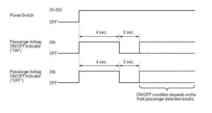
(a) Initial check
(1) Turn the power switch on (IG).
(2) The passenger airbag ON/OFF indicator comes on for approximately 4 seconds, then turns off for approximately 2 seconds.
(3) Approximately 6 seconds after the power switch is turned on (IG), the passenger airbag ON/OFF indicator will indicate ON/OFF depending on the following conditions.
Indicator Operation|
Front Passenger Seat Condition |
Passenger Airbag ON/OFF Indicator |
SRS Warning Light | |
|---|---|---|---|
|
ON Indicator | OFF Indicator | ||
|
Vacant | OFF |
ON | OFF |
|
Adult*1 is seated | ON |
OFF | OFF |
|
Child*2 is seated | ON or OFF*2 |
OFF or ON*2 | OFF |
|
Child restraint system is installed |
OFF | ON |
OFF |
| Occupant classification system failure |
OFF | ON |
ON |
HINT:
PASSENGER AIRBAG ON/OFF INDICATOR CHECK
(a) Turn the power switch on (IG).
(b) Check that the passenger airbag ON/OFF indicator ("ON" and "OFF") comes on for approximately 4 seconds, then turns off for approximately 2 seconds.
HINT:
Refer to the indicator operation table in Function of Passenger Airbag ON/OFF Indicator for the passenger airbag ON/OFF indicator operation when the power switch is turned on (IG) and approximately 6 seconds elapse.
DIAGNOSTIC TROUBLE CODE CHART
Occupant Classification System|
DTC No. | Detection Item |
Link |
|---|---|---|
| B1771 |
Passenger Side Buckle Switch Circuit Malfunction |
|
|
B1780 | Front Occupant Classification Sensor LH Circuit Malfunction |
|
|
B1782 | Rear Occupant Classification Sensor LH Circuit Malfunction |
|
|
B1785 | Front Occupant Classification Sensor LH Collision Detection |
|
|
B1787 | Rear Occupant Classification Sensor LH Collision Detection |
|
|
B1795 | Occupant Classification ECU Malfunction |
|
|
B1798 | Yaw Rate Sensor Module Malfunction |
|
|
B1799 | Vehicle Stability Control ECU Malfunction |
|
|
U0125 | Lost Communication with Multi-axis Acceleration Sensor Module |
|
|
U0129 | Lost Communication with Brake System Control Module |
|
DTC CHECK / CLEAR
DTC CHECK
(a) Turn the power switch off.
(b) Connect the Techstream to the DLC3.
(c) Turn the power switch on (IG), and wait for at least 10 seconds.
(d) Turn the Techstream on.
(e) Enter the following menus: Body Electrical / Occupant Detection / Trouble Codes.
Body Electrical > Occupant Detection > Trouble Codes(f) Check for DTCs by following the prompts on the Techstream screen.
HINT:
Refer to the Techstream operator's manual for further details.
DTC CLEAR
(a) Turn the power switch off.
(b) Connect the Techstream to the DLC3.
(c) Turn the power switch on (IG), and wait for at least 10 seconds.
(d) Turn the Techstream on.
(e) Enter the following menus: Body Electrical / Occupant Detection / Trouble Codes.
Body Electrical > Occupant Detection > Clear DTCs(f) Clear the DTCs by following the prompts on the Techstream screen.
HINT:
Refer to the Techstream operator's manual for further details.
FAIL-SAFE CHART
FAIL-SAFE FUNCTION
(a) The following chart shows the status of the front passenger SRS items and passenger airbag ON/OFF indicator operation under each condition.
|
Condition | Passenger Airbag ON/OFF Indicator |
Front Passenger SRS Item | |||||
|---|---|---|---|---|---|---|---|
|
ON Indicator | OFF Indicator |
Instrument Panel Passenger Airbag Assembly |
Lower No. 2 Instrument Panel Airbag Assembly |
Front Seat Airbag Assembly RH |
Curtain Shield Airbag Assembly RH |
Front Seat Outer Belt Assembly RH | |
|
○: Deployable
X: Not deployable *1: The system judges a person of average adult weight or more as an adult. If a smaller adult sits in the front passenger seat, the system may not recognize them as an adult depending on their physique and posture. *2: The system may not recognize a child or a child in a child restrain system as a child depending on factors such as the positioning of the child restraint system or the child's physique or posture. | |||||||
|
Adult*1 is seated | ON |
OFF | ○ |
○ | ○ |
○ | ○ |
|
Child*2 is seated | ON or OFF*2 |
OFF or ON*2 | ○ or X*2 |
○ or X*2 | ○ |
○ | ○ |
|
Child restraint system is installed |
OFF | ON |
X | X |
○ | ○ |
○ |
| Vacant |
OFF | ON |
X | X |
○ | ○ |
○ |
| Failure |
OFF | ON |
X | X |
○ | ○ |
○ |
CAUTION / NOTICE / HINT
HINT:
PROCEDURE
|
1. | VEHICLE BROUGHT TO WORKSHOP |
|
| 2. |
CUSTOMER PROBLEM ANALYSIS |
(a) Confirm problem symptoms.
Click here 
|
| 3. |
CHECK CAN COMMUNICATION SYSTEM* |
(a) Using the Techstream, check if the CAN communication system is functioning normally.
OK:
CAN communication system is functioning normally.
HINT:
Click here
| NG |  | GO TO CAN COMMUNICATION SYSTEM |
|
| 4. |
PASSENGER AIRBAG ON/OFF INDICATOR CHECK |
(a) Refer to Diagnosis System.
Click here
|
| 5. |
DTC CHECK (Present and History DTCs)* |
(a) Refer to DTC Check / Clear.
Click here
OK:
DTCs are not output.
| OK | | GO TO PROBLEM SYMPTOMS TABLE |
|
| 6. |
DIAGNOSTIC TROUBLE CODE CHART |
(a) Refer to Diagnostic Trouble Code Chart.
Click here
|
| 7. |
CIRCUIT INSPECTION* |
|
| 8. |
REPAIR |
|
| 9. |
CLEAR DTCS (Present and History DTCs)* |
(a) Refer to DTC Check / Clear.
Click here
|
| 10. |
DTC CHECK* |
(a) Refer to DTC Check / Clear.
Click here
OK:
DTCs are not output.
| NG | | GO TO STEP 6 |
|
| 11. |
SYMPTOM SIMULATION |
(a) Check the passenger airbag ON/OFF indicator condition.
|
| 12. |
CONFIRMATION TEST |
| NEXT | | END |
INITIALIZATION
DESCRIPTION
(a) Zero point of the occupant classification sensors may deviate in the following situations. To ensure sensor accuracy, be sure to perform Zero Point Calibration.
HINT:
As the zero point is not automatically stored in a new occupant detection ECU, it is necessary to perform zero point calibration after replacing the occupant detection ECU.
HINT:
As the weight of accessories will be added to the weight of the occupant, the system will not be able to perform classification accurately.
HINT:
As the seat frame will warp slightly when the bolts that are used to install the front passenger seat are tightened, the load applied to the occupant classification sensors will change and the system will not be able to perform classification accurately.
HINT:
As the seat frame will warp slightly when the bolts that are used to install the front passenger seat are tightened, the load applied to the occupant classification sensors will change and the system will not be able to perform classification accurately.
HINT:
If any load or pressure is applied to the occupant classification sensors, the system will not be able to perform classification accurately.
NOTICE:
Make sure that the front passenger seat is not occupied before performing the operation.
ZERO POINT CALIBRATION
(a) Zero point calibration procedure
(1) Check that all of the following conditions are met:
(2) Adjust the seat position according to the table below.
|
Adjustment Item | Position |
|---|---|
|
Slide Direction | 50 mm (1.97 in.) from rearmost position |
|
Headrest Height | Lowest position |
|
Recline Angle | Upright position |
|
Front Tilt Height | Lowest position |
|
Seat Lifter Height | Lowest position |
(3) Turn the power switch off.
(4) Connect the Techstream to the DLC3.
(5) Turn the power switch on (IG).
(6) Turn the Techstream on.
(7) Enter the following menus: Body Electrical / Occupant Detection / Utility / Zero Point Calibration.
Body Electrical > Occupant Detection > Utility|
Tester Display |
|---|
| Zero Point Calibration |
(8) Perform zero point calibration by following the prompts on the Techstream screen.
OK:
"Zero Point Calibration is complete." is displayed.
HINT:
PARTS LOCATION
ILLUSTRATION
|
*1 | BRAKE BOOSTER WITH MASTER CYLINDER ASSEMBLY - SKID CONTROL ECU | - |
- |
ILLUSTRATION
|
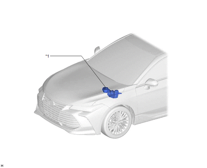
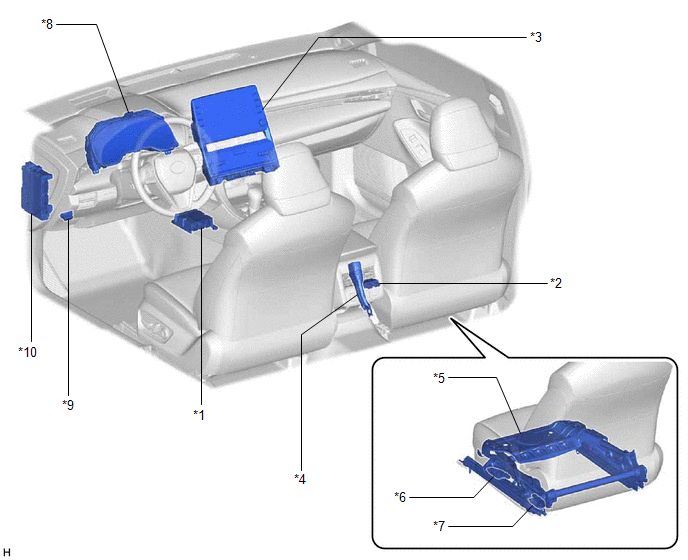
*1 | - ACCELERATION SENSOR AIRBAG ECU ASSEMBLY | *2 |
OCCUPANT DETECTION ECU |
|
*3 | RADIO AND DISPLAY RECEIVER ASSEMBLY - PASSENGER AIRBAG ON/OFF INDICATOR |
*4 | FRONT SEAT INNER BELT ASSEMBLY RH - FRONT PASSENGER SIDE BUCKLE SWITCH |
|
*5 | SEPARATE TYPE FRONT SEAT CUSHION SPRING ASSEMBLY RH |
*6 | FRONT OCCUPANT CLASSIFICATION SENSOR LH |
|
*7 | REAR OCCUPANT CLASSIFICATION SENSOR LH |
*8 | COMBINATION METER ASSEMBLY - SRS WARNING LIGHT |
|
*9 | DLC3 |
*10 | INSTRUMENT PANEL JUNCTION BLOCK ASSEMBLY - A/BAG-IG2 FUSE - ECU-IG1 NO. 4 FUSE |
PRECAUTION
PRECAUTION FOR DISCONNECTING CABLE FROM NEGATIVE AUXILIARY BATTERY TERMINAL
NOTICE:
When disconnecting the cable from the negative (-) auxiliary battery terminal, initialize the following systems after the cable is reconnected:
|
System | See Procedure |
|---|---|
|
Lane Departure Alert System (w/ Steering Control) |
|
|
Intelligent Clearance Sonar System | |
|
Parking Assist Monitor System | |
|
Panoramic View Monitor System | |
|
Pre-collision System | |
|
Lighting System (for HV Model with Cornering Light) |
GENERAL PRECAUTION
(a) The following conditions may be interpreted as a malfunction even though they are normal operation:
(b) Zero point of the occupant classification sensors may deviate in the following situations. To ensure sensor accuracy, be sure to perform Zero Point Calibration.
HINT:
As the zero point is not automatically stored in a new occupant detection ECU, it is necessary to perform zero point calibration after replacing the occupant detection ECU.
HINT:
As the weight of accessories will be added to the weight of the occupant, the system will not be able to perform classification accurately.
HINT:
As the seat frame will warp slightly when the bolts that are used to install the front passenger seat are tightened, the load applied to the occupant classification sensors will change and the system will not be able to perform classification accurately.
HINT:
As the seat frame will warp slightly when the bolts that are used to install the front passenger seat are tightened, the load applied to the occupant classification sensors will change and the system will not be able to perform classification accurately.
HINT:
If any load or pressure is applied to the occupant classification sensors, the system will not be able to perform classification accurately.
PROBLEM SYMPTOMS TABLE
HINT:
|
Symptom | Suspected Area |
Link |
|---|---|---|
| The passenger airbag ON/OFF indicator indication differs from the indication patterns of "Indicator Operation" Click here |
|
|
SYSTEM DESCRIPTION
GENERAL
(a) The occupant detection ECU estimates the weight of an occupant based on signals received from the 2 occupant classification sensors. The occupant detection ECU determines whether the front passenger seat is occupied and classifies the occupant based on the estimated weight, front passenger side buckle switch state, acceleration sensor signal and vehicle speed signal. The result determined by the occupant detection ECU is sent to the airbag ECU assembly via CAN communication.
(b) The airbag ECU assembly controls the operation of the passenger airbag ON/OFF indicator and restricts the operation of the instrument panel passenger airbag assembly and lower No. 2 instrument panel airbag assembly.
SYSTEM DIAGRAM
 Communication Table
 |
Transmitting ECU (Transmitter) |
Receiving ECU | Signal |
Communication Method |
|---|---|---|---|
|
Airbag ECU Assembly | Occupant Detection ECU |
| CAN |
|
Skid Control ECU (Brake Booster with Master Cylinder Assembly) |
Occupant Detection ECU |
| |
| Occupant Detection ECU |
Airbag ECU Assembly |
|
TERMINALS OF ECU
OCCUPANT DETECTION ECU

|
Terminal No. (Symbol) | Wiring Color |
Terminal Description | Condition |
Specified Condition |
|---|---|---|---|---|
|
R8-1 (SVC1) - R8-5 (SGD1) |
R - G | Front occupant classification sensor LH power supply |
Power switch on (IG) |
11 to 14 V |
|
R8-2 (SVC3) - R8-6 (SGD3) |
GR - W | Rear occupant classification sensor LH power supply |
Power switch on (IG) |
11 to 14 V |
|
R8-3 (SIG1) - R8-5 (SGD1) |
P - G | Front occupant classification sensor LH signal |
Power switch on (IG) |
Pulse generation |
|
R8-4 (SIG3) - R8-6 (SGD3) |
Y - W | Rear occupant classification sensor LH signal |
Power switch on (IG) |
Pulse generation |
|
R8-5 (SGD1) - R7-10 (GND) |
G - W-B | Front occupant classification sensor LH ground |
Always | Below 1 V |
|
R8-6 (SGD3) - R7-10 (GND) |
W - W-B | Rear occupant classification sensor LH ground |
Always | Below 1 V |
|
R7-4 (CANN) - R7-10 (GND) |
W - W-B | CAN communication line |
Power switch on (IG) |
Pulse generation |
|
R7-5 (CANP) - R7-10 (GND) |
L - W-B | CAN communication line |
Power switch on (IG) |
Pulse generation |
|
R7-6 (IG) - R7-10 (GND) |
B - W-B | Power source |
Power switch on (IG) |
11 to 14 V |
|
R7-7 (BSW) - R7-9 (BGND) |
G - P | Front passenger side buckle switch signal |
Always | Pulse generation |
|
R7-9 (BGND) - R7-10 (GND) |
P - W-B | Front passenger side buckle switch ground |
Always | Below 1 V |
|
R7-10 (GND) - Body ground |
W-B - Body ground | Ground |
Always | Below 1 V |
DESCRIPTION
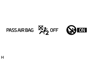
The occupant classification system detects the front passenger seat condition. It then displays the instrument panel passenger airbag assembly and lower No. 2 instrument panel airbag assembly condition (activated/not activated) using the passenger airbag ON/OFF indicator.
HINT:
Approximately 6 seconds after the power switch is turned on (IG), the passenger airbag ON/OFF indicator will indicate ON/OFF depending on the following conditions.
|
Front Passenger Seat Condition |
Passenger Airbag ON/OFF Indicator |
SRS Warning Light | |
|---|---|---|---|
|
ON Indicator | OFF Indicator | ||
|
Vacant | OFF |
ON | OFF |
|
Adult*1 is seated | ON |
OFF | OFF |
|
Child*2 is seated | ON or OFF*2 |
OFF or ON*2 | OFF |
|
Child restraint system is installed |
OFF | ON |
OFF |
| Occupant classification system failure |
OFF | ON |
ON |
CAUTION / NOTICE / HINT
NOTICE:
Click here 
PROCEDURE
|
1. | CHECK SRS WARNING LIGHT |
(a) Turn the power switch on (IG), and check the SRS warning light condition.
OK:
After the primary check period, the SRS warning light turns off.
HINT:
The primary check is performed for approximately 6 seconds after the power switch is turned on (IG).
| NG |  | GO TO AIRBAG SYSTEM |
|
| 2. |
PERFORM ZERO POINT CALIBRATION |
(a) Using the Techstream, perform Zero Point Calibration.
Click here
OK:
"Zero Point Calibration is complete." is displayed.
| OK | | END |
|
| 3. |
RETIGHTEN FRONT SEAT ASSEMBLY RH BOLT |
(a) Loosen the 4 installation bolts of the front seat assembly RH.
(b) Tighten the 4 installation bolts of the front seat assembly RH to the specified torque.
Click here
|
| 4. |
PERFORM ZERO POINT CALIBRATION |
(a) Using the Techstream, perform Zero Point Calibration.
Click here
OK:
"Zero Point Calibration is complete." is displayed.
| OK | | END |
|
| 5. |
READ VALUE USING TECHSTREAM |
(a) Turn the power switch off.
(b) Connect the Techstream to the DLC3.
(c) Turn the power switch on (IG).
(d) Turn the Techstream on.
(e) Enter the following menus: Body Electrical / Occupant Detection / Data List.
(f) Read the Data List according to the display on the Techstream.
Body Electrical > Occupant Detection > Data List|
Tester Display | Measurement Item |
Range | Normal Condition |
Diagnostic Note |
|---|---|---|---|---|
|
Passenger Buckle SW | Front passenger side buckle switch |
NG, Set or Unset | Set: Front passenger seat belt is fastened Unset: Front passenger seat belt is not fastened |
"NG" will be displayed immediately after the power switch is turned on (IG). |
|
Tester Display |
|---|
| Passenger Buckle SW |
OK:
The Techstream display changes correctly in accordance with the operation of the front passenger side buckle switch.
| NG | | GO TO STEP 9 |
|
| 6. |
CHECK CONNECTORS |
(a) Turn the power switch off.
(b) Disconnect the cable from the negative (-) auxiliary battery terminal.
(c) Disconnect the connectors from the occupant detection ECU, front occupant classification sensor LH and rear occupant classification sensor LH.
(d) Check that the terminals of the connectors are not deformed or damaged.
OK:
The terminals are not deformed or damaged.
| NG | | REPLACE FRONT SEAT WIRE RH |
|
| 7. |
REPLACE OCCUPANT DETECTION ECU |
(a) Connect the connectors to the front occupant classification sensor LH and rear occupant classification sensor LH.
(b) Replace the occupant detection ECU.
Click here
(c) Connect the cable to the negative (-) auxiliary battery terminal.
|
| 8. |
PERFORM ZERO POINT CALIBRATION |
(a) Using the Techstream, perform Zero Point Calibration.
Click here
| NEXT | | END |
| 9. |
CHECK CONNECTORS |
(a) Turn the power switch off.
(b) Disconnect the cable from the negative (-) auxiliary battery terminal.
(c) Disconnect the connectors from the occupant detection ECU and front seat inner belt assembly RH.
(d) Check that the terminals of the connectors are not deformed or damaged.
OK:
The terminals are not deformed or damaged.
| NG | | REPLACE FRONT SEAT WIRE RH |
|
| 10. |
REPLACE FRONT SEAT INNER BELT ASSEMBLY RH |
(a) Turn the power switch off.
(b) Disconnect the cable from the negative (-) auxiliary battery terminal.
(c) Replace the front seat inner belt assembly RH.
Click here
(d) Connect the cable to the negative (-) auxiliary battery terminal.
|
| 11. |
PERFORM ZERO POINT CALIBRATION |
(a) Using the Techstream, perform Zero Point Calibration.
Click here
| NEXT | | END |
DESCRIPTION
The occupant detection ECU sends/receives signals to/from each ECU via CAN communication.
|
DTC No. | Detection Item |
DTC Detection Condition | Trouble Area |
|---|---|---|---|
|
U0125 | Lost Communication with Multi-axis Acceleration Sensor Module |
CAN communication error between occupant detection ECU and acceleration sensor (CAN communication system malfunction) |
CAN communication system |
|
U0129 | Lost Communication with Brake System Control Module |
CAN communication error between occupant detection ECU and skid control ECU (CAN communication system malfunction) |
CAN communication system |
CAUTION / NOTICE / HINT
Refer to troubleshooting in CAN Communication System.
Click here

PROCEDURE
| 1. |
GO TO CAN COMMUNICATION SYSTEM |
(a) Go to CAN communication system.
Click here
| NEXT |  | END |
Toyota Avalon (XX50) 2019-2022 Service & Repair Manual > Electronically Controlled Brake System(for Hv Model): Brake Hold Standby Indicator Light Circuit. Brake Warning Light does not Come ON. Brake Warning Light Remains ON
Brake Hold Standby Indicator Light Circuit DESCRIPTION The brake hold standby indicator light turns on if brake hold control is possible when the following conditions required for operation standby are met and the brake hold switch (electric parking brake switch assembly) is turned on while the powe ...