REMOVAL CAUTION / NOTICE / HINT The necessary procedures (adjustment, calibration, initialization or registration) that must be performed after parts are removed and installed, or replaced during side No. 2 airbag sensor removal/installation are shown below. Necessary Procedures After Parts Removed/Installed/Replaced (for Gasoline Model)
HINT:
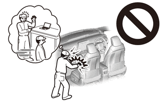
PROCEDURE 1. PRECAUTION CAUTION: Be sure to read Precaution thoroughly before servicing. for Gasoline Model: Click here
for HV Model: Click here
 NOTICE: After turning the engine switch (for Gasoline Model) or power switch (for HV Model) off, waiting time may be required before disconnecting the cable from the negative (-) auxiliary battery terminal. Therefore, make sure to read the disconnecting the cable from the negative (-) auxiliary battery terminal notices before proceeding with work. Click here
2. REMOVE LUGGAGE TRIM SERVICE HOLE COVER (for HV Model) Click here 3. DISCONNECT CABLE FROM NEGATIVE AUXILIARY BATTERY TERMINAL for Gasoline Model: Click here for HV Model: Click here
CAUTION: Wait at least 90 seconds after disconnecting the cable from the negative (-) auxiliary battery terminal to disable the SRS system. 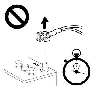 NOTICE: When disconnecting the cable, some systems need to be initialized after the cable is reconnected. Click here 4. DISCONNECT REAR CENTER SEAT OUTER BELT ASSEMBLY Click here 5. REMOVE REAR SEAT CUSHION ASSEMBLY Click here 6. REMOVE REAR SEAT CUSHION LOCK HOOK Click here 7. DISCONNECT REAR DOOR OPENING TRIM WEATHERSTRIP HINT: Disconnect the rear door opening trim weatherstrip to the extent that allows the removal of the rear side seatback assembly. 8. REMOVE REAR SIDE SEATBACK ASSEMBLY Click here
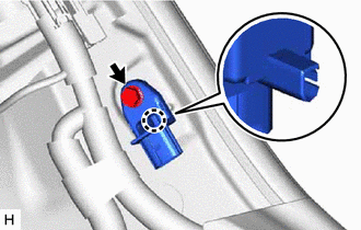
9. REMOVE SIDE NO. 2 AIRBAG SENSOR (a) Check that the engine switch (for Gasoline Model) or power switch (for HV Model) is off. (b) Check that the cable is disconnected from the negative (-) auxiliary battery terminal. CAUTION: Wait at least 90 seconds after disconnecting the cable from the negative (-) auxiliary battery terminal to disable the SRS system. (c) Disconnect the connector from the side No. 2 airbag sensor. NOTICE: When disconnecting any airbag connector, take care not to damage the airbag wire harness. (1) Push down the white housing lock and slide the yellow CPA. (At this time, the connector cannot be disconnected yet.) 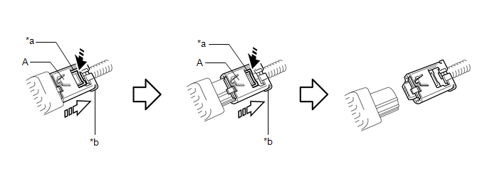
(2) Push down the white housing lock again and disconnect the connector. NOTICE: Do not push down the part (A) shown in the illustration when disconnecting the connector.
(e) Check that the position of the white housing lock is as shown in the illustration. 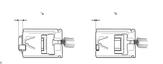
| |||||||||||||||||||||||||||||||||||||||||||||||||||||||
Toyota Avalon (XX50) 2019-2022 Service & Repair Manual > Tire Pressure Warning System(for Hv Model): Lost Communication with Brake System Control Module (U0129)
DESCRIPTION The tire pressure warning ECU and receiver receives signals from the skid control ECU (brake booster with master cylinder assembly) via CAN communication system. DTC No. Detection Item DTC Detection Condition Trouble Area Note U0129 Lost Communication with Brake System Control Module Los ...