REMOVAL CAUTION / NOTICE / HINT The necessary procedures (adjustment, calibration, initialization or registration) that must be performed after parts are removed and installed, or replaced during horn button assembly removal/installation are shown below. Necessary Procedures After Parts Removed/Installed/Replaced (for Gasoline Model)
PROCEDURE 1. PRECAUTION CAUTION: Be sure to read Precaution thoroughly before servicing. for Gasoline Model: Click here for HV Model: Click here
 NOTICE: After turning the engine switch (for Gasoline Model) or power switch (for HV Model) off, waiting time may be required before disconnecting the cable from the negative (-) auxiliary battery terminal. Therefore, make sure to read the disconnecting the cable from the negative (-) auxiliary battery terminal notices before proceeding with work. Click here
2. REMOVE LUGGAGE TRIM SERVICE HOLE COVER (for HV Model) Click here 3. DISCONNECT CABLE FROM NEGATIVE AUXILIARY BATTERY TERMINAL for Gasoline Model: Click here for HV Model: Click here
CAUTION: Wait at least 90 seconds after disconnecting the cable from the negative (-) auxiliary battery terminal to disable the SRS system. 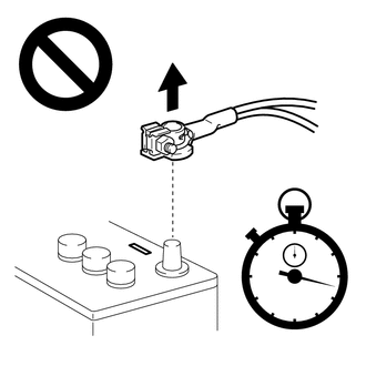 NOTICE: When disconnecting the cable, some systems need to be initialized after the cable is reconnected. Click here 4. REMOVE LOWER NO. 2 STEERING WHEEL COVER (a) Using a screwdriver with its tip wrapped with protective tape, disengage each claw to remove the 3 lower No. 2 steering wheel covers. HINT: Be careful when disengaging the claws, as the lower No. 2 steering wheel cover may fly off. 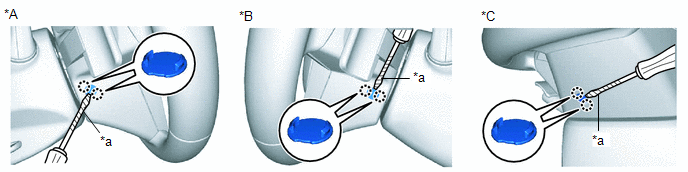
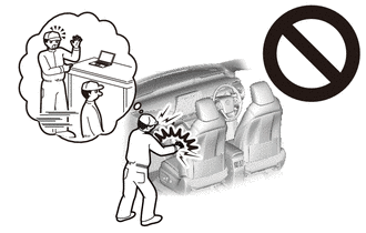
5. REMOVE HORN BUTTON ASSEMBLY CAUTION: When storing the horn button assembly, keep the airbag deployment side facing upward. 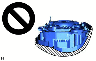
(a) Check that the engine switch (for Gasoline Model) or power switch (for HV Model) is off. (b) Check that the cable is disconnected from the negative (-) auxiliary battery terminal. CAUTION: Wait at least 90 seconds after disconnecting the cable from the negative (-) auxiliary battery terminal to disable the SRS system. (c) Using a screwdriver, push in the 3 torsion springs to disengage the 3 pins as shown in the illustration. 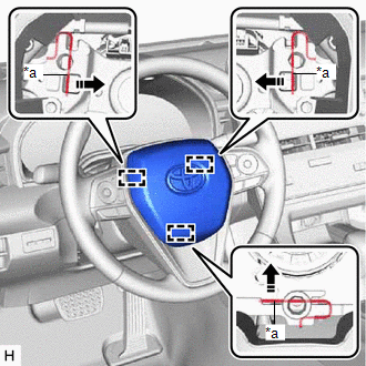
NOTICE: Lightly hold the horn button assembly so that it does not fall. HINT: Insert the screwdriver from the installation holes for the 3 lower No. 2 steering wheel covers. (d) Pull out the horn button assembly from the steering wheel assembly and hold the horn button assembly with one hand. NOTICE: When separating the horn button assembly, do not pull the airbag wire harness. (e) Disconnect the horn connector from the horn button assembly. 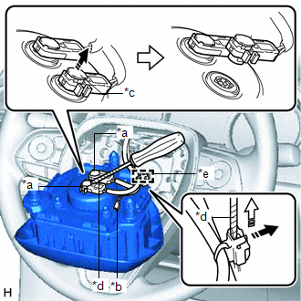
(f) Using a screwdriver with its tip wrapped with protective tape, release the 2 airbag connector locking buttons. (g) Disconnect the 2 airbag connectors. NOTICE: When disconnecting any airbag connector, take care not to damage the airbag wire harness. (h) Using a screwdriver with its tip wrapped with protective tape, release the lock and remove the wire harness clamp to remove the horn button assembly. | ||||||||||||||||||||||||||||||||||||||||||||||||||||||||||||||||||||||||
Toyota Avalon (XX50) 2019-2022 Service & Repair Manual > Smart Key System(for Start Function, Hv Model): Customize Parameters
CUSTOMIZE PARAMETERS CUSTOMIZE SMART KEY SYSTEM (for Start Function, HV Model) NOTICE: When the customer requests a change in a function, first make sure that the function can be customized. Record the current settings before customizing. HINT: The following items can be customized. (a) Customizing ...


