DESCRIPTION
If the entry lock and wireless door lock operations cannot be performed, the electrical key and tire pressure monitoring system receiver assembly may be malfunctioning, or there may be wave interference or problems in the communication which is used for the entry and wireless function between the electrical key and tire pressure monitoring system receiver assembly and certification ECU (smart key ECU assembly).
WIRING DIAGRAM

CAUTION / NOTICE / HINT
NOTICE:
Click here 
Click here
Click here
Click here
) after registration (Click here
) of the transmitter IDs into the electrical key and tire pressure
monitoring system receiver assembly if the electrical key and tire
pressure monitoring system receiver assembly has been replaced.
PROCEDURE
|
1. | INSPECT BATTERY VOLTAGE |
(a) Measure the battery voltage.
Standard Voltage:
11 to 14 V
HINT:
It may be possible to tell whether the battery is discharged by operating the horn.
If the voltage is below 11 V, recharge or replace the battery before proceeding to the next step.
|
| 2. |
CHECK FOR DTC |
(a) Open the driver door using the mechanical key built into the electrical key transmitter sub-assembly.
(b) Check for DTCs.
Body Electrical > Smart Key > Trouble Codes|
Result | Proceed to |
|---|---|
|
DTCs are not output | A |
|
DTCs are output | B |
| B |
 | GO TO DIAGNOSTIC TROUBLE CODE CHART |
|
| 3. |
CHECK DOOR AJAR WARNING |
(a) When the doors are locked by operating the entry lock function with all doors closed, check that the door ajar warning operates.
HINT:
Be sure to check the following before performing the procedure.
|
Result | Proceed to |
|---|---|
|
The wireless buzzer does not sound |
A |
| The wireless buzzer sounds |
B |
| B |
| GO TO LIGHTING SYSTEM (Proceed to Door Courtesy Switch Circuit) |
|
| 4. |
CHECK POWER DOOR LOCK CONTROL SYSTEM |
(a) When the door control switch on the multiplex network master switch assembly is operated, check that the doors unlock and lock according to the switch operation.
Click here
|
Result | Proceed to |
|---|---|
|
Power door lock function operates normally |
A |
| Power door lock function does not operate normally |
B |
| B |
| GO TO POWER DOOR LOCK CONTROL SYSTEM |
|
| 5. |
CHECK KEY DIAGNOSTIC MODE |
(a) Check the following antennas in key diagnostic mode.
Body Electrical > Smart Key > Utility|
Tester Display |
|---|
| Communication Check(Key Diag Mode) |
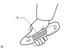
| (1) Check the electrical key antenna (for driver door): When the electrical key transmitter sub-assembly is brought within 0.7 to 1 m (2.30 to 3.28 ft.) of the front door outside handle assembly (for driver door), check that the wireless buzzer sounds. HINT:
|
|
| (2) Check the electrical key antenna (for front passenger door): When the electrical key transmitter sub-assembly is brought within 0.7 to 1 m (2.30 to 3.28 ft.) of the front door outside handle assembly (for front passenger door), check that the wireless buzzer sounds. HINT:
|
|
| (3) Check the No. 1 indoor electrical key antenna assembly (front floor): When the electrical key transmitter sub-assembly is at either inspection point, check that the wireless buzzer sounds. HINT:
|
|
| (4) Check the No. 1 indoor electrical key antenna assembly (rear floor): When the electrical key transmitter sub-assembly is at either inspection point, check that the wireless buzzer sounds. HINT:
|
|
| (5) Check the No. 1 indoor electrical key antenna assembly (inside luggage compartment): When the electrical key transmitter sub-assembly is at either inspection point, check that the wireless buzzer sounds. HINT:
|
|
| (6) Check the electrical key antenna (outside luggage compartment): When the electrical key transmitter sub-assembly is brought within 0.7 to 1 m (2.30 to 3.28 ft.) of the electrical key antenna (outside luggage compartment), check that the wireless buzzer sounds. HINT:
OK: Wireless buzzer sounds. |
|
|
Result | Proceed to |
|---|---|
|
Key diagnostic mode inspections fail for both channels |
A |
| Key diagnostic mode inspections succeed for both channels |
B |
| Key diagnostic mode inspection succeeds for only one of the channels |
C |
| B |
| GO TO STEP 18 |
| C |
| GO TO STEP 28 |
|
| 6. |
CHECK WAVE ENVIRONMENT |
(a) Bring the electrical key transmitter sub-assembly near the electrical key and tire pressure monitoring system receiver assembly and perform a wireless operation 2 or more times*.
HINT:
|
Result | Proceed to |
|---|---|
|
Wireless function does not operate normally |
A |
| Wireless function operates normally |
B |
| B |
| AFFECTED BY WAVE INTERFERENCE |
|
| 7. |
CHECK TRANSMITTER BATTERY |
(a) Check the transmitter battery level of the electrical key transmitter sub-assembly that was checked first.
(1) Press and hold the lock switch of the electrical key transmitter sub-assembly for 5 seconds and check the number of times that the LED illuminates.
HINT:
Click here
|
Result | Proceed to |
|---|---|
|
LED illuminates 3 times or more when switch is pressed and held |
A |
| LED does not illuminate when switch is pressed and held |
B |
| LED illuminates once or twice but not a third time |
C |
| B |
| GO TO STEP 17 |
| C |
| REPLACE TRANSMITTER BATTERY |
|
| 8. |
CHECK ELECTRICAL KEY TRANSMITTER SUB-ASSEMBLY |
(a) Check if there is another electrical key transmitter sub-assembly available that is already registered to the vehicle.
|
Result | Proceed to |
|---|---|
|
Another registered electrical key transmitter sub-assembly is not available |
A |
| Another registered electrical key transmitter sub-assembly is available |
B |
| B |
| GO TO STEP 10 |
|
| 9. |
ELECTRICAL KEY TRANSMITTER SUB-ASSEMBLY REGISTRATION (NEW ELECTRICAL KEY TRANSMITTER SUB-ASSEMBLY) |
(a) Register a new electrical key transmitter sub-assembly.
Click here
|
| 10. |
CHECK ENTRY LOCK OPERATION |
(a) Using another registered electrical key transmitter sub-assembly, check that the function operates normally.
|
Result | Proceed to |
|---|---|
|
Entry function does not operate normally |
A |
| Entry function operates normally |
B |
| B |
| END (ELECTRICAL KEY TRANSMITTER SUB-ASSEMBLY WAS DEFECTIVE) |
|
| 11. |
CHECK HARNESS AND CONNECTOR (CERTIFICATION ECU (SMART KEY ECU ASSEMBLY) - ELECTRICAL KEY AND TIRE PRESSURE MONITORING SYSTEM RECEIVER AND BODY GROUND) |
(a) Disconnect the K10 certification ECU (smart key ECU assembly) connector.
(b) Disconnect the K11 electrical key and tire pressure monitoring system receiver assembly connector.
(c) Measure the resistance according to the value(s) in the table below.
Standard Resistance:
|
Tester Connection | Condition |
Specified Condition |
|---|---|---|
|
K10-18 (RCO) - K11-8 (+5) |
Always | Below 1 Ω |
|
K10-19 (RDAM) - K11-2 (DATA) |
Always | Below 1 Ω |
|
K10-20 (CSEL) - K11-6 (CSEL) |
Always | Below 1 Ω |
|
K11-12 (GND) - Body ground |
Always | Below 1 Ω |
|
K10-18 (RCO) or K11-8 (+5) - Other terminals and body ground |
Always | 10 kΩ or higher |
|
K10-19 (RDAM) or K11-2 (DATA) - Other terminals and body ground |
Always | 10 kΩ or higher |
|
K10-20 (CSEL) or K11-6 (CSEL) - Other terminals and body ground |
Always | 10 kΩ or higher |
| NG | | REPAIR OR REPLACE HARNESS OR CONNECTOR |
|
| 12. |
CHECK ENTRY LOCK OPERATION |
(a) Connect all connectors and check that the function operates normally.
Click here
|
Result | Proceed to |
|---|---|
|
Entry function does not operate normally |
A |
| Entry function operates normally |
B |
| B |
| END (CONNECTOR WAS NOT CONNECTED SECURELY) |
|
| 13. |
CHECK ELECTRICAL KEY AND TIRE PRESSURE MONITORING SYSTEM RECEIVER ASSEMBLY |
(a) Measure the resistance according to the value(s) in the table below.
Standard Resistance:
|
Tester Connection | Condition |
Specified Condition |
|---|---|---|
|
K11-12 (GND) - Body ground |
Always | Below 1 Ω |
| (b) Using an oscilloscope, check the waveform. OK:
|
|
| NG | | REPLACE ELECTRICAL KEY AND TIRE PRESSURE MONITORING SYSTEM RECEIVER ASSEMBLY |
|
| 14. |
CHECK CERTIFICATION ECU (SMART KEY ECU ASSEMBLY) |
| (a) Measure the voltage according to the value(s) in the table below. Standard Voltage:
|
|
| (b) Using an oscilloscope, check the waveform. OK:
|
|
| NG | | REPLACE CERTIFICATION ECU (SMART KEY ECU ASSEMBLY) |
|
| 15. |
REPLACE CERTIFICATION ECU (SMART KEY ECU ASSEMBLY) |
(a) Replace the certification ECU (smart key ECU assembly) and perform registration again.
HINT:
Click here
Click here
|
| 16. |
CHECK WIRELESS DOOR LOCK CONTROL SYSTEM |
(a) Check that the wireless function operates normally.
Click here
|
Result | Proceed to |
|---|---|
|
Wireless door lock function operates normally |
A |
| Wireless door lock function does not operate normally |
B |
| A |
| END (CERTIFICATION ECU (SMART KEY ECU ASSEMBLY) WAS DEFECTIVE) |
| B |
| REPLACE MAIN BODY ECU (MULTIPLEX NETWORK BODY ECU) |
| 17. |
INSPECT TRANSMITTER BATTERY |
(a) Inspect the transmitter battery.
Click here
NOTICE:
Do not wrap the lead wire around a terminal, wedge it between terminals, or solder it. The terminal may be deformed or damaged, and the transmitter battery will not be able to be installed correctly.
| OK | | REPLACE ELECTRICAL KEY TRANSMITTER SUB-ASSEMBLY |
| NG | | REPLACE TRANSMITTER BATTERY |
| 18. |
PERFORM REGISTRATION |
(a) Perform registration of the B code.
Click here
|
| 19. |
CHECK ENTRY LOCK OPERATION |
(a) After completing B code registration, check that the entry lock and unlock functions can be operated 2 times consecutively.
Click here
|
Result | Proceed to |
|---|---|
|
Entry function does not operate normally |
A |
| Entry function operates normally |
B |
| B |
| END (B CODE REGISTRATION FAILED) |
|
| 20. |
READ VALUE USING TECHSTREAM (B CODE) |
(a) Connect the Techstream to the DLC3.
(b) Turn the engine switch on (IG).
(c) Turn the Techstream on.
(d) Enter the following menus: Body Electrical / Smart Key / Data List.
(e) Read the Data List according to the display on the Techstream.
Body Electrical > Smart Key > Data List|
Tester Display | Measurement Item |
Range | Normal Condition |
Diagnostic Note |
|---|---|---|---|---|
|
B Code | B code registration status |
No Regd or Regd | No Regd: B code not registered correctly Regd: B code registered correctly |
- |
|
Tester Display |
|---|
| B Code |
|
Result | Proceed to |
|---|---|
|
"No Regd" is displayed on the Techstream |
A |
| "Regd" is displayed on the Techstream |
B |
| B |
| REPLACE MAIN BODY ECU (MULTIPLEX NETWORK BODY ECU) |
|
| 21. |
READ VALUE USING TECHSTREAM (B CODE DIFFERENCE) |
(a) Connect the Techstream to the DLC3.
(b) Turn the engine switch on (IG).
(c) Turn the Techstream on.
(d) Enter the following menus: Body Electrical / Smart Key / Data List.
(e) Read the Data List according to the display on the Techstream.
Body Electrical > Smart Key > Data List|
Tester Display | Measurement Item |
Range | Normal Condition |
Diagnostic Note |
|---|---|---|---|---|
|
B Code Difference | B code mismatch |
No or Yes | No: Communication normal Yes: Communication malfunction |
- |
|
Tester Display |
|---|
| B Code Difference |
|
Result | Proceed to |
|---|---|
|
"No" is displayed on the Techstream |
A |
| "Yes" is displayed on the Techstream |
B |
| B |
| REPLACE CERTIFICATION ECU (SMART KEY ECU ASSEMBLY) |
|
| 22. |
CHECK CERTIFICATION ECU (SMART KEY ECU ASSEMBLY) |
(a) Measure the voltage while checking the Data List on the Techstream.
(1) Connect the Techstream to the DLC3.
(2) Turn the engine switch on (IG).
(3) Turn the Techstream on.
(4) Enter the following menus: Body Electrical / Power Source Control / Data List.
(5) Read the Data List according to the display on the Techstream.

|
*a | Component with harness connected (Certification ECU (Smart Key ECU Assembly)) |
- | - |
|
Tester Display | Measurement Item |
Range | Normal Condition |
Diagnostic Note |
|---|---|---|---|---|
|
Power Supply Condition |
Power supply state | All OFF, ACC ON, IG ON or ST ON |
All OFF: Engine switch off ACC ON: Engine switch on (ACC) IG ON: Engine switch on (IG) ST ON: Sending engine start request signal |
- |
|
Tester Display |
|---|
| Power Supply Condition |
Standard Voltage:
|
Tester Connection | Condition |
Specified Condition |
|---|---|---|
|
G40-17 (IG1D) - Body ground |
Engine switch off | Below 1 V |
|
Engine switch on (ACC) |
Below 1 V | |
|
Engine switch on (IG) |
9 V or higher | |
|
G40-16 (ACCD) - Body ground |
Engine switch off | Below 1 V |
|
Engine switch on (ACC) |
9 V or higher | |
|
Engine switch on (IG) |
9 V or higher |
| NG | | REPLACE CERTIFICATION ECU (SMART KEY ECU ASSEMBLY) |
|
| 23. |
READ VALUE USING TECHSTREAM (ACC SW, IG SW) |
(a) Connect the Techstream to the DLC3.
(b) Turn the engine switch on (IG).
(c) Turn the Techstream on.
(d) Enter the following menus: Body Electrical / Main Body / Data List.
(e) Read the Data List according to the display on the Techstream.
Body Electrical > Main Body > Data List|
Tester Display | Measurement Item |
Range | Normal Condition |
Diagnostic Note |
|---|---|---|---|---|
|
ACC SW | Engine switch status |
OFF or ON | OFF: Engine switch off ON: Engine switch on (ACC) |
"ON" is also displayed when the engine switch is on (IG). |
|
IG SW | Engine switch status |
OFF or ON | OFF: Engine switch off ON: Engine switch on (IG) |
"OFF" is also displayed when the engine switch is on (ACC). |
|
Tester Display |
|---|
| ACC SW |
|
IG SW |
HINT:
If the certification ECU (smart key ECU assembly) misjudges for any reason that the engine switch is on (IG) even though the engine switch is off, the entry lock and unlock functions will be disabled.
|
Result | Proceed to |
|---|---|
|
The main body ECU (multiplex network body ECU) judges properly that the power source is off when the engine switch is off |
A |
| The main body ECU (multiplex network body ECU) does not judge properly that the power source is off when the engine switch is off |
B |
| B |
| TROUBLESHOOT MAIN BODY ECU (MULTIPLEX NETWORK BODY ECU) |
|
| 24. |
CHECK HARNESS AND CONNECTOR (BODY GROUND, POWER SUPPLY) |
| (a) Disconnect the G40 certification ECU (smart key ECU assembly) connector. |
|
(b) Measure the resistance according to the value(s) in the table below.
Standard Resistance:
|
Tester Connection | Condition |
Specified Condition |
|---|---|---|
|
G40-18 (E) - Body ground |
Always | Below 1 Ω |
(c) Measure the voltage according to the value(s) in the table below.
Standard Voltage:
|
Tester Connection | Condition |
Specified Condition |
|---|---|---|
|
G40-15 (CUTB) - Body ground |
Always | 11 to 14 V |
| NG | | REPAIR OR REPLACE HARNESS OR CONNECTOR |
|
| 25. |
CHECK ENTRY LOCK OPERATION |
(a) Disconnect and reconnect the certification ECU (smart key ECU assembly) connectors.
(b) Check that the function operates normally.
Click here
|
Result | Proceed to |
|---|---|
|
Entry function does not operate normally |
A |
| Entry function operates normally |
B |
| B |
| END (CONNECTOR WAS NOT CONNECTED SECURELY) |
|
| 26. |
REPLACE CERTIFICATION ECU (SMART KEY ECU ASSEMBLY) |
(a) Replace the certification ECU (smart key ECU assembly) with a new one and perform registration again.
HINT:
Click here
Click here
|
| 27. |
CHECK WIRELESS DOOR LOCK CONTROL SYSTEM |
(a) Check that the function operates normally.
Click here
|
Result | Proceed to |
|---|---|
|
Wireless door lock function operates normally |
A |
| Wireless door lock function does not operate normally |
B |
| A |
| END (CERTIFICATION ECU (SMART KEY ECU ASSEMBLY) WAS DEFECTIVE) |
| B |
| REPLACE MAIN BODY ECU (MULTIPLEX NETWORK BODY ECU) |
| 28. |
CHECK WAVE ENVIRONMENT |
(a) Bring the electrical key transmitter sub-assembly near the electrical key and tire pressure monitoring system receiver assembly and perform a wireless operation 2 or more times*.
HINT:
|
Result | Proceed to |
|---|---|
|
Wireless function does not operate normally |
A |
| Wireless function operates normally 1 or more times. |
B |
| B |
| AFFECTED BY WAVE INTERFERENCE |
|
| 29. |
CHECK ELECTRICAL KEY TRANSMITTER SUB-ASSEMBLY |
(a) Check if there is another electrical key transmitter sub-assembly available that is already registered to the vehicle.
|
Result | Proceed to |
|---|---|
|
Another registered electrical key transmitter sub-assembly is not available |
A |
| Another registered electrical key transmitter sub-assembly is available |
B |
| B |
| GO TO STEP 31 |
|
| 30. |
ELECTRICAL KEY TRANSMITTER SUB-ASSEMBLY REGISTRATION (NEW ELECTRICAL KEY TRANSMITTER SUB-ASSEMBLY) |
(a) Register a new electrical key transmitter sub-assembly.
Click here
|
| 31. |
CHECK WAVE ENVIRONMENT |
(a) Bring another registered electrical key transmitter sub-assembly near the electrical key and tire pressure monitoring system receiver assembly and perform a wireless operation 2 or more times*.
HINT:
|
Result | Proceed to |
|---|---|
|
Wireless function does not operate normally |
A |
| Wireless function operates normally 1 or more times. |
B |
| B |
| END (ELECTRICAL KEY TRANSMITTER SUB-ASSEMBLY WAS DEFECTIVE) |
|
| 32. |
CHECK HARNESS AND CONNECTOR (CERTIFICATION ECU (SMART KEY ECU ASSEMBLY) - ELECTRICAL KEY AND TIRE PRESSURE MONITORING SYSTEM RECEIVER ASSEMBLY) |
(a) Disconnect the K11 electrical key and tire pressure monitoring system receiver assembly connector.
(b) Disconnect the K10 certification ECU (smart key ECU assembly) connector.
(c) Measure the resistance according to the value(s) in the table below.
Standard Resistance:
|
Tester Connection | Condition |
Specified Condition |
|---|---|---|
|
K11-6 (CSEL) - K10-20 (CSEL) |
Always | Below 1 Ω |
|
K11-6 (CSEL) or K10-20 (CSEL) - Other terminals and body ground |
Always | 10 kΩ or higher |
| NG | | REPAIR OR REPLACE HARNESS OR CONNECTOR |
|
| 33. |
CHECK ENTRY LOCK OPERATION |
(a) Connect all connectors and check that the function operates normally.
Click here
|
Result | Proceed to |
|---|---|
|
Entry function does not operate normally |
A |
| Entry function operates normally |
B |
| B |
| END (CONNECTOR WAS NOT CONNECTED SECURELY) |
|
| 34. |
CHECK CERTIFICATION ECU (SMART KEY ECU ASSEMBLY) |
| (a) Measure the voltage according to the value(s) in the table below. Standard Voltage:
|
|
| NG | | REPLACE CERTIFICATION ECU (SMART KEY ECU ASSEMBLY) |
|
| 35. |
CHECK ELECTRICAL KEY AND TIRE PRESSURE MONITORING SYSTEM RECEIVER ASSEMBLY |
(a) Enter key diagnostic mode and select the channel for which the wireless buzzer did not sound.
| (b) Using an oscilloscope, check the waveform. OK:
HINT: Inspection should be performed while the electrical key antenna check in key diagnostic mode is being performed on the failed channel (the channel in which the buzzer did not sound). |
|
| NG | | REPLACE ELECTRICAL KEY AND TIRE PRESSURE MONITORING SYSTEM RECEIVER ASSEMBLY |
|
| 36. |
REPLACE CERTIFICATION ECU (SMART KEY ECU ASSEMBLY) |
(a) Replace the certification ECU (smart key ECU assembly) and perform registration again.
HINT:
Click here
Click here
|
| 37. |
CHECK WIRELESS DOOR LOCK CONTROL SYSTEM |
(a) Check that the function operates normally.
Click here
|
Result | Proceed to |
|---|---|
|
Wireless door lock function operates normally |
A |
| Wireless door lock function does not operate normally |
B |
| A |
| END (CERTIFICATION ECU (SMART KEY ECU ASSEMBLY) WAS DEFECTIVE) |
| B |
| REPLACE MAIN BODY ECU (MULTIPLEX NETWORK BODY ECU) |
DESCRIPTION
When the wireless operation can be used to lock and unlock the doors, communication between the electrical key and tire pressure monitoring system receiver assembly and certification ECU (smart key ECU assembly) is normal. If the entry lock and unlock functions do not operate, the entry cancel function may be set through the customize function, there may be communication problems between the electrical key transmitter sub-assembly and vehicle, or there may be wave interference.
CAUTION / NOTICE / HINT
NOTICE:
Click here
Click here
Click here
PROCEDURE
|
1. | CHECK POWER DOOR LOCK CONTROL SYSTEM |
(a) When the door control switch on the multiplex network master switch assembly is operated, check that the doors unlock and lock according to the switch operation.
Click here
OK:
Door locks operate normally.
| NG | |
GO TO POWER DOOR LOCK CONTROL SYSTEM (for Gasoline Model) |
|
| 2. |
CHECK WAVE ENVIRONMENT |
(a) Move the electrical key transmitter sub-assembly as described below and perform the operation inspection.
HINT:
| (1) Bring the electrical key transmitter sub-assembly approximately 0.3 m (0.984 ft.) from the front door outside handle assembly (for driver door) and perform a driver door entry lock and unlock operation check. HINT: Communication may not be possible if the electrical key transmitter sub-assembly is within 0.2 m (0.656 ft.) of the door handle. |
|
| (2) Bring the electrical key transmitter sub-assembly approximately 0.3 m (0.984 ft.) from the front door outside handle assembly (for front passenger door) and perform a front passenger door entry lock and unlock operation check. HINT: Communication may not be possible if the electrical key transmitter sub-assembly is within 0.2 m (0.656 ft.) of the door handle. |
|
| (3) Bring the electrical key transmitter sub-assembly approximately 0.3 m (0.984 ft.) from the electrical key antenna (outside luggage compartment) and perform an entry luggage compartment door open function check. HINT: Communication may not be possible if the electrical key transmitter sub-assembly is within 0.2 m (0.656 ft.) of the rear bumper. |
|
|
Result | Proceed to |
|---|---|
|
All operation checks fail |
A |
| All operation checks are normal |
B |
| Some operation checks are normal |
C |
| B |
| AFFECTED BY WAVE INTERFERENCE |
| C |
| GO TO OTHER PROBLEM |
|
| 3. |
CHECK KEY DIAGNOSTIC MODE |
(a) Check the following antennas in key diagnostic mode.
Body Electrical > Smart Key > Utility|
Tester Display |
|---|
| Communication Check(Key Diag Mode) |
(b) Select either channel 1 or channel 2 and perform key diagnostic mode inspection for each channel.
| (1) Check the electrical key antenna (for driver door): When the electrical key transmitter sub-assembly is brought within 0.7 to 1 m (2.30 to 3.28 ft.) of the front door outside handle assembly (for driver door), check that the wireless buzzer sounds. HINT:
|
|
| (2) Check the electrical key antenna (for front passenger door): When the electrical key transmitter sub-assembly is brought within 0.7 to 1 m (2.30 to 3.28 ft.) of the front door outside handle assembly (for front passenger door), check that the wireless buzzer sounds. HINT:
|
|
| (3) Check the electrical key antenna (outside luggage compartment): When the electrical key transmitter sub-assembly is brought within 0.7 to 1 m (2.30 to 3.28 ft.) of the electrical key antenna (outside luggage compartment), check that the wireless buzzer sounds. HINT:
OK: Wireless buzzer sounds. |
|
|
Result | Proceed to |
|---|---|
|
All diagnostic mode inspections fail |
A |
| Some diagnostic mode inspections fail (door) |
B |
| Some diagnostic mode inspections fail (outside luggage compartment) |
C |
| All diagnostic mode inspections are normal |
D |
| B |
| GO TO OTHER PROBLEM |
| C |
| GO TO OTHER PROBLEM |
| D |
| REPLACE CERTIFICATION ECU (SMART KEY ECU ASSEMBLY) |
|
| 4. |
CHECK ELECTRICAL KEY TRANSMITTER SUB-ASSEMBLY |
(a) Check if there is another electrical key transmitter sub-assembly available that is already registered to the vehicle.
|
Result | Proceed to |
|---|---|
|
Another registered electrical key transmitter sub-assembly is not available |
A |
| Another registered electrical key transmitter sub-assembly is available |
B |
| B |
| GO TO STEP 6 |
|
| 5. |
ELECTRICAL KEY TRANSMITTER SUB-ASSEMBLY REGISTRATION (NEW ELECTRICAL KEY TRANSMITTER SUB-ASSEMBLY) |
(a) Register a new electrical key transmitter sub-assembly.
Click here
|
| 6. |
CHECK ENTRY LOCK OPERATION |
(a) Using another registered electrical key transmitter sub-assembly, check that the entry function operates normally.
Click here
|
Result | Proceed to |
|---|---|
|
Entry function operates normally |
A |
| Entry function does not operate normally |
B |
| A |
| END (ELECTRICAL KEY TRANSMITTER SUB-ASSEMBLY WAS DEFECTIVE) |
| B |
| REPLACE CERTIFICATION ECU (SMART KEY ECU ASSEMBLY) |
DESCRIPTION
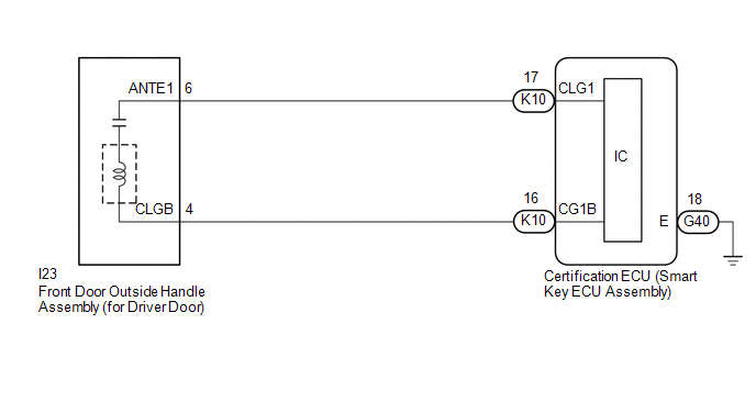
The certification ECU (smart key ECU assembly) generates a request signal and transmits the signal to the front door outside handle assembly (for driver door) (electrical key antenna) at intervals of 0.25 seconds. For the front door outside handle assembly (for driver door) (electrical key antenna) to detect when the electrical key transmitter sub-assembly is brought close to the vehicle, a signal requesting a response from the electrical key transmitter sub-assembly is transmitted within approximately 1 m (3.28 ft.) of the driver door at intervals of 0.25 seconds. DTC B27A1 is stored by the certification ECU (smart key ECU assembly) when an open is detected between the certification ECU (smart key ECU assembly) and front door outside handle assembly (for driver door) (electrical key antenna) (between terminals CLG1 and ANTE1, or terminals CG1B and CLGB).
|
DTC No. | Detection Item |
DTC Detection Condition | Trouble Area |
Note |
|---|---|---|---|---|
| B27A1 |
Open in Driver Side Electrical Antenna Circuit |
An open is detected in the circuit between the certification ECU (smart key ECU assembly) and front door outside handle assembly (for driver door) (CLG1 - ANTE1, CG1B - CLGB) (This is detected by the malfunction detection circuit in the certification ECU (smart key ECU assembly)) (1 trip detection logic*). |
|
|
|
Vehicle Condition when Malfunction Detected |
Fail-safe Operation when Malfunction Detected |
|---|---|
|
Entry lock/unlock operation cannot be performed for driver door |
- |
|
DTC No. | Data List and Active Test |
|---|---|
|
B27A1 | Key diagnostic mode can be used to perform troubleshooting |
WIRING DIAGRAM
CAUTION / NOTICE / HINT
NOTICE:
Click here 
Click here
PROCEDURE
|
1. | CHECK CONNECTOR CONNECTION |
(a) Check that the connectors are properly connected to the certification ECU (smart key ECU assembly) and front door outside handle assembly (for driver door).
OK:
Connectors are properly connected.
| NG |  | CONNECT CONNECTORS PROPERLY |
|
| 2. |
CHECK HARNESS AND CONNECTOR (CERTIFICATION ECU (SMART KEY ECU ASSEMBLY) - FRONT DOOR OUTSIDE HANDLE ASSEMBLY (FOR DRIVER DOOR)) |
(a) Disconnect the K10 certification ECU (smart key ECU assembly) connector.
(b) Disconnect the I23 front door outside handle assembly (for driver door) connector.
(c) Measure the resistance according to the value(s) in the table below.
Standard Resistance:
|
Tester Connection | Condition |
Specified Condition |
|---|---|---|
|
K10-17 (CLG1) - I23-6 (ANTE1) |
Always | Below 1 Ω |
|
K10-16 (CG1B) - I23-4 (CLGB) |
Always | Below 1 Ω |
(d) Reconnect the K10 certification ECU (smart key ECU assembly) connector.
| NG | | REPAIR OR REPLACE HARNESS OR CONNECTOR |
|
| 3. |
CHECK CERTIFICATION ECU (SMART KEY ECU ASSEMBLY) (OUTPUT TO FRONT DOOR OUTSIDE HANDLE ASSEMBLY (FOR DRIVER DOOR)) |
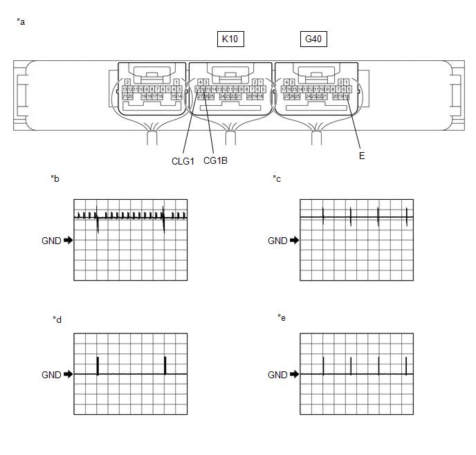
|
*a | Component with harness connected (Certification ECU (Smart Key ECU Assembly)) |
*b | Waveform 1 |
|
*c | Waveform 2 |
*d | Waveform 3 |
|
*e | Waveform 4 | - |
- |
(a) Using an oscilloscope, check the waveform.
OK:
|
Tester Connection | Condition |
Tool Setting | Specified Condition |
|---|---|---|---|
|
K10-17 (CLG1) - G40-18 (E) | Procedure:
| 5 V/DIV., 500 ms/DIV. |
Pulse generation (See waveform 1) |
|
Procedure:
| 5 V/DIV., 100 ms/DIV. |
Pulse generation (See waveform 2) | |
|
K10-16 (CG1B) - G40-18 (E) | Procedure:
| 5 V/DIV., 500 ms/DIV. |
Pulse generation (See waveform 3) |
|
Procedure:
| 5 V/DIV., 100 ms/DIV. |
Pulse generation (See waveform 4) |
Click here
| OK | | REPLACE FRONT DOOR OUTSIDE HANDLE ASSEMBLY (FOR DRIVER DOOR) |
| NG | | REPLACE CERTIFICATION ECU (SMART KEY ECU ASSEMBLY) |
DESCRIPTION
The certification ECU (smart key ECU assembly) generates a request signal and transmits the signal to the front door outside handle assembly (for front passenger door) (electrical key antenna) at intervals of 0.25 seconds. For the front door outside handle assembly (for front passenger door) (electrical key antenna) to detect when the electrical key transmitter sub-assembly is brought close to the vehicle, a signal requesting a response from the electrical key transmitter sub-assembly is transmitted within approximately 1 m (3.28 ft.) of the front passenger door at intervals of 0.25 seconds. DTC B27A2 is stored by the certification ECU (smart key ECU assembly) when an open is detected between the certification ECU (smart key ECU assembly) and front door outside handle assembly (for front passenger door) (electrical key antenna) (between terminals CLG2 and ANTE2, or terminals CG2B and CLGB).
|
DTC No. | Detection Item |
DTC Detection Condition | Trouble Area |
Note |
|---|---|---|---|---|
| B27A2 |
Open in Front Passenger Side Electrical Antenna Circuit |
An open is detected in the circuit between the certification ECU (smart key ECU assembly) and front door outside handle assembly (for front passenger door) (CLG2 - ANTE2, CG2B - CLGB) (This is detected by the malfunction detection circuit in the certification ECU (smart key ECU assembly)) (1 trip detection logic*). |
|
|
|
Vehicle Condition when Malfunction Detected |
Fail-safe Operation when Malfunction Detected |
|---|---|
|
Entry lock/unlock operation cannot be performed for front passenger door |
- |
|
DTC No. | Data List and Active Test |
|---|---|
|
B27A2 | Key diagnostic mode can be used to perform troubleshooting |
WIRING DIAGRAM

CAUTION / NOTICE / HINT
NOTICE:
Click here 
Click here
PROCEDURE
|
1. | CHECK CONNECTOR CONNECTION |
(a) Check that the connectors are properly connected to the certification ECU (smart key ECU assembly) and front door outside handle assembly (for front passenger door).
OK:
Connectors are properly connected.
| NG |  | CONNECT CONNECTORS PROPERLY |
|
| 2. |
CHECK HARNESS AND CONNECTOR (CERTIFICATION ECU (SMART KEY ECU ASSEMBLY) - FRONT DOOR OUTSIDE HANDLE ASSEMBLY (FOR FRONT PASSENGER DOOR)) |
(a) Disconnect the K10 certification ECU (smart key ECU assembly) connector.
(b) Disconnect the I7 front door outside handle assembly (for front passenger door) connector.
(c) Measure the resistance according to the value(s) in the table below.
Standard Resistance:
|
Tester Connection | Condition |
Specified Condition |
|---|---|---|
|
K10-15 (CLG2) - I7-6 (ANTE2) |
Always | Below 1 Ω |
|
K10-14 (CG2B) - I7-4 (CLGB) |
Always | Below 1 Ω |
(d) Reconnect the K10 certification ECU (smart key ECU assembly) connector.
| NG | | REPAIR OR REPLACE HARNESS OR CONNECTOR |
|
| 3. |
CHECK CERTIFICATION ECU (SMART KEY ECU ASSEMBLY) (OUTPUT TO FRONT DOOR OUTSIDE HANDLE ASSEMBLY (FOR FRONT PASSENGER DOOR)) |

|
*a | Component with harness connected (Certification ECU (Smart Key ECU Assembly)) |
*b | Waveform 1 |
|
*c | Waveform 2 |
*d | Waveform 3 |
|
*e | Waveform 4 |
- | - |
(a) Using an oscilloscope, check the waveform.
OK:
|
Tester Connection | Condition |
Tool Setting | Specified Condition |
|---|---|---|---|
|
K10-15 (CLG2) - G40-18 (E) | Procedure:
| 5 V/DIV., 500 ms/DIV. |
Pulse generation (See waveform 1) |
|
Procedure:
| 5 V/DIV., 100 ms/DIV. |
Pulse generation (See waveform 2) | |
|
K10-14 (CG2B) - G40-18 (E) | Procedure:
| 5 V/DIV., 500 ms/DIV. |
Pulse generation (See waveform 3) |
|
Procedure:
| 5 V/DIV., 100 ms/DIV. |
Pulse generation (See waveform 4) |
Click here
| OK | | REPLACE FRONT DOOR OUTSIDE HANDLE ASSEMBLY (FOR FRONT PASSENGER DOOR) |
| NG | | REPLACE CERTIFICATION ECU (SMART KEY ECU ASSEMBLY) |
DESCRIPTION
The certification ECU (smart key ECU assembly) generates a request signal and transmits the signal to the No. 1 indoor electrical key antenna assembly (inside luggage compartment). For the No. 1 indoor electrical key antenna assembly (inside luggage compartment) to detect when the electrical key transmitter sub-assembly is in the cabin, the signal from the certification ECU (smart key ECU assembly) requesting a response from the electrical key transmitter sub-assembly is transmitted inside the vehicle. DTC B27A7 is stored by the certification ECU (smart key ECU assembly) when an open is detected between the certification ECU (smart key ECU assembly) and No. 1 indoor electrical key antenna assembly (inside luggage compartment) (between terminals CLG7 and ANTE7, or terminals CG7B and CLGB).
|
DTC No. | Detection Item |
DTC Detection Condition | Trouble Area |
Note |
|---|---|---|---|---|
| B27A7 |
Open in Inside Luggage Compartment Electrical Key Oscillator Circuit |
An open is detected in the circuit between the certification ECU (smart key ECU assembly) and No. 1 indoor electrical key antenna assembly (inside luggage compartment) (CLG7 - ANTE7, CG7B - CLGB) (1 trip detection logic*). |
|
|
|
Vehicle Condition when Malfunction Detected |
Fail-safe Operation when Malfunction Detected |
|---|---|
|
When electrical key transmitter sub-assembly is in luggage compartment:
| - |
|
DTC No. | Data List and Active Test |
|---|---|
|
B27A7 | Key diagnostic mode can be used to perform troubleshooting |
WIRING DIAGRAM

CAUTION / NOTICE / HINT
NOTICE:
Click here
Click here
PROCEDURE
|
1. | CHECK CONNECTOR CONNECTION |
(a) Check that the connectors are properly connected to the certification ECU (smart key ECU assembly) and No. 1 indoor electrical key antenna assembly (inside luggage compartment).
OK:
Connectors are properly connected.
| NG | | CONNECT CONNECTORS PROPERLY |
|
| 2. |
CHECK HARNESS AND CONNECTOR (CERTIFICATION ECU (SMART KEY ECU ASSEMBLY) - NO. 1 INDOOR ELECTRICAL KEY ANTENNA ASSEMBLY (INSIDE LUGGAGE COMPARTMENT)) |
(a) Disconnect the K10 certification ECU (smart key ECU assembly) connector.
(b) Disconnect the K13 No. 1 indoor electrical key antenna assembly (inside luggage compartment) connector.
(c) Measure the resistance according to the value(s) in the table below.
Standard Resistance:
|
Tester Connection | Condition |
Specified Condition |
|---|---|---|
|
K10-11 (CLG7) - K13-1 (ANTE7) |
Always | Below 1 Ω |
|
K10-10 (CG7B) - K13-3 (CLGB) |
Always | Below 1 Ω |
(d) Reconnect the K10 certification ECU (smart key ECU assembly) connector.
| NG | | REPAIR OR REPLACE HARNESS OR CONNECTOR |
|
| 3. |
CHECK CERTIFICATION ECU (SMART KEY ECU ASSEMBLY) (OUTPUT TO NO. 1 INDOOR ELECTRICAL KEY ANTENNA ASSEMBLY (INSIDE LUGGAGE COMPARTMENT)) |

|
*a | Component with harness connected (Certification ECU (Smart Key ECU Assembly)) |
*b | Waveform 1 |
|
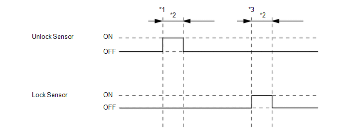
*c | Driver door lock sensor not touched |
*d | Driver door lock sensor touched |
(a) Using an oscilloscope, check the waveform.
OK:
|
Tester Connection | Condition |
Tool Setting | Specified Condition |
|---|---|---|---|
|
K10-11 (CLG7) - G40-18 (E) | Procedure:
| 2 V/DIV., 500 ms/DIV. |
Pulse generation (See waveform 1) |
|
K10-10 (CG7B) - G40-18 (E) | Procedure:
| 2 V/DIV., 500 ms/DIV. |
Pulse generation (See waveform 1) |
| OK | | REPLACE NO. 1 INDOOR ELECTRICAL KEY ANTENNA ASSEMBLY (INSIDE LUGGAGE COMPARTMENT) |
| NG | | REPLACE CERTIFICATION ECU (SMART KEY ECU ASSEMBLY) |
DESCRIPTION
The certification ECU (smart key ECU assembly) generates a request signal and transmits the signal to the electrical key antenna (outside luggage compartment). For the electrical key antenna (outside luggage compartment) to detect when the electrical key transmitter sub-assembly is brought close to the vehicle, the received request signal is transmitted within approximately 1 m (3.28 ft.) of the Luggage Compartment door. DTC B27A8 is stored by the certification ECU (smart key ECU assembly) when an open is detected between the certification ECU (smart key ECU assembly) and electrical key antenna (outside luggage compartment) (between terminals CLG8 and ANTE8, or terminals CG8B and CLGB).
|
DTC No. | Detection Item |
DTC Detection Condition | Trouble Area |
Note |
|---|---|---|---|---|
| B27A8 |
Open in Outside Luggage Compartment Electrical Key Antenna Circuit |
An open is detected in the circuit between the certification ECU (smart key ECU assembly) and electrical key antenna (outside luggage compartment) (CLG8 - ANTE8, CG8B - CLGB) (1 trip detection logic*). |
|
|
|
Vehicle Condition when Malfunction Detected |
Fail-safe Operation when Malfunction Detected |
|---|---|
|
Entry lock/unlock operation cannot be performed for luggage compartment door |
- |
|
DTC No. | Data List and Active Test |
|---|---|
|
B27A8 | Key diagnostic mode can be used to perform troubleshooting |
WIRING DIAGRAM

CAUTION / NOTICE / HINT
NOTICE:
Click here
Click here
PROCEDURE
|
1. | CHECK CONNECTOR CONNECTION |
(a) Check that the connectors are properly connected to the certification ECU (smart key ECU assembly) and electrical key antenna (outside luggage compartment).
OK:
Connectors are properly connected.
| NG | | CONNECT CONNECTORS PROPERLY |
|
| 2. |
CHECK HARNESS AND CONNECTOR (CERTIFICATION ECU (SMART KEY ECU ASSEMBLY) - ELECTRICAL KEY ANTENNA (OUTSIDE LUGGAGE COMPARTMENT)) |
(a) Disconnect the K10 certification ECU (smart key ECU assembly) connector.
(b) Disconnect the P2 electrical key antenna (outside luggage compartment) connector.
(c) Measure the resistance according to the value(s) in the table below.
Standard Resistance:
|
Tester Connection | Condition |
Specified Condition |
|---|---|---|
|
K10-13 (CLG8) - P2-2 (ANTE8) |
Always | Below 1 Ω |
|
K10-12 (CG8B) - P2-1 (CLGB) |
Always | Below 1 Ω |
(d) Reconnect the K10 certification ECU (smart key ECU assembly) connector.
| NG | | REPAIR OR REPLACE HARNESS OR CONNECTOR |
|
| 3. |
CHECK CERTIFICATION ECU (SMART KEY ECU ASSEMBLY) (OUTPUT TO ELECTRICAL KEY ANTENNA (OUTSIDE LUGGAGE COMPARTMENT)) |

|
*a | Component with harness connected (Certification ECU (Smart Key ECU Assembly)) |
*b | Waveform 1 |
(a) Using an oscilloscope, check the waveform.
OK:
|
Tester Connection | Condition |
Tool Setting | Specified Condition |
|---|---|---|---|
|
K10-13 (CLG8) - G40-18 (E) | Procedure:
| 2 V/DIV., 500 ms/DIV. |
Pulse generation (See waveform 1) |
|
K10-12 (CG8B) - G40-18 (E) | Procedure:
| 2 V/DIV., 500 ms/DIV. |
Pulse generation (See waveform 1) |
| OK | | REPLACE ELECTRICAL KEY ANTENNA (OUTSIDE LUGGAGE COMPARTMENT) |
| NG | | REPLACE CERTIFICATION ECU (SMART KEY ECU ASSEMBLY) |
CUSTOMER PROBLEM ANALYSIS CHECK
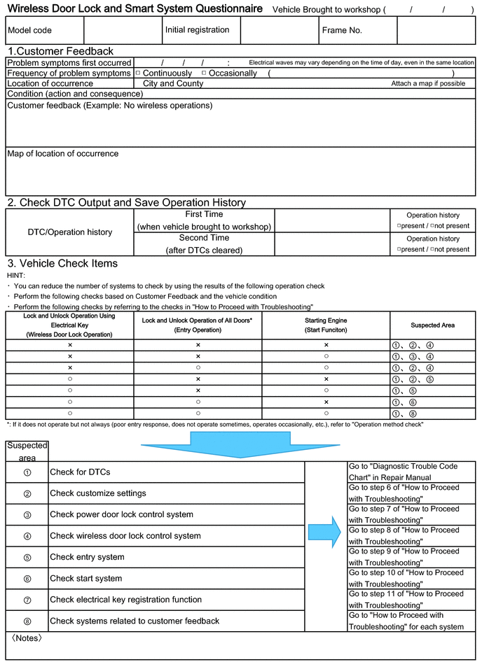
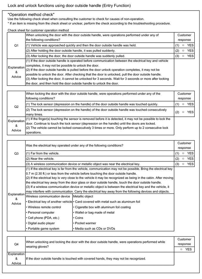
HINT:
Be sure to ask the customer in detail about the following points concerning the vehicle operating conditions, environment and problem, and then check for DTCs.
If it is suspected that wave interference is likely, be sure to ask the customer in detail about the following points concerning the vehicle operating conditions, environment and problem.
Click here 
CUSTOMIZE PARAMETERS
CUSTOMIZE SMART KEY SYSTEM (for Entry Function, Gasoline Model)
NOTICE:
HINT:
The following items can be customized.
(a) Customizing with the Techstream
(1) Connect the Techstream to the DLC3.
(2) Turn the engine switch on (IG).
(3) Turn the Techstream on.
(4) Enter the following menus: Customize Setting / Smart Key / Access or Warning.
(5) Select the setting by referring to the table below.
Smart Key / Access|
Tester Display | Description |
Default | Setting |
ECU |
|---|---|---|---|---|
| Park Wait Time |
Function that sets the period of time (lock confirmation time) that the door is prevented from being unlocked by operating the front door outside handle assembly or rear door outside handle assembly after an entry lock operation is performed. | 2.5s |
00:0.5s,01:1.5s,10:2.5s,11:5s |
Certification ECU (Smart key ECU assembly) |
|
Ignition Available Area |
Function that sets the area that the key must be in before the engine switch can be operated. |
All | 00:Front,01:All |
Certification ECU (Smart key ECU assembly) |
|
Trunk Open Mode | Function that opens the luggage compartment door when the user is carrying the electrical key transmitter sub-assembly and presses the luggage electrical key switch. | ON |
0:OFF,1:ON | Certification ECU (Smart key ECU assembly) |
|
Door Unlock Mode2 | Function that sets which doors are unlocked by the entry unlock function. |
All | 0:All,1:Driver |
Certification ECU (Smart key ECU assembly) |
|
Touch Activation Over Threshold |
Function that limits the number of times the entry lock function can be operated consecutively. When set to Not Active entry lock function can be operated an unlimited number of times consecutively. |
Active | 0:Active,1:Not Active |
Certification ECU (Smart key ECU assembly) |
|
Door Unlock Sensor Touch Time Adjust |
Function that sets the length of time the unlock sensor on the door outside handle assembly (for driver door) must be touched to unlock all of the doors | Middle |
00:OFF,01:Short,10:Middle,11:Long |
Certification ECU (Smart key ECU assembly) |
|
Tester Display | Description |
Default | Setting |
ECU |
|---|---|---|---|---|
| Key Low Battery Warning |
Enables or disables the sounding of the buzzer when the transmitter battery is low and the engine switch is turned off after being on (IG) for 20 minutes or more. | ON |
0:OFF,1:ON | Certification ECU (Smart key ECU assembly) |
(b) Customizing with the multi-display
(1) Turn the engine switch on (IG).
(2) Enter the following menus: MENU / Setup / Vehicle / Vehicle Customization / Door Lock Settings.
(3) Select the setting by referring to the table below.
|
Display | Description |
Default | Setting |
Relevant ECU |
|---|---|---|---|---|
| Select Doors to Unlock |
Function that sets which doors are unlocked by the entry unlock function. |
All Doors | All Doors or Driver's Door |
Certification ECU (Smart key ECU assembly) |
(c) Entry unlock mode change function (manual operation)
(1) The following entry unlock modes can be selected when using the entry unlock mode change function.
(2) When customizing through manual operation:
HINT:
|
Currently Selected Mode |
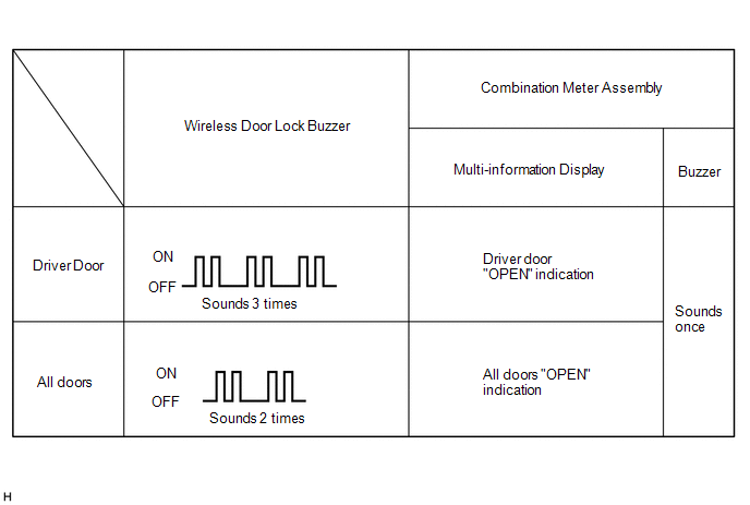
Answer-back (Wireless Buzzer) |
Answer-back (Buzzer in Combination Meter Assembly) |
|
All door unlock mode |
Buzzer sounds twice (short beeps) |
Buzzer sounds once |
|
Driver door unlock mode |
Buzzer sounds 3 times (short beeps) |
Buzzer sounds once |
HINT:
Repeat the procedure as necessary to select the desired mode.
(d) Entry cancel function (manual operation)
HINT:
While the smart key system is canceled, it is possible to lock and unlock the doors with the wireless function, and the engine can be started by holding the electrical key transmitter sub-assembly near the engine switch.
(1) The following functions are disabled when the smart key system is canceled.
(2) When canceling the smart key system through manual operation:
(3) Press the unlock switch of the electrical key transmitter sub-assembly.
(4) Open the driver door within 5 seconds of completing the step above (driver door: closed → opened).
(5) With the driver door open, press the unlock switch of the electrical key transmitter sub-assembly 2 times within 5 seconds of completing the step above.
NOTICE:
If the driver door is closed before or while pressing the unlock switch, the entry cancel setting mode will end.
(6) Perform the following procedure within 30 seconds of completing the step above.
NOTICE:
If the driver door is closed before or while pressing the unlock switch, the entry cancel setting mode will end.
(7) Close the driver door within 5 seconds (driver door: open → closed).
(8) Check that the wireless buzzer sounds twice (short beeps) to confirm that the smart key system has been canceled.
(9) Perform the following procedure to restore the smart key system to the active state from the canceled state.
HINT:
DATA LIST / ACTIVE TEST
DATA LIST
NOTICE:
HINT:
Using the Techstream to read the Data List allows the values or states of switches, sensors, actuators and other items to be read without removing any parts. This non-intrusive inspection can be very useful because intermittent conditions or signals may be discovered before parts or wiring is disturbed. Reading the Data List information early in troubleshooting is one way to save diagnostic time.
(a) Connect the Techstream to the DLC3.
(b) Turn the engine switch on (IG).
(c) Turn the Techstream on.
(d) Enter the following menus: Body Electrical / Smart Key, Main Body, Power Source Control or Combination Meter / Data List.
(e) Read the Data List according to the display on the Techstream.
Body Electrical > Smart Key > Data List|
Tester Display | Measurement Item |
Range | Normal Condition |
Diagnostic Note |
|---|---|---|---|---|
|
D-Door Touch Sensor | Driver door touch sensor (unlock sensor)* |
OFF or ON | OFF: Driver door touch sensor (unlock sensor) not touched ON: Driver door touch sensor (unlock sensor) touched |
|
| P-Door Touch Sensor |
Front passenger door touch sensor (unlock sensor)* |
OFF or ON | OFF: Front passenger door touch sensor (unlock sensor) not touched ON: Front passenger door touch sensor (unlock sensor) touched |
|
| D-Door Trigger Switch |
Driver door touch sensor (lock sensor)* |
OFF or ON | OFF: Driver door touch sensor (lock sensor) not touched ON: Driver door touch sensor (lock sensor) touched |
|
| P-Door Trigger Switch |
Front passenger door touch sensor (lock sensor)* |
OFF or ON | OFF: Front passenger door touch sensor (lock sensor) not touched ON: Front passenger door touch sensor (lock sensor) touched |
|
| Tr/B-Door Unlock SW |
Luggage electrical key switch |
OFF or ON | OFF: Luggage electrical key switch not pushed ON: Luggage electrical key switch pushed |
|
| Unmatched Vehicle-ID |
Key No. (incorrect or correct) |
No or Yes | No: Communication normal Yes: Communication malfunction |
The vehicle ID registered in the vehicle and the vehicle ID registered in the electrical key transmitter sub-assembly are different (if a key from another vehicle is brought into the vehicle exterior detection area while the doors are locked, "Yes" is displayed for "Unmatched Vehicle-ID" in the Data List). Other potential causes:
|
| No Response |
Communication response |
No or Yes | No: Communication normal Yes: Communication malfunction |
The vehicle IDs registered in the vehicle and electrical key transmitter sub-assembly match, but there is no response from the electrical key transmitter sub-assembly. (If the electrical key transmitter sub-assembly is not in the detection area or the transmitter battery is depleted resulting in a matching code not being detected when a lock switch or the engine switch is pressed, etc., "Yes" is displayed for "No Response" in the Data List. If there is wave interference in the LF band that the vehicle uses for transmission or the RF band that the electrical key transmitter sub-assembly uses for transmission, "Yes" may be displayed for "No Response" in the Data List.) Other potential causes:
|
| Unmatch Code or Form |
Code format (incorrect or correct) |
No or Yes | No: Communication normal Yes: Communication malfunction |
There is an error in the data sent from the electrical key transmitter sub-assembly (if there is wave interference in the RF band that the electrical key transmitter sub-assembly uses for transmission, "Yes" may be displayed for "Unmatch Code or Form", "No Response", "ID Code Difference(Resp)" and "C Code Difference" in the Data List). Other potential causes:
|
| Key Low Battery |
Transmitter battery depleted |
No or Yes | No: Transmitter battery not depleted Yes: Transmitter battery depleted |
The electrical key transmitter sub-assembly sends voltage information to the certification ECU (smart key ECU assembly) when it is transmitting. "Yes" is displayed for the Data List item "Key Low Battery" when this voltage information indicates 2.2 V or less. This Data List item should be checked when the electrical key transmitter sub-assembly is at room temperature (example: at -20°C (-4°F), "Yes" may be displayed even if the transmitter battery is new). |
|
Power Save Cnt 10 Min. |
Number of times power saving control is activated due to electrical key transmitter sub-assembly being in detection area for 10 minutes or more |
0 to 255 | Within range of 0 to 255 |
If the electrical key transmitter sub-assembly is in a vehicle exterior detection area, communication is frequently performed between the vehicle and electrical key transmitter sub-assembly, resulting in an increase in transmitter battery power consumption. To prevent the transmitter battery from becoming fully depleted, if the electrical key transmitter sub-assembly is left in the detection area for 10 minutes or more, the smart key system automatically deactivates the exterior detection area the electrical key transmitter sub-assembly is in. If the doors are locked/unlocked with a wireless operation or by the mechanical key, the system resumes operation. |
|
Power Save Cnt 5 Days | Number of times power saving control 1 (vehicle exterior periodic signal transmission stop) is activated due to engine not being started for 5 days or more | 0 to 255 |
Within range of 0 to 255 |
- |
| Power Save Cnt 14 Days |
Number of times power saving control 2 (lock/unlock sensor of front door outside handle assembly of front passenger door disabled) is activated due to engine not being started for 14 days or more |
0 to 255 | Within range of 0 to 255 |
- |
| # Codes |
Number of trouble codes |
0 to 255 | Number of stored DTCs displayed |
- |
| ID Code Difference(Resp) |
ID code (incorrect or correct) |
No or Yes | No: Communication normal Yes: Communication malfunction |
The ID code registered in the vehicle and the ID code registered in the electrical key transmitter sub-assembly are different (if there is wave interference in the RF band that the electrical key transmitter sub-assembly uses for transmission, "Yes" may be displayed for "Unmatch Code or Form", "No Response", "ID Code Difference(Resp)" and "C Code Difference" in the Data List). Other potential causes:
|
| C Code Difference |
Challenge code (incorrect or correct) |
No or Yes | No: Communication normal Yes: Communication malfunction |
The electrical key transmitter sub-assembly sends a response code in response to the challenge code from the vehicle, but the response code is incorrect (if there is wave interference in the RF band that the electrical key transmitter sub-assembly uses for transmission, "Yes" may be displayed for "Unmatch Code or Form", "No Response", "ID Code Difference(Resp)" and "C Code Difference" in the Data List). Other potential causes:
|
| ID Code Difference |
Wireless ID code (incorrect or correct) |
No or Yes | No: Communication normal Yes: Communication malfunction |
The ID code registered in the vehicle and the ID code registered in the electrical key transmitter sub-assembly are different. (If a wireless ID other than those for any of the registered electrical key transmitter sub-assemblies is detected, "Yes" is displayed for "ID Code Difference" in the Data List. If a wireless signal from the electrical key transmitter sub-assembly of another vehicle is detected, "Yes" is displayed for "ID Code Difference(Resp)" in the Data List.) Other potential causes:
|
| Different Rolling Code |
Rolling code (incorrect or correct) |
No or Yes | No: Communication normal Yes: Communication malfunction |
The rolling code registered in the vehicle and the rolling code registered in the electrical key transmitter sub-assembly are different Other potential causes:
|
| B Code Difference |
B code mismatch | No or Yes |
No: Communication normal Yes: Communication malfunction |
- |
| B Code |
B code registration status |
No Regd or Regd | No Regd: B code not registered correctly Regd: B code registered correctly |
- |
| B Code Registration Status |
B code registration status |
OK or NG | OK: B code is registered properly NG: B code is not registered properly |
- |
| Door Unlock Mode2 |
Door unlock mode | All or Driver |
Customize setting displayed |
- |
| Ignition Available Area |
Ignition available area |
Front or All | Customize setting displayed |
- |
| Parking Wait Time |
Parking wait time | 0.5s, 1.5s, 2.5s or 5s |
Customize setting displayed |
- |
| Trunk Open Mode |
Entry luggage compartment open mode |
OFF or ON | Customize setting displayed |
- |
| Touch Activation Over Threshold |
Consecutive entry lock operation |
Active or Not Active | Customize setting displayed |
- |
| Wireless Signal Encryption Support |
Wireless signal encryption support |
No or Yes | No: Wireless signal encryption not supported Yes: Wireless signal encryption supported |
- |
| Key Low Battery Warning |
Low transmitter battery warning |
OFF or ON | Customize setting displayed |
- |
| Key Left in Vehicle Buz |
Key left in vehicle buzzer |
OFF or ON | Customize setting displayed |
- |
| Engine Start Indicator |
Key indicator display |
OFF or ON | Customize setting displayed |
- |
| Door Unlock Sensor Touch Time Adjust |
Length of time the unlock sensor on the door outside handle assembly (for driver door) must be touched to unlock all of the doors |
OFF, Short, Middle or Long |
Customize setting displayed |
- |
| Number of Registered Key Codes |
Number of registered electrical key transmitter sub-assemblies |
0 to 8 | Number of registered electrical key transmitter sub-assemblies |
Up to 7 electrical key transmitter sub-assemblies can be registered. |
|
Short in Fr P Side Door Oscillators Circuit (Hist) |
Short in front passenger door electrical key antenna circuit (history) |
OK or NG(Hist) | OK: Front passenger door electrical key antenna circuit was normal NG(Hist): Front passenger door electrical key antenna circuit was abnormal |
- |
| Short in D Side Door Oscillators Circuit (Hist) |
Short in driver door electrical key antenna circuit (history) |
OK or NG(Hist) | OK: Driver door electrical key antenna circuit was normal NG(Hist): Driver door electrical key antenna circuit was abnormal |
- |
| Short in Front P Side Door Oscillators Circuit |
Short in front passenger door electrical key antenna circuit |
OK or NG | OK: Front passenger door electrical key antenna circuit is normal NG: Front passenger door electrical key antenna circuit is abnormal |
- |
| Short in Driver Side Door Oscillators Circuit |
Short in driver door electrical key antenna circuit |
OK or NG | OK: Driver door electrical key antenna circuit is normal NG: Driver door electrical key antenna circuit is abnormal |
- |
HINT:
|
Tester Display | Measurement Item |
Range | Normal Condition |
Diagnostic Note |
|---|---|---|---|---|
|
ACC SW | Engine switch status |
OFF or ON | OFF: Engine switch off ON: Engine switch on (ACC) |
"ON" is also displayed when the engine switch is on (IG). |
|
IG SW | Engine switch status |
OFF or ON | OFF: Engine switch off ON: Engine switch on (IG) |
"OFF" is also displayed when the engine switch is on (ACC). |
|
RR Door Courtesy SW | Rear door RH courtesy light switch |
OFF or ON | OFF: Rear door RH closed ON: Rear door RH open |
- |
| RL Door Courtesy SW |
Rear door LH courtesy light switch |
OFF or ON | OFF: Rear door LH closed ON: Rear door LH open |
- |
| FR Door Lock Pos |
Front door RH unlock detection switch signal |
UNLOCK or LOCK | UNLOCK: Front door RH unlocked LOCK: Front door RH locked |
- |
| FR Door Courtesy SW |
Front door RH courtesy light switch signal |
OFF or ON | OFF: Front door RH closed ON: Front door RH open |
- |
| FL Door Lock Pos |
Front door LH unlock detection switch signal |
UNLOCK or LOCK | UNLOCK: Front door LH unlocked LOCK: Front door LH locked |
- |
| FL Door Courtesy SW |
Front door LH courtesy light switch signal |
OFF or ON | OFF: Front door LH closed ON: Front door LH open |
- |
| RR-Door Lock Pos SW |
Rear door RH unlock detection switch signal |
OFF or ON | OFF: Rear door RH locked ON: Rear door RH unlocked |
- |
| RL-Door Lock Pos SW |
Rear door LH unlock detection switch signal |
OFF or ON | OFF: Rear door LH locked ON: Rear door LH unlocked |
- |
| Luggage Courtesy SW |
Luggage compartment door lock courtesy light switch signal |
OFF or ON | OFF: Luggage compartment door closed ON: Luggage compartment door open |
- |
| Wireless Buzzer Resp |
Wireless buzzer answer-back of entry function |
OFF or ON | Customize setting displayed |
- |
|
Tester Display | Measurement Item |
Range | Normal Condition |
Diagnostic Note |
|---|---|---|---|---|
|
Power Supply Condition |
Power supply state | All OFF, ACC ON, IG ON or ST ON |
All OFF: Engine switch off ACC ON: Engine switch on (ACC) IG ON: Engine switch on (IG) ST ON: Sending engine start request signal |
- |
ACTIVE TEST
HINT:
Using the Techstream to perform Active Tests allows relays, VSVs, actuators and other items to be operated without removing any parts. This non-intrusive functional inspection can be very useful because intermittent operation may be discovered before parts or wiring is disturbed. Performing Active Tests early in troubleshooting is one way to save diagnostic time. Data List information can be displayed while performing Active Tests.
(a) Connect the Techstream to the DLC3.
(b) Turn the engine switch on (IG).
(c) Turn the Techstream on.
(d) Enter the following menus: Body Electrical / Smart Key or Main Body / Active Test.
(e) Perform Active Test according to the display on the Techstream.
Body Electrical > Smart Key > Active Test|
Tester Display | Measurement Item |
Control Range | Diagnostic Note |
|---|---|---|---|
|
Overhead Tuner Power Supply ON |
Electrical key and tire pressure monitoring system receiver assembly |
OFF/ON | - |
|
Power for P-Seat Sens | Front door outside handle (for front passenger door) |
OFF/ON | - |
|
Multi Channel SW | Electrical key and tire pressure monitoring system receiver assembly |
CH1/CH2 | - |
|
Tester Display | Measurement Item |
Control Range | Diagnostic Note |
|---|---|---|---|
|
Door Lock | Door lock motor |
OFF/Unlock/Lock | - |
|
D-Door Unlock | Driver door lock motor |
OFF/ON | - |
|
Trunk and Back-Door Open |
Luggage compartment door lock motor |
OFF/ON | - |
|
Wireless Buzzer | Wireless door lock buzzer |
OFF/ON | - |
DIAGNOSTIC TROUBLE CODE CHART
Smart Key System (for Entry Function, Gasoline Model)|
DTC No. | Detection Item |
Link |
|---|---|---|
| B27A1 |
Open in Driver Side Electrical Antenna Circuit |
|
|
B27A2 | Open in Front Passenger Side Electrical Antenna Circuit |
|
|
B27A7 | Open in Inside Luggage Compartment Electrical Key Oscillator Circuit |
|
|
B27A8 | Open in Outside Luggage Compartment Electrical Key Antenna Circuit |
|
DESCRIPTION
If the entry lock and unlock functions do not operate for the driver door only, the request code may not be being transmitted from the driver door or the front door outside handle assembly (for driver door) (touch sensor) may be malfunctioning. If the entry functions for other doors operate properly, communication between the electrical key transmitter sub-assembly and electrical key and tire pressure monitoring system receiver assembly is normal. In this case, there may be a problem with request code transmission (communication between the certification ECU (smart key ECU assembly) and front door outside handle assembly (for driver door) (electrical key antenna)), or there may be wave interference.
WIRING DIAGRAM

CAUTION / NOTICE / HINT
NOTICE:
Click here 
Click here
HINT:
|
Tester Display |
|---|
| Operation History |
PROCEDURE
| 1. |
CHECK POWER DOOR LOCK CONTROL SYSTEM |
(a) When the door control switch on the multiplex network master switch assembly is operated, check that the doors unlock and lock according to the switch operation.
Click here
OK:
Door locks operate normally.
| NG |  | GO TO POWER DOOR LOCK CONTROL SYSTEM |
|
| 2. |
CHECK FOR DTC |
(a) Check for DTCs.
Body Electrical > Smart Key > Trouble Codes|
Result | Proceed to |
|---|---|
|
DTCs are not output | A |
|
DTCs are output | B |
| B |
| GO TO DIAGNOSTIC TROUBLE CODE CHART |
|
| 3. |
CHECK WAVE ENVIRONMENT |
| (a) Bring the electrical key transmitter sub-assembly approximately 0.3 m (0.984 ft.) from the front door outside handle assembly (for driver door) and perform an entry function check. Click here
|
|
| Result |
Proceed to |
|---|---|
| Entry function does not operate normally |
A |
| Entry function operates normally |
B |
| B |
| AFFECTED BY WAVE INTERFERENCE |
|
| 4. |
READ VALUE USING TECHSTREAM (D-DOOR TOUCH SENSOR) |
(a) Turn the engine switch off.
(b) Open and close the driver door.
(c) With the electrical key transmitter sub-assembly outside of the vehicle, press the lock switch of the electrical key transmitter sub-assembly to lock all of the doors.
(d) Hold the electrical key transmitter sub-assembly at the same height as the door outside handle assembly and approximately 0.3 m (0.984 ft.) from the driver door.
(e) Check that the LED of the electrical key transmitter sub-assembly blinks.
(f) Read the Data List according to the display on the Techstream.
| (g) Touch the unlock sensor on the backside of the front door outside handle assembly (for driver door). HINT: When checking the operation of the unlock sensor again, make sure to perform the procedure from step (a). Body Electrical > Smart Key > Data List
OK: The Techstream display changes correctly in response to the operation of the front door outside handle assembly (for driver door). |
|
| NG | | GO TO STEP 7 |
|
| 5. |
READ VALUE USING TECHSTREAM (D-DOOR TRIGGER SWITCH) |
(a) Turn the engine switch off.
(b) Open and close the driver door.
(c) Hold the electrical key transmitter sub-assembly at the same height as the door outside handle assembly and approximately 0.3 m (0.984 ft.) from the driver door.
(d) Read the Data List according to the display on the Techstream.
| (e) Touch the lock sensor of the front door outside handle assembly (for driver door). HINT:
HINT: When checking the operation of the entry lock function several times, it can be operated up to 2 times consecutively. To operate the function 3 times or more consecutively, the doors need to be unlocked once. However, this is only for the entry lock function, other door lock operations, such as a wireless door lock operation can be performed consecutively. OK: The Techstream display changes correctly in response to the operation of the front door outside handle assembly (for driver door). |
|
| NG | | GO TO STEP 7 |
|
| 6. |
CHECK KEY DIAGNOSTIC MODE |
(a) Check the following antenna in key diagnostic mode.
Body Electrical > Smart Key > Utility|
Tester Display |
|---|
| Communication Check(Key Diag Mode) |
(b) Select either channel 1 or channel 2 and perform key diagnostic mode inspection for each channel.
| (1) Check the electrical key antenna (for driver door): When the electrical key transmitter sub-assembly is brought within 0.7 to 1 m (2.30 to 3.28 ft.) of the front door outside handle assembly (for driver door), check that the wireless buzzer sounds. HINT:
|
|
|
Result | Proceed to |
|---|---|
|
Wireless buzzer does not sound |
A |
| Wireless buzzer sounds |
B |
| B |
| REPLACE CERTIFICATION ECU (SMART KEY ECU ASSEMBLY) |
|
| 7. |
CHECK HARNESS AND CONNECTOR (CERTIFICATION ECU (SMART KEY ECU ASSEMBLY) - FRONT DOOR OUTSIDE HANDLE ASSEMBLY (FOR DRIVER DOOR)) |
(a) Disconnect the K10 certification ECU (smart key ECU assembly) connector.
(b) Disconnect the I23 front door outside handle assembly (for driver door) connector.
(c) Measure the resistance according to the value(s) in the table below.
Standard Resistance:
|
Tester Connection | Condition |
Specified Condition |
|---|---|---|
|
K10-17 (CLG1) - I23-6 (ANTE1) |
Always | Below 1 Ω |
|
K10-16 (CG1B) - I23-4 (CLGB) |
Always | Below 1 Ω |
|
K10-17 (CLG1) or I23-6 (ANTE1) - Other terminals and body ground |
Always | 10 kΩ or higher |
|
K10-16 (CG1B) or I23-4 (CLGB) - Other terminals and body ground |
Always | 10 kΩ or higher |
(d) Reconnect the K10 certification ECU (smart key ECU assembly) connector.
| NG | | REPAIR OR REPLACE HARNESS OR CONNECTOR |
|
| 8. |
CHECK CERTIFICATION ECU (SMART KEY ECU ASSEMBLY) (OUTPUT TO DRIVER DOOR ELECTRICAL KEY ANTENNA) |
| (a) Using an oscilloscope, check the waveform. OK:
*: For details about the entry function detection area, refer to Operation Check. Click here |
|
| NG | | REPLACE CERTIFICATION ECU (SMART KEY ECU ASSEMBLY) |
|
| 9. |
CHECK ENTRY LOCK OPERATION |
(a) Connect all connectors and check that the function operates normally.
Click here
|
Result | Proceed to |
|---|---|
|
Entry function does not operate normally |
A |
| Entry function operates normally |
B |
| B |
| END (CONNECTOR WAS NOT CONNECTED SECURELY) |
|
| 10. |
REPLACE FRONT DOOR OUTSIDE HANDLE ASSEMBLY (FOR DRIVER DOOR) |
(a) Replace the front door outside handle assembly (for driver door) with a new one or the front door outside handle assembly (for front passenger door) if it is functioning properly.
Click here
|
| 11. |
CHECK ENTRY LOCK OPERATION |
(a) Check that the function operates normally.
Click here
|
Result | Proceed to |
|---|---|
|
Entry function operates normally |
A |
| Entry function does not operate normally |
B |
| A |
| END (FRONT DOOR OUTSIDE HANDLE ASSEMBLY (FOR DRIVER DOOR) WAS DEFECTIVE) |
| B |
| REPLACE CERTIFICATION ECU (SMART KEY ECU ASSEMBLY) |
DESCRIPTION
If the entry lock function does not operate for the driver door only, but the entry unlock function operates, the request code is being transmitted properly from the driver door. In this case, there may be a problem related to the lock sensor (connection between the certification ECU (smart key ECU assembly) and front door outside handle assembly (for driver door)).
WIRING DIAGRAM

CAUTION / NOTICE / HINT
NOTICE:
Click here 
Click here
PROCEDURE
|
1. | CHECK POWER DOOR LOCK CONTROL SYSTEM |
(a) When the door control switch on the multiplex network master switch assembly is operated, check that the doors unlock and lock according to the switch operation.
Click here
OK:
Door locks operate normally.
| NG |  |
GO TO POWER DOOR LOCK CONTROL SYSTEM |
|
| 2. |
READ VALUE USING TECHSTREAM (D-DOOR TRIGGER SWITCH) |
(a) Turn the engine switch off.
(b) Open and close the driver door.
(c) Hold the electrical key transmitter sub-assembly at the same height as the door outside handle assembly and approximately 0.3 m (0.984 ft.) from the driver door.
(d) Read the Data List according to the display on the Techstream.
| (e) Touch the lock sensor of the front door outside handle assembly (for driver door). HINT:
HINT: When checking the operation of the entry lock function several times, it can be operated up to 2 times consecutively. To operate the function 3 times or more consecutively, the doors need to be unlocked once. However, this is only for the entry lock function, other door lock operations, such as a wireless door lock operation can be performed consecutively. OK: The Techstream display changes correctly in response to the operation of the front door outside handle assembly (for driver door). |
|
| OK | | REPLACE CERTIFICATION ECU (SMART KEY ECU ASSEMBLY) |
|
| 3. |
CHECK HARNESS AND CONNECTOR (CERTIFICATION ECU (SMART KEY ECU ASSEMBLY) - FRONT DOOR OUTSIDE HANDLE ASSEMBLY (FOR DRIVER DOOR)) |
(a) Disconnect the K10 certification ECU (smart key ECU assembly) connector.
(b) Disconnect the I23 front door outside handle assembly (for driver door) connector.
(c) Measure the resistance according to the value(s) in the table below.
Standard Resistance:
|
Tester Connection | Condition |
Specified Condition |
|---|---|---|
|
K10-17 (CLG1) - I23-6 (ANTE1) |
Always | Below 1 Ω |
|
K10-16 (CG1B) - I23-4 (CLGB) |
Always | Below 1 Ω |
|
K10-17 (CLG1) or I23-6 (ANTE1) - Other terminals and body ground |
Always | 10 kΩ or higher |
|
K10-16 (CG1B) or I23-4 (CLGB) - Other terminals and body ground |
Always | 10 kΩ or higher |
(d) Reconnect the I23 front door outside handle assembly (for driver door) connector.
(e) Reconnect the K10 certification ECU (smart key ECU assembly) connector.
| NG | | REPAIR OR REPLACE HARNESS OR CONNECTOR |
|
| 4. |
CHECK FRONT DOOR OUTSIDE HANDLE ASSEMBLY (FOR DRIVER DOOR) (INPUT TO CERTIFICATION ECU (SMART KEY ECU ASSEMBLY)) |
|
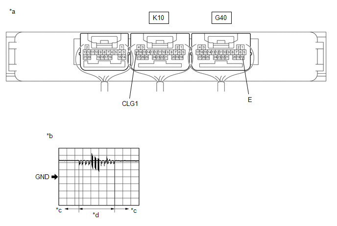
*a | Component with harness connected (Certification ECU (Smart Key ECU Assembly)) |
*b | Waveform 1 |
|
*c | Lock sensor not touched |
*d | Lock sensor touched |
(a) Using an oscilloscope, check the waveform.
OK:
|
Tester Connection | Condition |
Tool Setting | Specified Condition |
|---|---|---|---|
|
K10-17 (CLG1) - G40-18 (E) |
Procedure:
| 5 V/DIV., 40 ms/DIV. |
Pulse generation (See waveform 1) |
*: For details about the entry function detection area, refer to Operation Check.
Click here
| OK | | REPLACE CERTIFICATION ECU (SMART KEY ECU ASSEMBLY) |
| NG | | REPLACE FRONT DOOR OUTSIDE HANDLE ASSEMBLY (FOR DRIVER DOOR) |
DESCRIPTION
If the entry unlock function does not operate for the driver door only, but the entry lock function operates, the request code is being transmitted properly from the driver door. In this case, there may be a problem related to the unlock sensor (connection between the certification ECU (smart key ECU assembly) and front door outside handle assembly (for driver door)).
WIRING DIAGRAM
CAUTION / NOTICE / HINT
NOTICE:
Click here 
Click here
PROCEDURE
|
1. | CHECK POWER DOOR LOCK CONTROL SYSTEM |
(a) When the door control switch on the multiplex network master switch assembly is operated, check that the doors unlock and lock according to the switch operation.
Click here
OK:
Door locks operate normally.
| NG |  |
GO TO POWER DOOR LOCK CONTROL SYSTEM (for Gasoline Model) |
|
| 2. |
READ VALUE USING TECHSTREAM (FL DOOR LOCK POS) |
(a) Connect the Techstream to the DLC3.
(b) Turn the engine switch on (IG).
(c) Turn the Techstream on.
(d) Enter the following menus: Body Electrical / Main Body / Data List.
(e) Read the Data List according to the display on the Techstream.
Body Electrical > Main Body > Data List|
Tester Display | Measurement Item |
Range | Normal Condition |
Diagnostic Note |
|---|---|---|---|---|
|
FL Door Lock Pos | Front door LH unlock detection switch signal |
UNLOCK or LOCK | UNLOCK: Front door LH unlocked LOCK: Front door LH locked |
- |
|
Tester Display |
|---|
| FL Door Lock Pos |
OK:
The Techstream display changes correctly in response to the lock/unlock operation of the driver door.
| NG | | GO TO LIGHTING SYSTEM (for Gasoline Model (Proceed to Door Unlock Detection Switch Circuit)) |
|
| 3. |
READ VALUE USING TECHSTREAM (D-DOOR TOUCH SENSOR) |
(a) Turn the engine switch off.
(b) Open and close the driver door.
(c) With the electrical key transmitter sub-assembly outside of the vehicle, press the lock switch of the electrical key transmitter sub-assembly to lock all of the doors.
(d) Hold the electrical key transmitter sub-assembly at the same height as the door outside handle assembly and approximately 0.3 m (0.984 ft.) from the driver door.
(e) Check that the LED of the electrical key transmitter sub-assembly blinks.
(f) Read the Data List according to the display on the Techstream.
| (g) Touch the unlock sensor on the backside of the front door outside handle assembly (for driver door). HINT: When checking the operation of the unlock sensor again, make sure to perform the procedure from step (a). Body Electrical > Smart Key > Data List
OK: The Techstream display changes correctly in response to the operation of the front door outside handle assembly (for driver door). |
|
| OK | | REPLACE CERTIFICATION ECU (SMART KEY ECU ASSEMBLY) |
|
| 4. |
CHECK HARNESS AND CONNECTOR (CERTIFICATION ECU (SMART KEY ECU ASSEMBLY) - FRONT DOOR OUTSIDE HANDLE ASSEMBLY (FOR DRIVER DOOR)) |
(a) Disconnect the K10 certification ECU (smart key ECU assembly) connector.
(b) Disconnect the I23 front door outside handle assembly (for driver door) connector.
(c) Measure the resistance according to the value(s) in the table below.
Standard Resistance:
|
Tester Connection | Condition |
Specified Condition |
|---|---|---|
|
K10-17 (CLG1) - I23-6 (ANTE1) |
Always | Below 1 Ω |
|
K10-16 (CG1B) - I23-4 (CLGB) |
Always | Below 1 Ω |
|
K10-17 (CLG1) or I23-6 (ANTE1) - Other terminals and body ground |
Always | 10 kΩ or higher |
|
K10-16 (CG1B) or I23-4 (CLGB) - Other terminals and body ground |
Always | 10 kΩ or higher |
(d) Reconnect the I23 front door outside handle assembly (for driver door) connector.
(e) Reconnect the K10 certification ECU (smart key ECU assembly) connector.
| NG | | REPAIR OR REPLACE HARNESS OR CONNECTOR |
|
| 5. |
CHECK FRONT DOOR OUTSIDE HANDLE ASSEMBLY (FOR DRIVER DOOR) (INPUT TO CERTIFICATION ECU (SMART KEY ECU ASSEMBLY)) |
|
*a | Component with harness connected (Certification ECU (Smart Key ECU Assembly)) |
*b | Waveform 1 |
|
*c | Unlock sensor not touched |
*d | Unlock sensor touched |
(a) Using an oscilloscope, check the waveform.
OK:
|
Tester Connection | Condition |
Tool Setting | Specified Condition |
|---|---|---|---|
|
K10-17 (CLG1) - G40-18 (E) |
Procedure:
| 5 V/DIV., 50 ms/DIV. |
Pulse generation (See waveform 1) |
| OK | | REPLACE CERTIFICATION ECU (SMART KEY ECU ASSEMBLY) |
| NG | | REPLACE FRONT DOOR OUTSIDE HANDLE ASSEMBLY (FOR DRIVER DOOR) |
DTC CHECK / CLEAR
CHECK FOR DTC
NOTICE:
When using the Techstream with the engine switch off, connect the Techstream to the DLC3 and turn a courtesy light switch on and off at intervals of 1.5 seconds or less until communication between the Techstream and the vehicle begins. Then select the vehicle type under manual mode and enter the following menus: Body Electrical / Smart Key. While using the Techstream, periodically turn a courtesy light switch on and off at intervals of 1.5 seconds or less to maintain communication between the Techstream and the vehicle.
(a) Connect the Techstream to the DLC3.
(b) Turn the engine switch on (IG).
(c) Turn the Techstream on.
(d) Enter the following menus: Body Electrical / Smart Key / Trouble Codes.
Body Electrical > Smart Key > Trouble Codes(e) Read the DTCs.
NOTICE:
When using the Techstream with the engine switch off, connect the Techstream to the DLC3 and turn a courtesy light switch on and off at intervals of 1.5 seconds or less until communication between the Techstream and the vehicle begins. Then select the vehicle type under manual mode and enter the following menus: Body Electrical / Smart Key. While using the Techstream, periodically turn a courtesy light switch on and off at intervals of 1.5 seconds or less to maintain communication between the Techstream and the vehicle.
CLEAR DTC
(a) Connect the Techstream to the DLC3.
(b) Turn the engine switch on (IG).
(c) Turn the Techstream on.
(d) Enter the following menus: Body Electrical / Smart Key / Trouble Codes.
Body Electrical > Smart Key > Clear DTCs(e) Clear the DTCs.
DESCRIPTION
The smart key system (for Entry Function) uses the wireless door lock buzzer to perform various vehicle exterior warnings. When the conditions of each warning are met, the certification ECU (smart key ECU assembly) sends a buzzer activation request signal to the main body ECU (multiplex network body ECU) via CAN communication and the buzzer sounds.
WIRING DIAGRAM
CAUTION / NOTICE / HINT
NOTICE:
Click here 
Click here
PROCEDURE
|
1. | CHECK CUSTOMIZE SETTING (WIRELESS BUZZER RESP) |
(a) Connect the Techstream to the DLC3.
(b) Turn the engine switch on (IG).
(c) Turn the Techstream on.
(d) Enter the following menus: Customize Setting / Wireless Door Lock.
Wireless Door Lock|
Tester Display | Description |
Default | Setting |
ECU |
|---|---|---|---|---|
| Wireless Buzzer Resp |
Wireless buzzer response |
ON | 0:OFF,1:ON |
Main body ECU (multiplex network body ECU) |
|
Result | Proceed to |
|---|---|
|
"ON" is displayed | A |
|
"OFF" is displayed | B |
| B |
 | PERFORM CUSTOMIZE SETTING |
|
| 2. |
CHECK WIRELESS DOOR LOCK CONTROL SYSTEM |
(a) Check that the function operates normally.
Click here
|
Result | Proceed to |
|---|---|
|
Wireless door lock function operates normally |
A |
| Wireless door lock function does not operate normally |
B |
| B |
| GO TO PROBLEM SYMPTOMS TABLE |
|
| 3. |
READ VALUE USING TECHSTREAM (EACH UNLOCK DETECTION SWITCH) |
(a) Connect the Techstream to the DLC3.
(b) Turn the engine switch on (IG).
(c) Turn the Techstream on.
(d) Enter the following menus: Body Electrical / Main Body / Data List.
(e) Read the Data List according to the display on the Techstream.
Body Electrical > Main Body > Data List|
Tester Display | Measurement Item |
Range | Normal Condition |
Diagnostic Note |
|---|---|---|---|---|
|
FR Door Lock Pos | Front door RH unlock detection switch signal |
UNLOCK or LOCK | UNLOCK: Front door RH unlocked LOCK: Front door RH locked |
- |
| FL Door Lock Pos |
Front door LH unlock detection switch signal |
UNLOCK or LOCK | UNLOCK: Front door LH unlocked LOCK: Front door LH locked |
- |
| RR-Door Lock Pos SW |
Rear door RH unlock detection switch signal |
OFF or ON | OFF: Rear door RH locked ON: Rear door RH unlocked |
- |
| RL-Door Lock Pos SW |
Rear door LH unlock detection switch signal |
OFF or ON | OFF: Rear door LH locked ON: Rear door LH unlocked |
- |
|
Tester Display |
|---|
| FR Door Lock Pos |
|
FL Door Lock Pos |
|
RR-Door Lock Pos SW |
|
RL-Door Lock Pos SW |
OK:
The Techstream display changes correctly in response to the lock/unlock operation.
| NG | | GO TO LIGHTING SYSTEM (Proceed to Door Unlock Detection Switch Circuit) |
|
| 4. |
PERFORM ACTIVE TEST USING TECHSTREAM (WIRELESS BUZZER) |
(a) Connect the Techstream to the DLC3.
(b) Turn the engine switch on (IG).
(c) Turn the Techstream on.
(d) Enter the following menus: Body Electrical / Main Body / Active Test.
(e) Perform Active Test according to the display on the Techstream.
Body Electrical > Main Body > Active Test|
Tester Display | Measurement Item |
Control Range | Diagnostic Note |
|---|---|---|---|
|
Wireless Buzzer | Wireless door lock buzzer |
OFF/ON | - |
|
Tester Display |
|---|
| Wireless Buzzer |
|
Result | Proceed to |
|---|---|
|
Wireless door lock buzzer does not sound |
A |
| Wireless door lock buzzer sounds |
B |
| A |
| GO TO WIRELESS DOOR LOCK CONTROL SYSTEM (NO ANSWER-BACK) |
| B |
| REPLACE CERTIFICATION ECU (SMART KEY ECU ASSEMBLY) |
DESCRIPTION
The smart key system (for Entry Function) uses the buzzer in the combination meter assembly (meter ECU) to perform various vehicle interior warnings. When the conditions of each warning are met, the certification ECU (smart key ECU assembly) sends a buzzer activation request signal to the combination meter assembly via CAN communication and the buzzer sounds.
CAUTION / NOTICE / HINT
NOTICE:
Click here 
Click here
PROCEDURE
|
1. | CHECK ENTRY LOCK OPERATION |
(a) Check that the function operates normally.
Click here
|
Result | Proceed to |
|---|---|
|
Entry function operates normally |
A |
| Entry function does not operate normally |
B |
| A |
 | GO TO METER / GAUGE SYSTEM |
| B |
| GO TO OTHER PROBLEM |
DESCRIPTION
If the entry lock and unlock functions do not operate for the front passenger door only, the request code may not be being transmitted from the front passenger door or the front door outside handle assembly (for front passenger door) (touch sensor) may be malfunctioning. If the entry functions for other doors operate properly, communication between the electrical key transmitter sub-assembly and electrical key and tire pressure monitoring system receiver assembly is normal. In this case, there may be a problem with request code transmission (communication between the certification ECU (smart key ECU assembly) and front door outside handle assembly (for front passenger door) (electrical key antenna)), or there may be wave interference.
WIRING DIAGRAM

CAUTION / NOTICE / HINT
NOTICE:
Click here
Click here
HINT:
|
Tester Display |
|---|
| Operation History |
PROCEDURE
| 1. |
CHECK POWER DOOR LOCK CONTROL SYSTEM |
(a) When the door control switch on the multiplex network master switch assembly is operated, check that the doors unlock and lock according to the switch operation.
Click here
OK:
Door locks operate normally.
| NG | |
GO TO POWER DOOR LOCK CONTROL SYSTEM |
|
| 2. |
CHECK FOR DTC |
(a) Check for DTCs.
Body Electrical > Smart Key > Trouble Codes|
Result | Proceed to |
|---|---|
|
DTCs are not output | A |
|
DTCs are output | B |
| B |
| GO TO DIAGNOSTIC TROUBLE CODE CHART |
|
| 3. |
CHECK WAVE ENVIRONMENT |
| (a) Bring the electrical key transmitter sub-assembly approximately 0.3 m (0.984 ft.) from the front door outside handle assembly (for front passenger door) and perform an entry function check. Click here
|
|
| Result |
Proceed to |
|---|---|
| Entry function does not operate normally |
A |
| Entry function operates normally |
B |
| B |
| AFFECTED BY WAVE INTERFERENCE |
|
| 4. |
READ VALUE USING TECHSTREAM (P-DOOR TOUCH SENSOR) |
(a) Turn the engine switch off.
(b) Open and close the front passenger door.
(c) With the electrical key transmitter sub-assembly outside of the vehicle, press the lock switch of the electrical key transmitter sub-assembly to lock all of the doors.
(d) Hold the electrical key transmitter sub-assembly at the same height as the door outside handle assembly and approximately 0.3 m (0.984 ft.) from the front passenger door.
(e) Check that the LED of the electrical key transmitter sub-assembly blinks.
(f) Read the Data List according to the display on the Techstream.
| (g) Touch the unlock sensor on the backside of the front door outside handle assembly (for front passenger door). HINT: When checking the operation of the unlock sensor again, make sure to perform the procedure from step (a). Body Electrical > Smart Key > Data List
OK: The Techstream display changes correctly in response to the operation of the front door outside handle assembly (for front passenger door). |
|
| NG | | GO TO STEP 7 |
|
| 5. |
READ VALUE USING TECHSTREAM (P-DOOR TRIGGER SWITCH) |
(a) Turn the engine switch off.
(b) Open and close the front passenger door.
(c) Hold the electrical key transmitter sub-assembly at the same height as the door outside handle assembly and approximately 0.3 m (0.984 ft.) from the front passenger door.
(d) Read the Data List according to the display on the Techstream.
| (e) Touch the lock sensor of the front door outside handle assembly (for driver door). HINT:
HINT: When checking the operation of the entry lock function several times, it can be operated up to 2 times consecutively. To operate the function 3 times or more consecutively, the doors need to be unlocked once. However, this is only for the entry lock function, other door lock operations, such as a wireless door lock operation can be performed consecutively. OK: The Techstream display changes correctly in response to the operation of the front door outside handle assembly (for front passenger door). |
|
| NG | | GO TO STEP 7 |
|
| 6. |
CHECK KEY DIAGNOSTIC MODE |
(a) Check the following antenna in key diagnostic mode.
Body Electrical > Smart Key > Utility|
Tester Display |
|---|
| Communication Check(Key Diag Mode) |
(b) Select either channel 1 or channel 2 and perform key diagnostic mode inspection for each channel.
| (1) Check the electrical key antenna (for front passenger door): When the electrical key transmitter sub-assembly is brought within 0.7 to 1 m (2.30 to 3.28 ft.) of the front door outside handle assembly (for front passenger door), check that the wireless buzzer sounds. HINT:
|
|
|
Result | Proceed to |
|---|---|
|
Wireless buzzer does not sound |
A |
| Wireless buzzer sounds |
B |
| B |
| REPLACE CERTIFICATION ECU (SMART KEY ECU ASSEMBLY) |
|
| 7. |
CHECK HARNESS AND CONNECTOR (CERTIFICATION ECU (SMART KEY ECU ASSEMBLY) - FRONT DOOR OUTSIDE HANDLE ASSEMBLY (FOR FRONT PASSENGER DOOR)) |
(a) Disconnect the K10 certification ECU (smart key ECU assembly) connector.
(b) Disconnect the I7 front door outside handle assembly (for front passenger door) connector.
(c) Measure the resistance according to the value(s) in the table below.
Standard Resistance:
|
Tester Connection | Condition |
Specified Condition |
|---|---|---|
|
K10-15 (CLG2) - I7-6 (ANTE2) |
Always | Below 1 Ω |
|
K10-14 (CG2B) - I7-4 (CLGB) |
Always | Below 1 Ω |
|
K10-15 (CLG2) or I7-6 (ANTE2) - Other terminals and body ground |
Always | 10 kΩ or higher |
|
K10-14 (CG2B) or I7-4 (CLGB) - Other terminals and body ground |
Always | 10 kΩ or higher |
(d) Reconnect the K10 certification ECU (smart key ECU assembly) connector.
| NG | | REPAIR OR REPLACE HARNESS OR CONNECTOR |
|
| 8. |
CHECK CERTIFICATION ECU (SMART KEY ECU ASSEMBLY) (OUTPUT TO FRONT PASSENGER DOOR ELECTRICAL KEY ANTENNA) |
| (a) Using an oscilloscope, check the waveform. OK:
*: For details about the entry function detection area, refer to Operation Check. Click here |
|
| NG | | REPLACE CERTIFICATION ECU (SMART KEY ECU ASSEMBLY) |
|
| 9. |
CHECK ENTRY LOCK OPERATION |
(a) Connect all connectors and check that the function operates normally.
Click here
|
Result | Proceed to |
|---|---|
|
Entry function does not operate normally |
A |
| Entry function operates normally |
B |
| B |
| END (CONNECTOR WAS NOT CONNECTED SECURELY) |
|
| 10. |
REPLACE FRONT DOOR OUTSIDE HANDLE ASSEMBLY (FOR FRONT PASSENGER DOOR) |
(a) Replace the front door outside handle assembly (for front passenger door) with a new one or the front door outside handle assembly (for driver door) if it is functioning properly.
Click here
|
| 11. |
CHECK ENTRY LOCK OPERATION |
(a) Check that the function operates normally.
Click here
|
Result | Proceed to |
|---|---|
|
Entry function operates normally |
A |
| Entry function does not operate normally |
B |
| A |
| END (FRONT DOOR OUTSIDE HANDLE ASSEMBLY (FOR FRONT PASSENGER DOOR) WAS DEFECTIVE) |
| B |
| REPLACE CERTIFICATION ECU (SMART KEY ECU ASSEMBLY) |
DESCRIPTION
If the entry lock function does not operate for the front passenger door only, but the entry unlock function operates, the request code is being transmitted properly from the for passenger door. In this case, there may be a problem related to the lock sensor (connection between the certification ECU (smart key ECU assembly) and front door outside handle assembly (for front passenger door)).
WIRING DIAGRAM

CAUTION / NOTICE / HINT
NOTICE:
Click here 
Click here
PROCEDURE
|
1. | CHECK POWER DOOR LOCK CONTROL SYSTEM |
(a) When the door control switch on the multiplex network master switch assembly is operated, check that the doors unlock and lock according to the switch operation.
Click here
OK:
Door locks operate normally.
| NG |  | GO TO POWER DOOR LOCK CONTROL SYSTEM |
|
| 2. |
READ VALUE USING TECHSTREAM (P-DOOR TRIGGER SWITCH) |
(a) Turn the engine switch off.
(b) Open and close the front passenger door.
(c) Hold the electrical key transmitter sub-assembly at the same height as the door outside handle assembly and approximately 0.3 m (0.984 ft.) from the front passenger door.
(d) Read the Data List according to the display on the Techstream.
| (e) Touch the lock sensor of the front door outside handle assembly (for front passenger door). HINT:
HINT: When checking the operation of the entry lock function several times, it can be operated up to 2 times consecutively. To operate the function 3 times or more consecutively, the doors need to be unlocked once. However, this is only for the entry lock function, other door lock operations, such as a wireless door lock operation can be performed consecutively. OK: The Techstream display changes correctly in response to the operation of the front door outside handle assembly (for front passenger door). |
|
| OK | | REPLACE CERTIFICATION ECU (SMART KEY ECU ASSEMBLY) |
|
| 3. |
CHECK HARNESS AND CONNECTOR (CERTIFICATION ECU (SMART KEY ECU ASSEMBLY) - FRONT DOOR OUTSIDE HANDLE ASSEMBLY (FOR FRONT PASSENGER DOOR)) |
(a) Disconnect the K10 certification ECU (smart key ECU assembly) connector.
(b) Disconnect the I7 front door outside handle assembly (for front passenger door) connector.
(c) Measure the resistance according to the value(s) in the table below.
Standard Resistance:
|
Tester Connection | Condition |
Specified Condition |
|---|---|---|
|
K10-15 (CLG2) - I7-6 (ANTE2) |
Always | Below 1 Ω |
|
K10-14 (CG2B) - I7-4 (CLGB) |
Always | Below 1 Ω |
|
K10-15 (CLG2) or I7-6 (ANTE2) - Other terminals and body ground |
Always | 10 kΩ or higher |
|
K10-14 (CG2B) or I7-4 (CLGB) - Other terminals and body ground |
Always | 10 kΩ or higher |
(d) Reconnect the I7 front door outside handle assembly (for front passenger door) connector.
(e) Reconnect the K10 certification ECU (smart key ECU assembly) connector.
| NG | | REPAIR OR REPLACE HARNESS OR CONNECTOR |
|
| 4. |
CHECK FRONT DOOR OUTSIDE HANDLE ASSEMBLY (FOR FRONT PASSENGER DOOR) (INPUT TO CERTIFICATION ECU (SMART KEY ECU ASSEMBLY)) |

|
*a | Component with harness connected (Certification ECU (Smart Key ECU Assembly)) |
*b | Waveform 1 |
|
*c | Lock sensor not touched |
*d | Lock sensor touched |
(a) Using an oscilloscope, check the waveform.
OK:
|
Tester Connection | Condition |
Tool Setting | Specified Condition |
|---|---|---|---|
|
K10-15 (CLG2) - G40-18 (E) |
Procedure:
| 5 V/DIV., 40 ms/DIV. |
Pulse generation (See waveform 1) |
*: For details about the entry function detection area, refer to Operation Check.
Click here
| OK | | REPLACE CERTIFICATION ECU (SMART KEY ECU ASSEMBLY) |
| NG | | REPLACE FRONT DOOR OUTSIDE HANDLE ASSEMBLY (FOR FRONT PASSENGER DOOR) |
DESCRIPTION
If the entry unlock function does not operate for the front passenger door only, but the entry lock function operates, the request code is being transmitted properly from the front passenger door. In this case, there may be a problem related to the unlock sensor (connection between the certification ECU (smart key ECU assembly) and front door outside handle assembly (for front passenger door)).
WIRING DIAGRAM

CAUTION / NOTICE / HINT
NOTICE:
Click here 
Click here
PROCEDURE
|
1. | CHECK POWER DOOR LOCK CONTROL SYSTEM |
(a) When the door control switch on the multiplex network master switch assembly is operated, check that the doors unlock and lock according to the switch operation.
Click here
OK:
Door locks operate normally.
| NG |  | GO TO POWER DOOR LOCK CONTROL SYSTEM |
|
| 2. |
READ VALUE USING TECHSTREAM (FR DOOR LOCK POS) |
(a) Connect the Techstream to the DLC3.
(b) Turn the engine switch on (IG).
(c) Turn the Techstream on.
(d) Enter the following menus: Body Electrical / Main Body / Data List.
(e) Read the Data List according to the display on the Techstream.
Body Electrical > Main Body > Data List|
Tester Display | Measurement Item |
Range | Normal Condition |
Diagnostic Note |
|---|---|---|---|---|
|
FR Door Lock Pos | Front door RH unlock detection switch signal |
UNLOCK or LOCK | UNLOCK: Front door RH unlocked LOCK: Front door RH locked |
- |
|
Tester Display |
|---|
| FR Door Lock Pos |
OK:
The Techstream display changes correctly in response to the lock/unlock operation of the front passenger door.
| NG | | GO TO LIGHTING SYSTEM (Proceed to Door Unlock Detection Switch Circuit) |
|
| 3. |
READ VALUE USING TECHSTREAM (P-DOOR TOUCH SENSOR) |
(a) Turn the engine switch off.
(b) Open and close the front passenger door.
(c) With the electrical key transmitter sub-assembly outside of the vehicle, press the lock switch of the electrical key transmitter sub-assembly to lock all of the doors.
(d) Hold the electrical key transmitter sub-assembly at the same height as the door outside handle assembly and approximately 0.3 m (0.984 ft.) from the front passenger door.
(e) Check that the LED of the electrical key transmitter sub-assembly blinks.
(f) Read the Data List according to the display on the Techstream.
| (g) Touch the unlock sensor on the backside of the front door outside handle assembly (for front passenger door). HINT: When checking the operation of the unlock sensor again, make sure to perform the procedure from step (a). Body Electrical > Smart Key > Data List
OK: The Techstream display changes correctly in response to the operation of the front door outside handle assembly (for front passenger door). |
|
| OK | | REPLACE CERTIFICATION ECU (SMART KEY ECU ASSEMBLY) |
|
| 4. |
CHECK HARNESS AND CONNECTOR (CERTIFICATION ECU (SMART KEY ECU ASSEMBLY) - FRONT DOOR OUTSIDE HANDLE ASSEMBLY (FOR FRONT PASSENGER DOOR)) |
(a) Disconnect the K10 certification ECU (smart key ECU assembly) connector.
(b) Disconnect the I7 front door outside handle assembly (for front passenger door) connector.
(c) Measure the resistance according to the value(s) in the table below.
Standard Resistance:
|
Tester Connection | Condition |
Specified Condition |
|---|---|---|
|
K10-15 (CLG2) - I7-6 (ANTE2) |
Always | Below 1 Ω |
|
K10-14 (CG2B) - I7-4 (CLGB) |
Always | Below 1 Ω |
|
K10-15 (CLG2) or I7-6 (ANTE2) - Other terminals and body ground |
Always | 10 kΩ or higher |
|
K10-14 (CG2B) or I7-4 (CLGB) - Other terminals and body ground |
Always | 10 kΩ or higher |
(d) Reconnect the I7 front door outside handle assembly (for front passenger door) connector.
(e) Reconnect the K10 certification ECU (smart key ECU assembly) connector.
| NG | | REPAIR OR REPLACE HARNESS OR CONNECTOR |
|
| 5. |
CHECK FRONT DOOR OUTSIDE HANDLE ASSEMBLY (FOR FRONT PASSENGER DOOR) (INPUT TO CERTIFICATION ECU (SMART KEY ECU ASSEMBLY)) |

|
*a | Component with harness connected (Certification ECU (Smart Key ECU Assembly)) |
*b | Waveform 1 |
|
*c | Unlock sensor not touched |
*d | Unlock sensor touched |
(a) Using an oscilloscope, check the waveform.
OK:
|
Tester Connection | Condition |
Tool Setting | Specified Condition |
|---|---|---|---|
|
K10-15 (CLG2) - G40-18 (E) |
Procedure:
| 5 V/DIV., 50 ms/DIV. |
Pulse generation (See waveform 1) |
| OK | | REPLACE CERTIFICATION ECU (SMART KEY ECU ASSEMBLY) |
| NG | | REPLACE FRONT DOOR OUTSIDE HANDLE ASSEMBLY (FOR FRONT PASSENGER DOOR) |
CAUTION / NOTICE / HINT
CAUTION:
Make sure to check the items listed below before proceeding with troubleshooting.
HINT:
PROCEDURE
|
1. | VEHICLE BROUGHT TO WORKSHOP |
(a) Confirm how vehicle was brought to workshop
HINT:
The malfunction location may be narrowed down by confirming whether the vehicle was driven or towed.
| NEXT |  | GO TO SMART KEY SYSTEM (for Start Function, Gasoline Model) |
DESCRIPTION
If the entry luggage compartment lock-in prevention function does not operate, there may be a problem with the communication between the No. 1 indoor electrical key antenna assembly (inside luggage compartment) and electrical key transmitter sub-assembly, wave interference or a malfunction in the certification ECU (smart key ECU assembly).
WIRING DIAGRAM

CAUTION / NOTICE / HINT
NOTICE:
Click here
Click here
PROCEDURE
|
1. | CHECK ENTRY LUGGAGE COMPARTMENT OPEN OPERATION |
(a) Connect all connectors and check that the entry luggage compartment open function operates.
Click here
|
Result | Proceed to |
|---|---|
|
Luggage open function operates normally |
A |
| Luggage open function does not operate normally |
B |
| B |
| GO TO OTHER PROBLEM (Proceed to Luggage Compartment Door Entry Unlock Function does not Operate when Key is Outside Luggage Compartment) |
|
| 2. |
CHECK WAVE ENVIRONMENT |
| (a) Bring the electrical key transmitter sub-assembly near the No. 1 indoor electrical key antenna assembly (inside luggage compartment), and check that the entry luggage compartment lock-in prevention function operates. NOTICE: In order to prevent the electrical key transmitter sub-assembly from being locked inside the vehicle, perform this inspection with the window of a door open. HINT:
|
|
|
Result | Proceed to |
|---|---|
|
Entry functions does not operate normally |
A |
| Entry functions operate normally |
B |
| B |
| AFFECTED BY WAVE INTERFERENCE |
|
| 3. |
CHECK KEY DIAGNOSTIC MODE |
(a) Check the following antenna in key diagnostic mode.
Body Electrical > Smart Key > Utility|
Tester Display |
|---|
| Communication Check(Key Diag Mode) |
| (b) Select either channel 1 or channel 2 and inspect key diagnostic mode for each channel. (1) Check the No. 1 indoor electrical key antenna assembly (inside luggage compartment): When the electrical key transmitter sub-assembly is at either inspection point, check that the wireless buzzer sounds. HINT:
|
|
|
Result | Proceed to |
|---|---|
|
Wireless buzzer does not sound |
A |
| Wireless buzzer sounds |
B |
| B |
| REPLACE CERTIFICATION ECU (SMART KEY ECU ASSEMBLY) |
|
| 4. |
CHECK HARNESS AND CONNECTOR (CERTIFICATION ECU (SMART KEY ECU ASSEMBLY) - NO. 1 INDOOR ELECTRICAL KEY ANTENNA ASSEMBLY (INSIDE LUGGAGE COMPARTMENT)) |
(a) Disconnect the K10 certification ECU (smart key ECU assembly) connector.
(b) Disconnect the K13 No. 1 indoor electrical key antenna assembly (inside luggage compartment) connector.
(c) Measure the resistance according to the value(s) in the table below.
Standard Resistance:
|
Tester Connection | Condition |
Specified Condition |
|---|---|---|
|
K10-11 (CLG7) - K13-1 (ANTE7) |
Always | Below 1 Ω |
|
K10-10 (CG7B) - K13-3 (CLGB) |
Always | Below 1 Ω |
|
K10-11 (CLG7) or K13-1 (ANTE7) - Other terminals and body ground |
Always | 10 kΩ or higher |
|
K10-10 (CG7B) or K13-3 (CLGB) - Other terminals and body ground |
Always | 10 kΩ or higher |
(d) Reconnect the K10 certification ECU (smart key ECU assembly) connector.
| NG | | REPAIR OR REPLACE HARNESS OR CONNECTOR |
|
| 5. |
CHECK CERTIFICATION ECU (SMART KEY ECU ASSEMBLY) (OUTPUT TO NO. 1 INDOOR ELECTRICAL KEY ANTENNA ASSEMBLY (INSIDE LUGGAGE COMPARTMENT)) |
| (a) Using an oscilloscope, check the wave form. OK:
|
|
| NG | | REPLACE CERTIFICATION ECU (SMART KEY ECU ASSEMBLY) |
|
| 6. |
REPLACE NO. 1 INDOOR ELECTRICAL KEY ANTENNA ASSEMBLY (INSIDE LUGGAGE COMPARTMENT) |
(a) Replace the No. 1 indoor electrical key antenna assembly (inside luggage compartment).
Click here
|
| 7. |
CHECK KEY LOCK-IN PREVENTION FUNCTION |
(a) Check that the entry luggage compartment lock-in prevention function operates normally.
Click here
OK:
Entry luggage compartment lock-in prevention function operates normally.
| OK | | END (NO. 1 INDOOR ELECTRICAL KEY ANTENNA ASSEMBLY (INSIDE LUGGAGE COMPARTMENT) WAS DEFECTIVE) |
| NG | | REPLACE CERTIFICATION ECU (SMART KEY ECU ASSEMBLY) |
DESCRIPTION
If the entry luggage compartment door open function does not operate, there may be a malfunction in the luggage electrical key switch circuit or certification ECU (smart key ECU assembly), which receives a signal from the luggage electrical key switch circuit, or a communication error between the vehicle (electrical key antenna (outside luggage compartment)) and electrical key transmitter sub-assembly.
WIRING DIAGRAM

CAUTION / NOTICE / HINT
NOTICE:
Click here
Click here
HINT:
|
Tester Display |
|---|
| Operation History |
PROCEDURE
| 1. |
READ VALUE USING TECHSTREAM (LUGGAGE COMPARTMENT DOOR OPEN MODE) |
(a) Connect the Techstream to the DLC3.
(b) Turn the engine switch on (IG).
(c) Turn the Techstream on.
(d) Enter the following menus: Body Electrical / Smart Key / Data List.
(e) Read the Data List according to the display on the Techstream.
Body Electrical > Smart Key > Data List|
Tester Display | Measurement Item |
Range | Normal Condition |
Diagnostic Note |
|---|---|---|---|---|
|
Trunk Open Mode | Entry luggage compartment open mode |
OFF or ON | Customize setting displayed |
- |
|
Tester Display |
|---|
| Trunk Open Mode |
|
Result | Proceed to |
|---|---|
|
Trunk Open Mode is ON |
A |
| Trunk Open Mode is OFF |
B |
| B |
| PERFORM CUSTOMIZE SETTING (Proceed to Customize Parameters) |
|
| 2. |
CHECK LUGGAGE COMPARTMENT DOOR OPENER SYSTEM |
(a) Operate the luggage compartment door opening switch assembly in the vehicle and check that the luggage compartment door opens.
Click here
|
Result | Proceed to |
|---|---|
|
The luggage compartment door opens |
A |
| The luggage compartment door does not open |
B |
| B |
| GO TO LUGGAGE COMPARTMENT DOOR OPENER SYSTEM |
|
| 3. |
READ VALUE USING TECHSTREAM (TR/B-DOOR UNLOCK SW) |
(a) Connect the Techstream to the DLC3.
(b) Turn the engine switch on (IG).
(c) Turn the Techstream on.
(d) Enter the following menus: Body Electrical / Smart Key / Data List.
(e) Read the Data List according to the display on the Techstream.
Body Electrical > Smart Key > Data List|
Tester Display | Measurement Item |
Range | Normal Condition |
Diagnostic Note |
|---|---|---|---|---|
|
Tr/B-Door Unlock SW | Luggage electrical key switch |
OFF or ON | OFF: Luggage electrical key switch not pushed ON: Luggage electrical key switch pushed |
- |
|
Tester Display |
|---|
| Tr/B-Door Unlock SW |
OK:
The Techstream display changes correctly in response to the operation of the luggage electrical key switch.
| NG | | GO TO STEP 9 |
|
| 4. |
CHECK WAVE ENVIRONMENT |
| (a) Bring the electrical key transmitter sub-assembly approximately 0.3 m (0.984 ft.) from the electrical key antenna (outside luggage compartment) and perform an entry luggage compartment open function check. HINT:
OK: Entry functions operate normally. |
|
| OK | | AFFECTED BY WAVE INTERFERENCE |
|
| 5. |
CHECK KEY DIAGNOSTIC MODE |
(a) Check the following antenna in key diagnostic mode.
Body Electrical > Smart Key > Utility|
Tester Display |
|---|
| Communication Check(Key Diag Mode) |
| (b) When the electrical key transmitter sub-assembly is brought within 0.7 to 1 m (2.30 to 3.28 ft.) of the electrical key antenna (outside luggage compartment), check that the wireless buzzer sounds. HINT:
OK: Wireless buzzer sounds. |
|
| OK | | REPLACE CERTIFICATION ECU (SMART KEY ECU ASSEMBLY) |
|
| 6. |
CHECK HARNESS AND CONNECTOR (CERTIFICATION ECU (SMART KEY ECU ASSEMBLY) - ELECTRICAL KEY ANTENNA (OUTSIDE LUGGAGE COMPARTMENT)) |
(a) Disconnect the K10 certification ECU (smart key ECU assembly) connector.
(b) Disconnect the P2 electrical key antenna (outside luggage compartment) connector.
(c) Measure the resistance according to the value(s) in the table below.
Standard Resistance:
|
Tester Connection | Condition |
Specified Condition |
|---|---|---|
|
K10-13 (CLG8) - P2-2 (ANTE8) |
Always | Below 1 Ω |
|
K10-12 (CG8B) - P2-1 (CLGB) |
Always | Below 1 Ω |
|
K10-13 (CLG8) or P2-2 (ANTE8) - Other terminals and body ground |
Always | 10 kΩ or higher |
|
K10-12 (CG8B) or P2-1 (CLGB) - Other terminals and body ground |
Always | 10 kΩ or higher |
(d) Reconnect the K10 certification ECU (smart key ECU assembly) connector.
(e) Reconnect the P2 electrical key antenna (outside luggage compartment) connector.
| NG | | REPAIR OR REPLACE HARNESS OR CONNECTOR |
|
| 7. |
CHECK CERTIFICATION ECU (SMART KEY ECU ASSEMBLY) (OUTPUT TO ELECTRICAL KEY ANTENNA (OUTSIDE LUGGAGE COMPARTMENT)) |

|
*a | Component with harness connected (Certification ECU (Smart Key ECU Assembly)) |
*b | Waveform 1 |
(a) Using an oscilloscope, check the waveform.
OK:
|
Tester Connection | Condition |
Tool Setting | Specified Condition |
|---|---|---|---|
|
K10-13 (CLG8) - G40-18 (E) | Procedure:
| 2 V/DIV., 500 ms/DIV. |
Pulse generation (See waveform 1) |
|
K10-12 (CG8B) - G40-18 (E) | Procedure:
| 2 V/DIV., 500 ms/DIV. |
Pulse generation (See waveform 1) |
| NG | | REPLACE ELECTRICAL KEY ANTENNA (OUTSIDE LUGGAGE COMPARTMENT) |
|
| 8. |
CHECK ENTRY LUGGAGE COMPARTMENT OPEN OPERATION |
(a) Connect all connectors and check that the entry luggage compartment open function operates.
Click here
|
Result | Proceed to |
|---|---|
|
Luggage open function operates normally |
A |
| Luggage open function does not operate normally |
B |
| A |
| END (CONNECTOR WAS NOT CONNECTED SECURELY) |
| B |
| REPLACE CERTIFICATION ECU (SMART KEY ECU ASSEMBLY) |
| 9. |
INSPECT LUGGAGE ELECTRICAL KEY SWITCH |
(a) Remove the luggage electrical key switch.
Click here
(b) Inspect the luggage electrical key switch.
Click here
| NG | | REPLACE LUGGAGE ELECTRICAL KEY SWITCH |
|
| 10. |
CHECK HARNESS AND CONNECTOR (CERTIFICATION ECU (SMART KEY ECU ASSEMBLY) - LUGGAGE ELECTRICAL KEY SWITCH) |
(a) Disconnect the K10 certification ECU (smart key ECU assembly) connector.
(b) Disconnect the P1 luggage electrical key switch connector.
(c) Measure the resistance according to the value(s) in the table below.
Standard Resistance:
|
Tester Connection | Condition |
Specified Condition |
|---|---|---|
|
K10-26 (TSW5) - P1-2 |
Always | Below 1 Ω |
|
P1-1 - Body ground | Always |
Below 1 Ω |
|
K10-26 (TSW5) or P1-2 - Other terminals and body ground |
Always | 10 kΩ or higher |
| NG | | REPAIR OR REPLACE HARNESS OR CONNECTOR |
|
| 11. |
CHECK ENTRY LUGGAGE COMPARTMENT OPEN OPERATION |
(a) Connect all connectors and check that the entry luggage compartment open function operates.
Click here
|
Result | Proceed to |
|---|---|
|
Luggage open function operates normally |
A |
| Luggage open function does not operate normally |
B |
| A |
| END (CONNECTOR WAS NOT CONNECTED SECURELY) |
| B |
| REPLACE CERTIFICATION ECU (SMART KEY ECU ASSEMBLY) |
OPERATION CHECK
CHECK CUSTOMIZE PARAMETERS
NOTICE:
The operation check below is based on the non-customized initial condition of the vehicle.
Click here 
CHECK THE ENTRY UNLOCK FUNCTION
(a) Check the entry unlock function (driver door, front passenger door).
(1) Perform a wireless lock door operation to lock the door, touch the unlock sensor built into the backside of the front door outside handle assembly of the driver door while carrying the electrical key transmitter sub-assembly and check that the door unlocks.
(2) Inspect the entry unlock detection area. Hold the electrical key transmitter sub-assembly at the same height as the door outside handle assembly and approximately 0.7 to 1 m (2.30 to 3.28 ft.) from the vehicle as shown in the illustration and check that the LED (red) of the electrical key transmitter sub-assembly blinks.
|
*a | 0.7 to 1 m (2.30 to 3.28 ft.) |
(3) With the system in unlock standby mode, grasp the front door outside handle assembly (for driver door) and check that the door unlocks.
HINT:
(4) Check the unlock response sensitivity. With the system in unlock standby mode, touch the area shown in the illustration and check that the door unlocks.
NOTICE:
If the sensor is touched too quickly or released too slowly, the sensor may not react and the door will not unlock.

|
*a | Unlock Sensor (Backside) |
HINT:
Inspect the front passenger door using the same procedure.
CHECK THE ENTRY LOCK FUNCTION
(a) Check the entry lock function (driver door, front passenger door).
NOTICE:
If the electrical key transmitter sub-assembly is in the vehicle but outside the detection area (on the instrument panel, in the glove box, on the floor) and a door lock operation is performed, the key lock-in prevention function will not operate and the electrical key transmitter sub-assembly will be locked inside the vehicle.
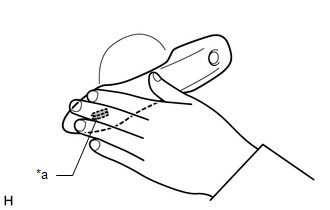
|
*a | Lock Sensor |
(1) With the door closed and unlocked, touch the lock sensor of the front door outside handle assembly of the driver door while carrying the electrical key transmitter sub-assembly and check that the door locks.
HINT:
(2) Inspect the entry lock operating range. Hold the electrical key transmitter sub-assembly approximately 0.7 to 1 m (2.30 to 3.28 ft.) below the bottom edge of the door glass and approximately 0.3 m (0.984 ft.) from the vehicle as shown in the illustration, touch the lock sensor and check that the door locks.
HINT:
|
*a | 0.7 to 1 m (2.30 to 3.28 ft.) |
CHECK ENTRY LUGGAGE DOOR OPEN FUNCTION
(a) Check the entry luggage compartment open function (luggage electrical key switch).
(1) Perform a wireless lock operation to lock the doors, operate of the luggage electrical key switch while carrying the electrical key transmitter sub-assembly and check that the luggage compartment door opens.
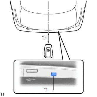
|
*1 | Luggage Electrical Key Switch |
|
*a | 0.7 to 1 m (2.30 to 3.28 ft.) |
(2) Inspect the entry luggage compartment open operating range. While standing at the rear of the vehicle, hold the electrical key transmitter sub-assembly so that it is facing the direction shown in the above illustration at the same height as the luggage electrical key switch and approximately 0.7 to 1 m (2.30 to 3.28 ft.) from the vehicle, press the luggage electrical key switch and check that the luggage compartment door opens.
CHECK PUSH-BUTTON START FUNCTION
Click here
CHECK KEY LOCK-IN PREVENTION FUNCTION (VEHICLE INTERIOR)
NOTICE:
In order to prevent the electrical key transmitter sub-assembly from being locked inside the vehicle, perform this inspection with the window of a door open.
(a) Check the key lock-in prevention function (vehicle interior).
(1) Turn the engine switch off.
(2) Place the electrical key transmitter sub-assembly on a front or rear seat.
(3) Close all of the doors and make sure they are unlocked.
(4) Touch a door lock sensor and check that the doors do not lock and the key lock-in prevention function buzzer (external) sounds for approximately 5 seconds.
CHECK KEY LOCK-IN PREVENTION FUNCTION (IN LUGGAGE COMPARTMENT)
NOTICE:
In order to prevent the electrical key transmitter sub-assembly from being locked inside the vehicle, perform this inspection with the window of a door open.
If the electrical key transmitter sub-assembly is in any of the following locations, the key lock-in prevention function may not operate:
(a) Check the key lock-in prevention function (in luggage compartment).
(1) Place the electrical key transmitter sub-assembly in the luggage compartment with all doors locked. Check that: 1) closing the luggage compartment door triggers the wireless buzzer (which lasts approximately 2 seconds), and 2) pressing the luggage electrical key switch opens the luggage compartment door.
(2) Inspect the key lock-in prevention detection area. Pay attention to the direction of the electrical key transmitter sub-assembly shown in the illustration. When the electrical key transmitter sub-assembly is in either of the 2 locations in the illustration, check that: 1) closing the luggage compartment door sounds the wireless buzzer, and 2) pressing the luggage electrical key switch opens the luggage compartment door.
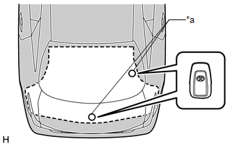
|
*a | Inspection Point |
HINT:
Perform the inspection for both inspection points.
(3) Inspect the key lock-in prevention detection area and the electrical key and tire pressure monitoring system receiver assembly for wave leaks. Hold the electrical key transmitter sub-assembly at the same height as the lower edge of the luggage compartment door aligning it with the center of the rear of the vehicle. Pay attention to the direction and position of the electrical key transmitter sub-assembly shown in the illustration.

|
*a | 0.1 m or more (0.328 ft. or more) |
HINT:
CHECK ANSWER-BACK FUNCTION
(a) Check the answer-back function (hazard warning light flashing and buzzer sounding).
|
Entry Operation | Hazard Warning Light |
Wireless Buzzer |
|---|---|---|
|
Entry Lock | Flashes once |
Sounds once |
|
Entry Unlock | Flashes twice |
Sounds twice |
CHECK TRANSMITTER BATTERY SAVING MODE FUNCTION
Click here
CHECK ENTRY CANCEL FUNCTION
Click here
KEY DIAGNOSTIC MODE (Using Techstream)
HINT:
(a) Enter the following menus: Body Electrical / Smart Key / Utility / Communication Check(Key Diag Mode).
Body Electrical > Smart Key > Utility|
Tester Display |
|---|
| Communication Check(Key Diag Mode) |
(b) Inspect the appropriate item according to the following table.
|
Tester Display | Inspection Item |
|---|---|
|
[CH1/CH2] Overhead + Driver Side*1 |
Front door outside handle assembly (electrical key antenna) (for driver door) |
|
[CH1] Overhead + Driver Side*1 | |
|
[CH2] Overhead + Driver Side*1 | |
|
[CH1/CH2] Overhead + Passenger Side*2 |
Front door outside handle assembly (electrical key antenna) (for front passenger door) |
|
[CH1] Overhead + Passenger Side*2 | |
|
[CH2] Overhead + Passenger Side*2 | |
|
[CH1/CH2] Overhead + Front Room*3 |
No. 1 indoor electrical key antenna assembly (front floor) |
|
[CH1] Overhead + Front Room*3 | |
|
[CH2] Overhead + Front Room*3 | |
|
[CH1/CH2] Overhead + Rear Room*4 |
No. 1 indoor electrical key antenna assembly (rear floor) |
|
[CH1] Overhead + Rear Room*4 | |
|
[CH2] Overhead + Rear Room*4 | |
|
[CH1/CH2] Overhead + Luggage*5 |
Electrical key antenna (outside luggage compartment) |
|
[CH1] Overhead + Luggage*5 | |
|
[CH2] Overhead + Luggage*5 | |
|
[CH1/CH2] Luggage + Luggage (inside)*6 |
No. 1 indoor electrical key antenna assembly (inside luggage) |
|
[CH1] Luggage + Luggage (inside)*6 | |
|
[CH2] Luggage + Luggage (inside)*6 | |
|
[CH1/CH2] Luggage + Luggage*7 |
Electrical key antenna (outside luggage compartment) |
|
[CH1] Luggage + Luggage*7 | |
|
[CH2] Luggage + Luggage*7 | |
|
[CH1/CH2] Immobiliser Amp*8 |
Amplifier (engine switch) |
|
[CH1] Immobiliser Amp*8 | |
|
[CH2] Immobiliser Amp*8 |
*: If the electrical key transmitter sub-assembly is detected with either channel 1 or 2, the buzzer sounds.
(c) Bring the electrical key transmitter sub-assembly near the selected electrical key antenna and check that the wireless buzzer sounds.
HINT:
The buzzer sounds in short, repeated beeps for all items except "Overhead + Rear Room"*4. For "Overhead + Rear Room"*4, the buzzer sounds in one long, continuous beep.
(d) *1: Front door outside handle assembly (for driver door)
|
*a | 0.7 to 1 m (2.30 to 3.28 ft.) |
HINT:
(e) *3: No. 1 indoor electrical key antenna assembly (front floor)
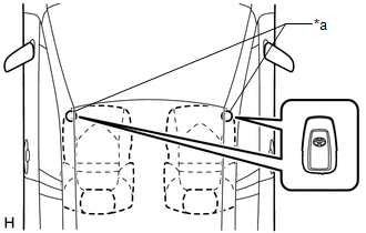
|
*a | Inspection Point |
HINT:
Place the electrical key transmitter sub-assembly on the front seat cushion of the driver seat or front passenger seat.
(f) *4: No. 1 indoor electrical key antenna assembly (rear floor)
|
*a | Inspection Point |
HINT:
Place the electrical key transmitter sub-assembly on the rear seat cushion.
(g) *5, *7: Electrical key antenna (outside luggage compartment)
|
*a | 0.7 to 1 m (2.30 to 3.28 ft.) |
HINT:
Hold the electrical key transmitter sub-assembly at the same height as the rear bumper upper surface and align it with the center of the rear of the vehicle as shown in the illustration.
(h) *6: No. 1 indoor electrical key antenna assembly (inside luggage compartment)
|
*a | Inspection Point |
HINT:
Place the electrical key transmitter sub-assembly on the luggage room floor.
(i) *8: Amplifier (engine switch)
|
*1 | Engine Switch |
|
*2 | Electrical Key Transmitter Sub-assembly |
HINT:
While facing the logo side of the electrical key transmitter sub-assembly toward the engine switch, hold the transmitter near the engine switch.
PARTS LOCATION
ILLUSTRATION
|
*1 | LUGGAGE DOOR COURTESY LIGHT SWITCH |
*2 | FRONT DOOR COURTESY LIGHT SWITCH ASSEMBLY (for LH) |
|
*3 | FRONT DOOR COURTESY LIGHT SWITCH ASSEMBLY (for RH) |
*4 | FRONT DOOR LOCK WITH MOTOR ASSEMBLY LH |
|
*5 | FRONT DOOR LOCK WITH MOTOR ASSEMBLY RH |
*6 | LUGGAGE COMPARTMENT DOOR LOCK ASSEMBLY |
|
*7 | REAR DOOR COURTESY LIGHT SWITCH ASSEMBLY (for LH) |
*8 | REAR DOOR COURTESY LIGHT SWITCH ASSEMBLY (for RH) |
|
*9 | REAR DOOR LOCK WITH MOTOR ASSEMBLY LH |
*10 | REAR DOOR LOCK WITH MOTOR ASSEMBLY RH |
ILLUSTRATION
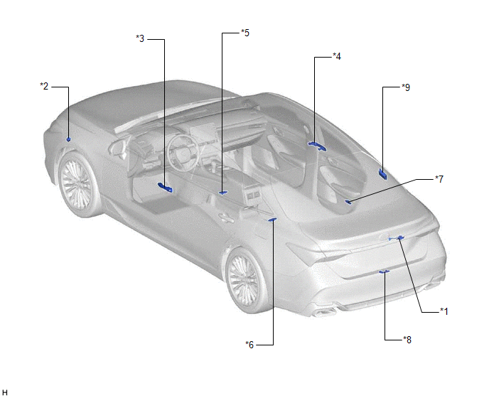
|
*1 | LUGGAGE ELECTRICAL KEY SWITCH |
*2 | WIRELESS DOOR LOCK BUZZER |
|
*3 | FRONT DOOR OUTSIDE HANDLE ASSEMBLY (for Driver Door) - ELECTRICAL KEY ANTENNA - LOCK SENSOR - UNLOCK SENSOR |
*4 | FRONT DOOR OUTSIDE HANDLE ASSEMBLY (for Front Passenger Door) - ELECTRICAL KEY ANTENNA - LOCK SENSOR - UNLOCK SENSOR |
|
*5 | NO. 1 INDOOR ELECTRICAL KEY ANTENNA ASSEMBLY (FRONT FLOOR) |
*6 | NO. 1 INDOOR ELECTRICAL KEY ANTENNA ASSEMBLY (REAR FLOOR) |
|
*7 | NO. 1 INDOOR ELECTRICAL KEY ANTENNA ASSEMBLY (INSIDE LUGGAGE COMPARTMENT) |
*8 | ELECTRICAL KEY ANTENNA (OUTSIDE LUGGAGE COMPARTMENT) |
|
*9 | ELECTRICAL KEY AND TIRE PRESSURE MONITORING SYSTEM RECEIVER ASSEMBLY |
- | - |
ILLUSTRATION
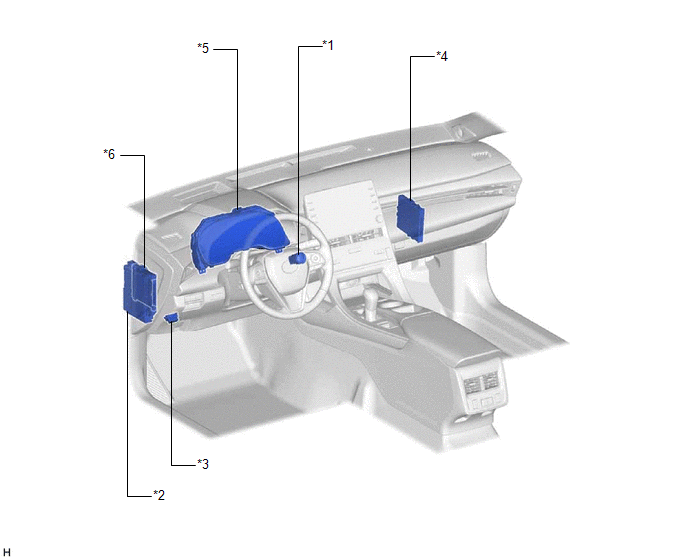
|
*1 | ENGINE SWITCH |
*2 | INSTRUMENT PANEL JUNCTION BLOCK ASSEMBLY - AM2 FUSE |
| *3 |
DLC3 | *4 |
CERTIFICATION ECU (SMART KEY ECU ASSEMBLY) |
|
*5 | COMBINATION METER ASSEMBLY |
*6 | MAIN BODY ECU (MULTIPLEX NETWORK BODY ECU) |
PRECAUTION
CAUTION REGARDING INTERFERENCE WITH ELECTRONIC DEVICES
CAUTION:
As weak radio waves are emitted from the electrical key transmitter sub-assembly, if a pacemaker is being used, be sure to read the pacemaker instruction manual and the following.
Click here 
| Exterior antenna |
|
| Interior antenna |
|
HINT:
Smart key system can be disabled by customize function.
Click here
PRECAUTION FOR DISCONNECTING CABLE FROM NEGATIVE BATTERY TERMINAL
NOTICE:
Click here
|
System Name | See Procedure |
|---|---|
|
Lane Departure Alert System (w/ Steering Control) |
|
|
Intelligent Clearance Sonar System | |
|
Parking Assist Monitor System | |
|
Panoramic View Monitor System | |
|
Pre-collision System | |
|
Lighting System (for Gasoline Model with Cornering Light) |
SMART KEY SYSTEM SPECIFICATIONS
(a) Some customers may inquire about the frequency used by the smart key system on various models. This repair manual contains the applicable specifications of the smart key system.
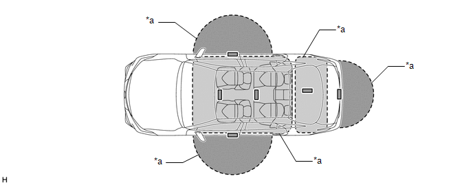
|
*a | Transmitter Detection Area |
- | - |
|
Specification | ||||
|---|---|---|---|---|
|
Frequency | Output Power/Electric Field Intensity |
Modulation Method | Mounting Point in Vehicle | |
|
Inside Passenger Compartment |
134.2 kHz | 94.4 dBuV/m at 3 m |
AM | Inside vehicle |
|
Inside Luggage Compartment |
134.2 kHz | 94.4 dBuV/m at 3 m |
AM | Inside luggage compartment |
|
Outside Vehicle |
134.2 kHz | 95 dBuV/m at 3 m |
AM | Inside door handle |
|
95 dBuV/m at 3 m | AM |
Inside rear bumper | ||
|
Transmission Timing | |||
|---|---|---|---|
|
Vehicle Remains Parked |
Entering or Exiting the Vehicle |
Vehicle is being Driven | |
| Inside Passenger Compartment |
Does not transmit |
| When electrical key transmitter sub-assembly is not detected inside cabin while vehicle is being driven (transmits for 4 seconds) |
|
Inside Luggage Compartment |
Does not transmit |
| Does not transmit |
|
Outside Vehicle | When door is locked, transmits at 250 ms intervals (stops when door is unlocked) |
| Does not transmit |
PRECAUTION WHEN USING TECHSTREAM
(a) When using the Techstream with the engine switch off, connect the Techstream to the DLC3 and turn a courtesy light switch on and off at intervals of 1.5 seconds or less until communication between the Techstream and the vehicle begins. Then select the vehicle type under manual mode and enter the following menus: Body Electrical / Smart Key. While using the Techstream, periodically turn a courtesy light switch on and off at intervals of 1.5 seconds or less to maintain communication between the Techstream and the vehicle.
PRECAUTION RELATED TO VEHICLE BATTERY
(a) The entry unlock function may not operate immediately after the cables are reconnected to the battery. If this occurs, the entry unlock function can be restored by performing a wireless door lock and unlock or mechanical key operation.
(b) When the doors are locked, electrical waves are sent from the vehicle, which uses power from the battery. This means that the battery may be depleted if the vehicle is left for a long time. When not using the vehicle for a long time, disconnect the cable from the negative (-) battery terminal or cancel the smart key system.
HINT:
Smart key system can be disabled by customize function.
Click here
PRECAUTION WHEN REPLACING PARTS
(a) If replacing any of the following parts, refer to the Registration.
Click here
(1) Certification ECU (smart key ECU assembly)
(2) Main body ECU (multiplex network body ECU)
(3) Electrical key transmitter sub-assembly
(b) If the electrical key and tire pressure monitoring system receiver assembly is replaced, it is necessary to register the electrical key transmitter sub-assemblies to the new electrical key and tire pressure monitoring system receiver assembly and perform registration and initialization.
HINT:
Click here
Click here
PRECAUTIONS FOR ELECTRICAL KEY TRANSMITTER SUB-ASSEMBLY
(a) The electrical key transmitter sub-assembly is a precision instrument. Be sure to observe the following:
(1) Do not subject the electrical key transmitter sub-assembly to strong physical shocks.
(2) Do not keep the electrical key transmitter sub-assembly in a high temperature area for a long time.
(3) Do not use an ultrasonic washing machine to clean the electrical key transmitter sub-assembly.
(4) Do not use the electrical key transmitter sub-assembly near any magnets or magnetized items.
(5) Do not place the electrical key transmitter sub-assembly near magnetic equipment, such as digital audio players, induction cookers, medical devices that generate low-frequency electromagnetic waves, etc.
(6) Do not attach any stickers to the electrical key transmitter sub-assembly.
(7) Do not disassemble the electrical key transmitter sub-assemblies.
(8) The mechanical key should only be used in an emergency, such as when the transmitter battery is depleted.
(b) When the doors are locked and an electrical key transmitter sub-assembly is in the detection area of an electrical key antenna, the transmitter battery may be depleted due to periodic communication between the electrical key transmitter sub-assembly and the vehicle. If the vehicle is not to be used for a long time, keep the key away from the vehicle (more than 2 m (6.56 ft.)).
HINT:
To set the transmitter battery saving mode function, refer to the smart key system (for Start Function, Gasoline Model).
Click here
PRECAUTIONS WHEN INSPECTING SMART KEY SYSTEM (for Entry Function, Gasoline Model)
(a) General precaution for the smart key system (for Entry Function, Gasoline Model):
(1) Always carry the electrical key transmitter sub-assembly.
(b) The smart key system (for Entry Function, Gasoline Model) may not operate normally or the key detection area may decrease in the following situations:
(1) The transmitter battery is depleted.
(2) There are TV towers, electric power plants, broadcasting stations, gas stations or other facilities that generate strong radio waves or electrical noise nearby.
(3) Wireless communication devices, such as walkie-talkies, cell phones, cordless telephones, digital audio players, portable game systems, etc., are carried together with the electrical key transmitter sub-assembly.
(4) The electrical key transmitter sub-assembly is covered by or in contact with objects made of metal, such as coins, certain types of cards, etc.
(5) Metallic film is applied to the rear window glass.
(6) A radio wave type keyless entry system or wireless remote is operated nearby.
(7) An electrical key transmitter sub-assembly from another vehicle is nearby.
(8) The electrical key transmitter sub-assembly is placed near equipment that generates high-voltage or electrical noise.
(9) The electrical key transmitter sub-assembly is placed near an electronic device such as a battery charger.
(c) Operating range of the smart key system (for Entry Function, Gasoline Model):
(1) Due to the design of the vehicle body, there are some areas in which proper system operation is difficult.
(2) Even if the electrical key transmitter sub-assembly is in the vehicle exterior detection area, the electrical key transmitter sub-assembly may not be properly detected if the electrical key transmitter sub-assembly is near a window, a door handle or the center of the bumper.
(3) Even if an electrical key transmitter sub-assembly is in a vehicle interior detection area, the electrical key transmitter sub-assembly may not be properly detected if it is on the instrument panel, in the glove box or on the floor.
(4) Depending on the way the electrical key transmitter sub-assembly is held, the electrical key transmitter sub-assembly may not operate properly.
(d) As weak radio waves are emitted from the electrical key transmitter sub-assembly, if a pacemaker is being used, be sure to read the pacemaker instruction manual.
(e) The smart key system (for Entry Function, Gasoline Model) will not operate under the following conditions:
(1) The procedure to cancel the smart key system (for Entry Function, Gasoline Model) has been performed.
(2) There is no transmitter battery or the transmitter battery is depleted (the LED of the electrical key transmitter sub-assembly does not blink when an electrical key transmitter sub-assembly switch is pressed).
PRECAUTIONS FOR ENTRY UNLOCK FUNCTION
(a) When unlocking the doors, make sure to grasp the door outside handle assembly, ensuring contact with the sensor on the inner part of the handle. Pull the handle after confirming that the door has unlocked.
(b) If the door outside handle assembly is grasped with gloved hands, unlocking may be delayed or may not occur.
(c) When performing an entry unlock operation, make sure to check that the doors are unlocked before pulling a door outside handle assembly to open a door.
(d) When attempting to open a door suddenly or immediately after entering a vehicle exterior detection area, the door may not unlock. In this case the system automatically performs the door unlock operation 4 times. However, if a door outside handle assembly is being pulled at this time, the door may not unlock due to mechanical reasons. If the door is not unlocked, return the door outside handle to its original position and pull the handle after confirming that the door has unlocked.
(e) If the electrical key transmitter sub-assembly is brought too close to the door outside handle assembly, it may not be possible to unlock the door with the entry unlock function.
(f) If an electrical key transmitter sub-assembly is within a vehicle exterior detection area, the door can be unlocked even when a person other than the person carrying the electrical key transmitter sub-assembly grasps the door outside handle assembly. However, doors other than the door for which the matching code is detected cannot be unlocked (if the electrical key transmitter sub-assembly is in the vehicle exterior detection area of the driver side door and the front door outside handle assembly (for driver door) is held, the doors can be unlocked. However, if the front door outside handle assembly (for front passenger door) is held, the doors cannot be unlocked).
(g) After a wireless door lock, manual door lock or key-linked door lock operation is performed with the electrical key transmitter sub-assembly in an interior detection area or near the vehicle, an entry unlock operation cannot be performed. Therefore, when a wireless door lock operation is performed near a window or door handle, the entry unlock may not be able to be operated. To unlock the doors, perform a wireless door unlock operation.
(h) If a door is not opened after a door unlock operation, the doors automatically lock after approximately 60 seconds*.
(i) If an electrical key transmitter sub-assembly is within a vehicle exterior detection area and a large amount of water is applied to a door outside handle assembly, such as by a car wash or heavy rain, the sensor may react and the entry unlock operation may be performed. However, the doors will automatically lock after approximately 60 seconds if a door is not opened*.
(j) If the electrical key transmitter sub-assembly is being carried together with an electrical key transmitter sub-assembly from another vehicle with a smart key system and the door outside handle assembly is held, the time before the door is unlocked by the entry unlock operation may be more than normal.
HINT:
*: When the auto lock function operates after an entry unlock operation, if an electrical key transmitter sub-assembly is detected in the cabin, the doors will be unlocked by the door ajar warning function.
PRECAUTIONS FOR ENTRY LOCK FUNCTION
(a) When performing an entry lock operation, if the lock sensor on the door outside handle assembly is touched too quickly, the door may not lock.
(b) If the electrical key transmitter sub-assembly is brought near the vehicle interior (window, door outside handle assembly), the entry lock function may not operate. Also, the key reminder warning buzzer may sound and the entry unlock function may stop operating. In this case, move the electrical key transmitter sub-assembly away from the vehicle interior (window, door outside handle assembly), perform an entry lock operation, and then perform an entry unlock operation.
(c) If the electrical key transmitter sub-assembly is being carried and a lock operation is performed from the driver door while the driver door is open (the door is ajar), the door ajar warning does not operate.
(d) If the electrical key transmitter sub-assembly is left on the instrument panel, in the glove box or on the floor, the key reminder warning function may not operate and the electrical key transmitter sub-assembly may be locked in the vehicle when a door lock operation is performed. Always carry the electrical key transmitter sub-assembly.
(e) The entry unlock operation cannot be performed for approximately 3 seconds after an operation that locks the doors, such as an entry lock or wireless door lock operation, is performed.
(f) When checking the operation of the entry lock function several times, it can only be operated up to 2 times consecutively depending on the setting. To perform the operation 3 times or more consecutively, the doors need to be unlocked once (any unlock operation is acceptable). However, this is only for the entry lock function, other door lock functions, such as the wireless door lock function, can be operated consecutively.
PROBLEM SYMPTOMS TABLE
HINT:
|
Symptom | Suspected Area |
Link |
|---|---|---|
|
Key vehicle inside lock-in prevention function does not operate |
External electrical waves |
|
|
Harness or connector | ||
|
No. 1 indoor electrical key antenna assembly (front floor) | ||
|
No. 1 indoor electrical key antenna assembly (rear floor) | ||
|
Certification ECU (Smart key ECU assembly) | ||
|
Transmitter battery | ||
|
instrument panel junction block assembly | ||
|
Engine switch | ||
|
All door entry lock/unlock functions and wireless functions do not operate |
Lighting system |
|
|
Power door lock control system | ||
|
External electrical waves | ||
|
Code registration | ||
|
Transmitter battery | ||
|
Harness or connector | ||
|
Electrical key transmitter sub-assembly | ||
|
Electrical key and tire pressure monitoring system receiver assembly | ||
|
Main body ECU (Multiplex network body ECU) | ||
|
Certification ECU (Smart key ECU assembly) | ||
|
All door entry lock/unlock functions do not operate, but wireless functions operate |
Check customize setting (Entry cancel function (manual operation)) |
|
|
External electrical waves | ||
|
Electrical key transmitter sub-assembly | ||
|
Certification ECU (Smart key ECU assembly) | ||
|
Driver side door entry unlock function does not operate |
Power door lock control system |
|
|
Harness or connector | ||
|
Front door outside handle assembly (for driver door) | ||
|
Lighting system | ||
|
Certification ECU (Smart key ECU assembly) | ||
|
Front passenger side door entry unlock function does not operate |
Power door lock control system |
|
|
Harness or connector | ||
|
Front door outside handle assembly (for front passenger door) | ||
|
Lighting system | ||
|
Certification ECU (Smart key ECU assembly) | ||
|
Driver side door entry lock and unlock functions do not operate |
Power door lock control system |
|
|
External electrical waves | ||
|
Harness or connector | ||
|
Front door outside handle assembly (for driver door) | ||
|
Certification ECU (Smart key ECU assembly) | ||
|
Front passenger side door entry lock and unlock functions do not operate |
Power door lock control system |
|
|
External electrical waves | ||
|
Harness or connector | ||
|
Front door outside handle assembly (for front passenger door) | ||
|
Certification ECU (Smart key ECU assembly) | ||
|
Driver side door entry lock function does not operate |
Power door lock control system |
|
|
Harness or connector | ||
|
Front door outside handle assembly (for driver door) | ||
|
Certification ECU (Smart key ECU assembly) | ||
|
Front passenger side door entry lock function does not operate |
Power door lock control system |
|
|
Harness or connector | ||
|
Front door outside handle assembly (for front passenger door) | ||
|
Certification ECU (Smart key ECU assembly) | ||
|
Luggage compartment door entry unlock function does not operate when key is outside luggage compartment |
Check customize setting (Trunk Open Mode) |
|
|
External electrical waves | ||
|
Luggage compartment door opener system | ||
|
Harness or connector | ||
|
Luggage electrical key switch | ||
|
No. 1 indoor electrical key antenna assembly (inside luggage compartment) | ||
|
Certification ECU (Smart key ECU assembly) | ||
|
Key luggage compartment lock-in prevention function does not operate |
External electrical waves |
|
|
Harness or connector | ||
|
No. 1 indoor electrical key antenna assembly (inside luggage compartment) | ||
|
Certification ECU (Smart key ECU assembly) | ||
|
Entry interior alarm does not sound |
METER/GAUGE System |
|
|
Entry exterior alarm and answer-back buzzer do not sound |
Check customize setting (Wireless Buzzer Resp) |
|
|
Lighting system | ||
|
Harness or connector | ||
|
instrument panel junction block assembly | ||
|
Wireless door lock buzzer | ||
|
Main body ECU (Multiplex network body ECU) | ||
|
Certification ECU (Smart key ECU assembly) | ||
|
Touching unlock sensor for certain period of time does not unlock all doors |
Check customize setting (Door Unlock Mode 2 and Door Unlock Sensor Touch Time Adjust) |
|
|
Power door lock control system | ||
|
Certification ECU (Smart Key ECU Assembly) | ||
|
When returning to the vehicle, although door unlock operation was not performed, doors were in an unlocked state |
Power door lock control system |
|
|
When returning to the vehicle, although door lock operation was not performed, doors were in a locked state |
Power door lock control system |
|
SYSTEM DIAGRAM
SMART KEY SYSTEM (for Entry Function, Gasoline Model)
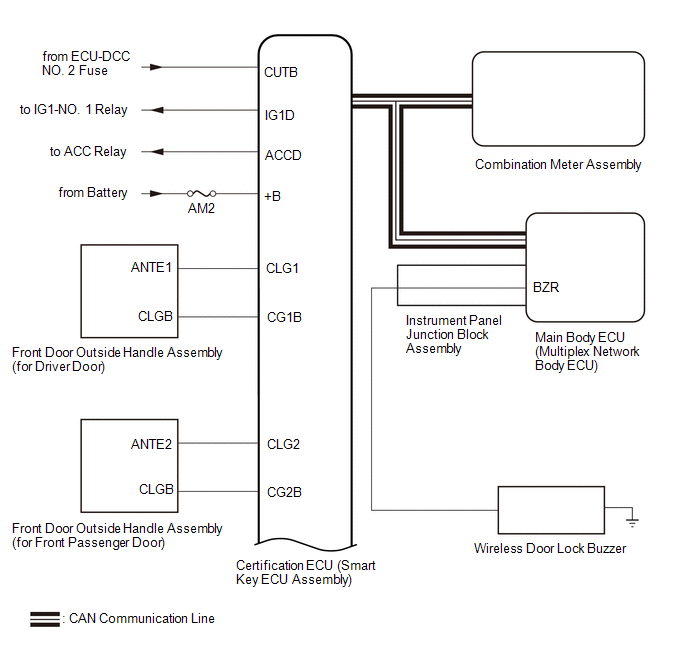
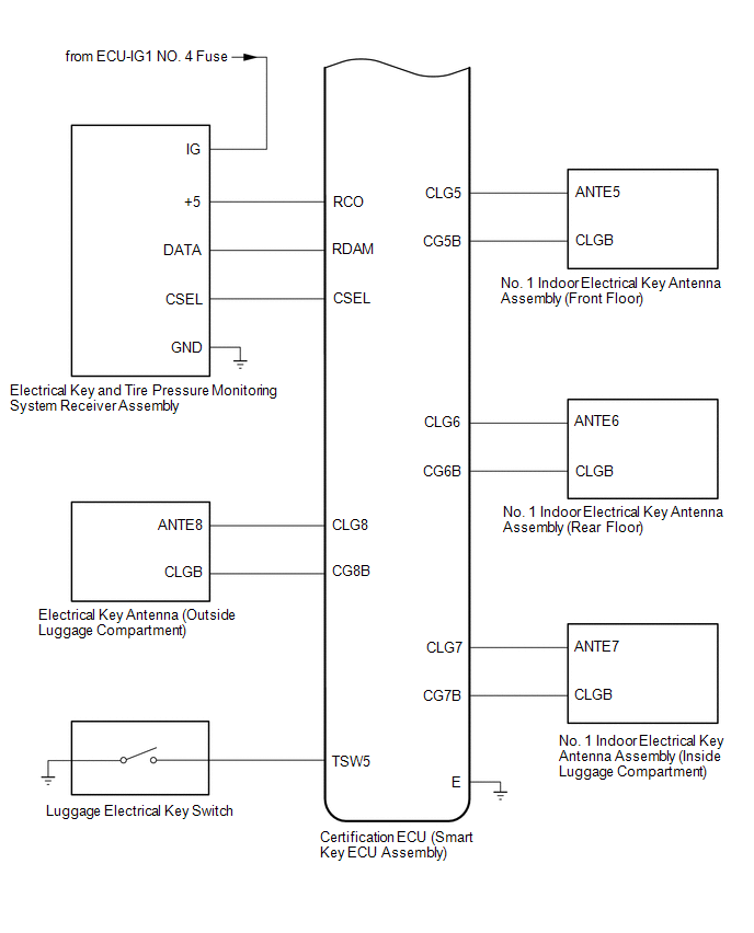
SMART KEY SYSTEM (for Start Function, Gasoline Model)
Click here 
POWER DOOR LOCK CONTROL SYSTEM (for Gasoline Model)
Click here
WIRELESS DOOR LOCK CONTROL SYSTEM (for Gasoline Model)
Click here
LUGGAGE COMPARTMENT DOOR OPENER SYSTEM (for Gasoline Model)
Click here
TERMINALS OF ECU
CHECK CERTIFICATION ECU (SMART KEY ECU ASSEMBLY)
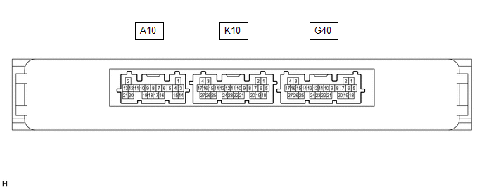
(a) Disconnect the G40 certification ECU (smart key ECU assembly) connector.
(b) Measure the voltage and resistance according to the value(s) in the table below.
|
Tester Connection | Wiring Color |
Input/Output | Terminal Description |
Condition | Specified Condition |
|---|---|---|---|---|---|
|
G40-18 (E) - Body ground |
W-B - Body ground | - |
Ground | Always |
Below 1 Ω |
|
G40-4 (+B) - G40-18 (E) |
W - W-B | Input |
Power supply | Always |
11 to 14 V |
|
G40-15 (CUTB) - G40-18 (E) |
R - W-B | Input |
Dark current cut pin* |
Always | 11 to 14 V |
(c) Reconnect the G40 certification ECU (smart key ECU assembly) connector.
(d) Measure the voltage and check for pulses according to the value(s) in the table below.
|
Tester Connection | Wiring Color |
Input/Output | Terminal Description |
Condition | Specified Condition |
|---|---|---|---|---|---|
|
G40-17 (IG1D) - G40-18 (E) |
R - W-B | Output |
IG power supply | Engine switch off → on (IG) |
Below 1 V → 10 V or higher |
|
K10-17 (CLG1) - G40-18 (E) |
R - W-B | Output |
Output to driver door electrical key antenna (request signal (challenge) is sent to door electrical key antenna from certification ECU (smart key ECU assembly) to form detection area) |
Procedure:
| Pulse generation (See waveform 1) |
| Procedure:
| Pulse generation (See waveform 2) | ||||
|
K10-17 (CLG1) - G40-18 (E) |
R - W-B | Input |
Input to driver door lock sensor (front door outside handle assembly (for driver door) lock sensor on signal is sent to the certification ECU (smart key ECU assembly)) |
Procedure:
| Pulse generation (See waveform 3) |
|
K10-17 (CLG1) - G40-18 (E) |
R - W-B | Input |
Input to driver door unlock sensor (when system is in unlock standby mode and unlock sensor is touched, door electrical key antenna sends unlock sensor input signal (sensing) to certification ECU (smart key ECU assembly)) | Procedure:
| Pulse generation (See waveform 4) |
|
K10-16 (CG1B) - G40-18 (E) |
GR - W-B |
Output | Output to driver door electrical key antenna (terminal on opposite side of component from CLG1 output terminal) |
Procedure:
| Pulse generation (See waveform 5) |
| Procedure:
| Pulse generation (See waveform 6) | ||||
|
K10-15 (CLG2) - G40-18 (E) |
R - W-B | Output |
Output to front passenger door electrical key antenna (request signal (challenge) is sent to door electrical key antenna from certification ECU (smart key ECU assembly) to form detection area) |
Procedure:
| Pulse generation (See waveform 1) |
| Procedure:
| Pulse generation (See waveform 2) | ||||
|
K10-15 (CLG2) - G40-18 (E) |
R - W-B | Input |
Input to front passenger door lock sensor (front door outside handle assembly (for front passenger door) lock sensor on signal is sent to the certification ECU (smart key ECU assembly)) |
Procedure:
| Pulse generation (See waveform 3) |
|
K10-15 (CLG2) - G40-18 (E) |
R - W-B | Input |
Input to front passenger door unlock sensor (when system is in unlock standby mode and unlock sensor is touched, door electrical key antenna sends unlock sensor input signal (sensing) to certification ECU (smart key ECU assembly)) | Procedure:
| Pulse generation (See waveform 4) |
|
K10-14 (CG2B) - G40-18 (E) |
W - W-B | Output |
Output to front passenger door electrical key antenna (terminal on opposite side of component from CLG2 output terminal) |
Procedure:
| Pulse generation (See waveform 5) |
| Procedure:
| Pulse generation (See waveform 6) | ||||
|
K10-11 (CLG7) - G40-18 (E) |
GR - W-B | Output |
Output to No. 1 indoor electrical key antenna assembly (inside luggage compartment) |
Procedure:
| Pulse generation (See waveform 7) |
|
K10-10 (CG7B) - G40-18 (E) |
R - W-B | Output |
Output to No. 1 indoor electrical key antenna assembly (inside luggage compartment) (terminal on opposite side of component from CLG7 output terminal) | Procedure:
| Pulse generation (See waveform 7) |
|
K10-13 (CLG8) - G40-18 (E) |
G - W-B | Output |
Output to electrical key antenna (outside luggage compartment) |
Procedure:
| Pulse generation (See waveform 8) |
|
K10-12 (CG8B) - G40-18 (E) |
L - W-B | Output |
Output to electrical key antenna (outside luggage compartment) (terminal on opposite side of component from CLG8 output terminal) |
Procedure:
| Pulse generation (See waveform 8) |
|
K10-26 (TSW5) - G40-18 (E) |
LG - W-B | Input |
Luggage electrical key switch signal input |
Luggage electrical key switch off → on |
Pulse generation (See waveform 9) |
|
K10-18 (RCO) - G40-18 (E) |
B - W-B | Output |
Output to electrical key and tire pressure monitoring system receiver assembly (Power supply for electrical key and tire pressure monitoring system receiver assembly. Certification ECU (smart key ECU assembly) outputs 5 V when receiver starts operating.) | Procedure:
| Pulse generation (See waveform 10) |
|
K10-19 (RDAM) - G40-18 (E) |
G - W-B | Input |
Electrical key and tire pressure monitoring system receiver assembly verifies data received from electrical key transmitter sub-assembly. Electrical key and tire pressure monitoring system receiver assembly sends data from electrical key transmitter sub-assembly to certification ECU (smart key ECU assembly) (Electrical key and tire pressure monitoring system receiver assembly intermittently grounds 12 V signal from certification ECU (smart key ECU assembly)). | Proceed:
| Pulse generation (See waveform 11) |
|
K10-20 (CSEL) - G40-18 (E) |
BE - W-B | Output |
Communication channel switching circuit |
Procedure:
| Below 1 V → Pulse generation |
Click here 
(e) Using an oscilloscope, check waveform 1.
NOTICE:
The oscilloscope waveform shown in the illustration is an example for reference only. Noise, chattering, etc. are not shown.
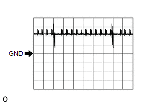 Waveform 1 (Reference)
 |
Item | Content |
|---|---|
|
Tester Connection | K10-17 (CLG1) - G40-18 (E) K10-15 (CLG2) - G40-18 (E) |
|
Tool Setting | 5 V/DIV., 500 ms/DIV. |
|
Condition | Procedure:
|
Click here
(f) Using an oscilloscope, check waveform 2.
NOTICE:
The oscilloscope waveform shown in the illustration is an example for reference only. Noise, chattering, etc. are not shown.
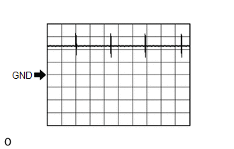 Waveform 2 (Reference)
 |
Item | Content |
|---|---|
|
Tester Connection | K10-17 (CLG1) - G40-18 (E) K10-15 (CLG2) - G40-18 (E) |
|
Tool Setting | 5 V/DIV., 100 ms/DIV. |
|
Condition | Procedure:
|
Click here
(g) Using an oscilloscope, check waveform 3.
NOTICE:
The oscilloscope waveform shown in the illustration is an example for reference only. Noise, chattering, etc. are not shown.
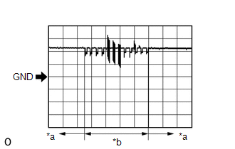
|
*a | Lock sensor not touched |
|
*b | Lock sensor touched |
|
Item | Content |
|---|---|
|
Tester Connection | K10-17 (CLG1) - G40-18 (E) K10-15 (CLG2) - G40-18 (E) |
|
Tool Setting | 5 V/DIV., 40 ms/DIV. |
|
Condition | Procedure:
|
Click here
(h) Using an oscilloscope, check waveform 4.
NOTICE:
The oscilloscope waveform shown in the illustration is an example for reference only. Noise, chattering, etc. are not shown.
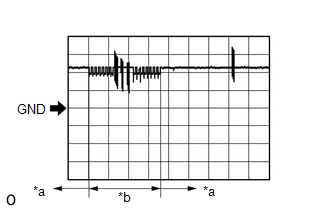
|
*a | Unlock sensor not touched |
|
*b | Unlock sensor touched |
|
Item | Content |
|---|---|
|
Tester Connection | K10-17 (CLG1) - G40-18 (E) K10-15 (CLG2) - G40-18 (E) |
|
Tool Setting | 5 V/DIV., 50 ms/DIV. |
|
Condition | Procedure:
|
(i) Using an oscilloscope, check waveform 5.
NOTICE:
The oscilloscope waveform shown in the illustration is an example for reference only. Noise, chattering, etc. are not shown.
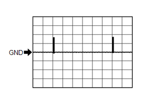 Waveform 5 (Reference)
 |
Item | Content |
|---|---|
|
Tester Connection | K10-16 (CG1B) - G40-18 (E) K10-14 (CG2B) - G40-18 (E) |
|
Tool Setting | 5 V/DIV., 500 ms/DIV. |
|
Condition | Procedure:
|
Click here
(j) Using an oscilloscope, check waveform 6.
NOTICE:
The oscilloscope waveform shown in the illustration is an example for reference only. Noise, chattering, etc. are not shown.
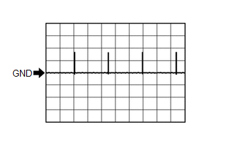 Waveform 6 (Reference)
 |
Item | Content |
|---|---|
|
Tester Connection | K10-16 (CG1B) - G40-18 (E) K10-14 (CG2B) - G40-18 (E) |
|
Tool Setting | 5 V/DIV., 100 ms/DIV. |
|
Condition | Procedure:
|
Click here
(k) Using an oscilloscope, check waveform 7.
NOTICE:
The oscilloscope waveform shown in the illustration is an example for reference only. Noise, chattering, etc. are not shown.
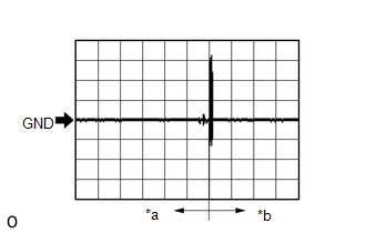
|
*a | Driver door lock sensor not touched |
|
*b | Driver door lock sensor touched |
|
Item | Content |
|---|---|
|
Tester Connection | K10-11 (CLG7) - G40-18 (E) K10-10 (CG7B) - G40-18 (E) |
|
Tool Setting | 2 V/DIV., 500 ms/DIV. |
|
Condition | Procedure:
|
(l) Using an oscilloscope, check waveform 8.
NOTICE:
The oscilloscope waveform shown in the illustration is an example for reference only. Noise, chattering, etc. are not shown.
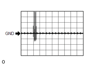 Waveform 8 (Reference)
 |
Item | Content |
|---|---|
|
Tester Connection | K10-13 (CLG8) - G40-18 (E) K10-12 (CG8B) - G40-18 (E) |
|
Tool Setting | 2 V/DIV., 500 ms/DIV. |
|
Condition | Procedure:
|
(m) Using an oscilloscope, check waveform 9.
NOTICE:
The oscilloscope waveform shown in the illustration is an example for reference only. Noise, chattering, etc. are not shown.
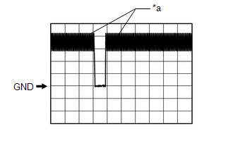
|
*a | Checking for switch on signal at short intervals |
|
Item | Content |
|---|---|
|
Tester Connection | K10-26 (TSW5) - G40-18 (E) |
|
Tool Setting | 2 V/DIV., 500 ms/DIV. |
|
Condition | Luggage electrical key switch off → on |
(n) Using an oscilloscope, check waveform 10.
NOTICE:
The oscilloscope waveform shown in the illustration is an example for reference only. Noise, chattering, etc. are not shown.
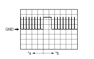
|
*a | Before lock or unlock switch of electrical key transmitter sub-assembly pressed |
|
*b | After lock or unlock switch of electrical key transmitter sub-assembly pressed |
|
Item | Content |
|---|---|
|
Tester Connection | K10-18 (RCO) - G40-18 (E) |
|
Tool Setting | 2 V/DIV., 500 ms/DIV. |
|
Condition | Procedure:
|
(o) Using an oscilloscope, check waveform 11.
NOTICE:
The oscilloscope waveform shown in the illustration is an example for reference only. Noise, chattering, etc. are not shown.
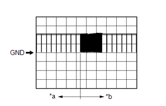
|
*a | Before lock or unlock switch of electrical key transmitter sub-assembly pressed |
|
*b | After lock or unlock switch of electrical key transmitter sub-assembly pressed |
|
Item | Content |
|---|---|
|
Tester Connection | K10-19 (RDAM) - G40-18 (E) |
|
Tool Setting | 5 V/DIV., 500 ms/DIV. |
|
Condition | Procedure:
|
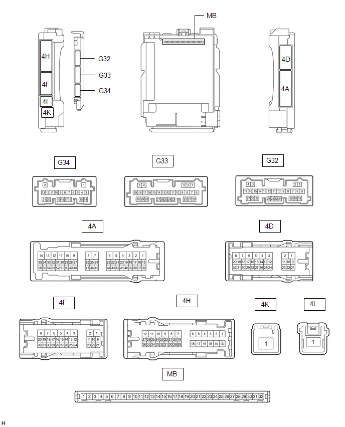
CHECK INSTRUMENT PANEL JUNCTION BLOCK ASSEMBLY AND MAIN BODY ECU (MULTIPLEX NETWORK BODY ECU)
(a) Remove the main body ECU (multiplex network body ECU) from the instrument panel junction block assembly.
Click here
(b) Measure the voltage and resistance according to the value(s) in the table below.
|
Tester Connection | Wiring Color |
Input/Output | Terminal Description |
Condition | Specified Condition |
|---|---|---|---|---|---|
|
MB-11 (GND1) - Body ground |
- | - |
Ground | Always |
Below 1 Ω |
|
MB-31 (BECU) - Body ground |
- | Input |
Battery power supply (for CPU) |
Always | 11 to 14 V |
DESCRIPTION
If the entry unlock function of the driver door cannot be operated by touching and holding the unlock sensor of the driver door, but can be operated through other methods, it can be determined that the request code is being transmitted properly from the driver door. In this case, the certification ECU (smart key ECU assembly) may be malfunctioning.
CAUTION / NOTICE / HINT
NOTICE:
Click here
HINT:
Touching the unlock sensor for a certain period of time to unlock all of the doors can only be performed if the customize setting "Door Unlock Mode2" is set to "Driver".
PROCEDURE
| 1. |
CHECK CUSTOMIZE SETTING (DOOR UNLOCK SENSOR TOUCH TIME ADJUST) |
(a) Connect the Techstream to the DLC3.
(b) Turn the engine switch on (IG).
(c) Turn the Techstream on.
(d) Enter the following menus: Customize Setting / Smart Key / Access.
Smart Key / Access|
Tester Display | Description |
Default | Setting |
ECU |
|---|---|---|---|---|
| Door Unlock Sensor Touch Time Adjust |
Function that sets the length of time the unlock sensor on the door outside handle assembly (for driver door) must be touched to unlock all of the doors | Middle |
00:OFF,01:Short,10:Middle,11:Long |
Certification ECU (Smart Key ECU Assembly) |
|
Result | Proceed to |
|---|---|
|
The customize setting is set to Short, Middle or Long |
A |
| The customize setting is set to OFF |
B |
| B |
| PERFORM CUSTOMIZE SETTING |
|
| 2. |
CHECK ENTRY UNLOCK FUNCTION (OPERATION CHECK) |
(a) Turn the engine switch off.
(b) Open and close the driver door.
(c) With the electrical key transmitter sub-assembly outside of the vehicle, press the lock switch of the electrical key transmitter sub-assembly to lock all of the doors.
(d) Hold the electrical key transmitter sub-assembly at the same height as the door outside handle assembly and approximately 0.3 m (0.984 ft.) from the driver door.
(e) Check that the LED of the electrical key transmitter sub-assembly blinks.
| (f) Touch and hold the unlock sensor on the door outside handle assembly (for driver door) for 2.5 seconds or more. HINT: When checking the operation of the unlock sensor again, make sure to perform the procedure from step (a). |
|
(g) Check that all of the doors unlock.
|
Result | Proceed to |
|---|---|
|
All of the doors do not unlock |
A |
| Any door does not unlock |
B |
| B |
| GO TO POWER DOOR LOCK CONTROL SYSTEM |
|
| 3. |
CHECK POWER DOOR LOCK CONTROL SYSTEM |
(a) When the door control switch on the multiplex network master switch assembly is operated, check that the doors unlock and lock according to the switch operation.
Click here
|
Result | Proceed to |
|---|---|
|
The door locks operate normally |
A |
| The door locks do not operate normally |
B |
| A |
| REPLACE CERTIFICATION ECU (SMART KEY ECU ASSEMBLY) |
| B |
| GO TO POWER DOOR LOCK CONTROL SYSTEM |
Toyota Avalon (XX50) 2019-2022 Service & Repair Manual > Can Communication System(for Gasoline Model): Check Bus 4 Lines for Short Circuit
DESCRIPTION There may be a short circuit between the CAN main bus lines and/or CAN branch lines when the resistance between terminals 22 (CA2H) and 7 (CA2L) of the central gateway ECU (network gateway ECU) is below 54 Ω. Symptom Trouble Area Resistance between terminals 22 (CA2H) and 7 (CA2L) of th ...