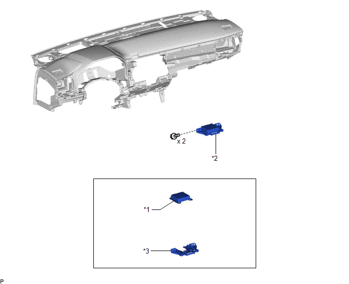
COMPONENTS
ILLUSTRATION
|
*1 | TELEPHONE AND GPS ANTENNA ASSEMBLY |
*2 | TELEPHONE AND GPS ANTENNA ASSEMBLY WITH BRACKET |
|
*3 | TELEPHONE AND GPS ANTENNA BRACKET |
- | - |
INSTALLATION
PROCEDURE
1. INSTALL TELEPHONE AND GPS ANTENNA BRACKET
2. INSTALL TELEPHONE AND GPS ANTENNA ASSEMBLY
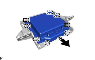
(a) Engage the 6 guides and 2 claws to install the telephone and GPS antenna assembly as shown in the illustration.
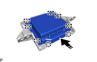
 |
Install in this Direction |
3. INSTALL TELEPHONE AND GPS ANTENNA ASSEMBLY WITH BRACKET
(a) Install the telephone and GPS antenna assembly with bracket with the 2 screws.
(b) Engage the 2 claws.
(c) Connect the connector.
4. INSTALL INSTRUMENT PANEL SAFETY PAD SUB-ASSEMBLY
Click here 
REMOVAL
CAUTION / NOTICE / HINT
The necessary procedures (adjustment, calibration, initialization, or registration) that must be performed after parts are removed and installed, or replaced during telephone and GPS antenna assembly removal/installation are shown below.
Necessary Procedure After Parts Removed/Installed/Replaced (for Gasoline Model)|
Replaced Part or Performed Procedure |
Necessary Procedure | Effect/Inoperative Function When Necessary Procedures are not Performed |
Link |
|---|---|---|---|
|
*: When performing learning using the Techstream.
Click here | |||
|
Disconnect cable from negative battery terminal |
Perform steering sensor zero point calibration |
Lane Departure Alert System (w/ Steering Control) |
|
|
Pre-collision System | |||
|
Intelligent Clearance Sonar System* | |||
|
Lighting System (for Gasoline Model with Cornering Light) | |||
|
Memorize steering angle neutral point |
Parking Assist Monitor System |
| |
|
Panoramic View Monitor System |
| ||
CAUTION:
Some of these service operations affect the SRS airbag system. Read the precautionary notices concerning the SRS airbag system before servicing.
Click here

 Necessary Procedure After Parts Removed/Installed/Replaced (for HV Model)
 |
Replaced Part or Performed Procedure |
Necessary Procedure | Effect/Inoperative Function When Necessary Procedures are not Performed |
Link |
|---|---|---|---|
|
*: When performing learning using the Techstream.
Click here | |||
|
Disconnect cable from negative auxiliary battery terminal |
Perform steering sensor zero point calibration |
Lane Departure Alert System (w/ Steering Control) |
|
|
Pre-collision System | |||
|
Intelligent Clearance Sonar System* | |||
|
Lighting System (for HV Model with Cornering Light) | |||
|
Memorize steering angle neutral point |
Parking Assist Monitor System |
| |
|
Panoramic View Monitor System |
| ||
CAUTION:
Some of these service operations affect the SRS airbag system. Read the precautionary notices concerning the SRS airbag system before servicing.
Click here
PROCEDURE
1. REMOVE INSTRUMENT PANEL SAFETY PAD SUB-ASSEMBLY
Click here
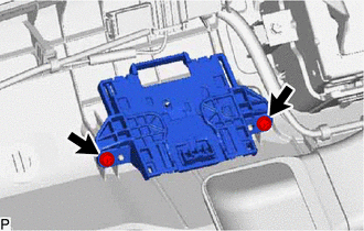
2. REMOVE TELEPHONE AND GPS ANTENNA ASSEMBLY WITH BRACKET
| (a) Disconnect the connector. |
|
(b) Disengage the 2 claws.
| (c) Remove the 2 screws and telephone and GPS antenna assembly with bracket. |
|
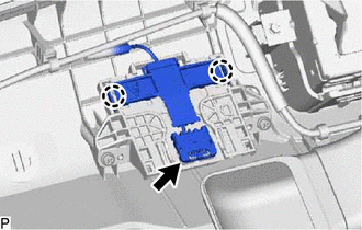
3. REMOVE TELEPHONE AND GPS ANTENNA ASSEMBLY
(a) Disengage the 2 claws and 6 guides to remove the telephone and GPS antenna assembly as shown in the illustration.
 |
Remove in this Direction |
4. REMOVE TELEPHONE AND GPS ANTENNA BRACKET
Toyota Avalon (XX50) 2019-2022 Service & Repair Manual > Power Outlets (int): Power Outlet Socket(for Console Box Front Side)
ComponentsCOMPONENTS ILLUSTRATION *1 USB CHARGER SOCKET - - InstallationINSTALLATION PROCEDURE 1. INSTALL USB CHARGER SOCKET (a) Engage the 4 claws to install the USB charger socket as shown in the illustration. Install in this Direction (b) Connect the connector. 2. INSTALL CONSOLE BOX ASSEMBLY Cl ...