|
Tester Display | Measurement Item |
Range | Normal Condition |
Diagnostic Note |
|
Unmatched Vehicle-ID | Key No. (incorrect or correct) |
No or Yes | No: Communication normal
Yes: Communication malfunction |
The
vehicle ID registered in the vehicle and the vehicle ID registered in
the electrical key transmitter sub-assembly are different (if a key from
another vehicle is brought into the vehicle exterior detection area
while the doors are locked, "Yes" is displayed for "Unmatched
Vehicle-ID" in the Data List). Other potential causes:
- An electrical key transmitter sub-assembly from a different vehicle is being used.
- A communication error due to wave interference.
- The electrical key transmitter sub-assembly or certification ECU (smart key ECU assembly) is malfunctioning.
|
| No Response |
Communication response |
No or Yes | No: Communication normal
Yes: Communication malfunction |
The
vehicle IDs registered in the vehicle and electrical key transmitter
sub-assembly match, but there is no response from the electrical key
transmitter sub-assembly. (If the electrical key transmitter
sub-assembly is not in the detection area or the transmitter battery is
depleted resulting in a matching code not being detected when a lock
switch or the engine switch is pressed, etc., "Yes" is displayed for "No
Response" in the Data List. If there is wave interference in the LF
band that the vehicle uses for transmission or the RF band that the
electrical key transmitter sub-assembly uses for transmission, "Yes" may
be displayed for "No Response" in the Data List.) Other potential causes:
- An electrical key transmitter sub-assembly from a different vehicle is being used.
- The electrical key transmitter sub-assembly or certification ECU (smart key ECU assembly) is malfunctioning.
|
| Key Low Battery |
Transmitter battery depleted |
No or Yes | No: Transmitter battery not depleted
Yes: Transmitter battery depleted |
The
electrical key transmitter sub-assembly sends voltage information to
the certification ECU (smart key ECU assembly) when it is transmitting.
"Yes" is displayed for the Data List item "Key Low Battery" when this
voltage information indicates 2.2 V or less. This Data List item should
be checked when the electrical key transmitter sub-assembly is at room
temperature (example: at -20°C (-4°F), "Yes" may be displayed even if
the transmitter battery is new). |
|
# Codes | Number of DTCs |
0 to 255 | - |
- |
| Immobilizer when IG=ON |
Immobiliser function status when engine switch on (IG) |
UNSET or SET | UNSET:
Immobiliser function not set with engine switch on (IG) or immobiliser
function unset 40 times after immobiliser function set SET: Immobiliser function set (driver door opened and closed with engine switch on (IG)) |
- |
| Immobiliser |
Immobiliser function status determined by certification ECU (smart key ECU assembly)*8 |
Set or Unset | Set: Immobiliser set (engine start prohibited) (engine switch off)
Unset: Immobiliser unset (engine start permitted) (engine switch on (ACC) or on (IG)) |
The engine cannot be started when Set is displayed.
HINT:
- The security indicator light blinks when Set is displayed.
- The security indicator light is linked with set/unset of the immobiliser and not linked with lock/unlock of the steering.
|
| Master Key |
Matching of master key ID code and ID code registered in certification ECU (smart key ECU assembly) |
NoMatch or Match | NoMatch: ID code of master key does not match ID code registered in certification ECU (smart key ECU assembly)
Match: ID code of master key matches ID code registered in certification ECU (smart key ECU assembly) |
- |
| Sub Key |
Matching of sub key ID code and ID code registered in certification ECU (smart key ECU assembly) |
NoMatch or Match | NoMatch: ID code of sub key does not match ID code registered in certification ECU (smart key ECU assembly)
Match: ID code of sub key matches ID code registered in certification ECU (smart key ECU assembly) |
- |
| BCC Malfunction |
BCC signal status of transponder chip*1 |
OK or NG | OK: BCC signal normal
NG:
BCC signal malfunction (malfunction in code computation in electrical
key transmitter sub-assembly/certification ECU (smart key ECU assembly)) |
Problems may be caused by the following:
- Communication errors due to wave interference (LF).
- The electrical key transmitter sub-assembly or certification ECU (smart key ECU assembly) malfunctioning.
|
| Abnormal Status |
Transponder chip status signal*1 |
OK or NG | OK: Transponder chip status signal normal
NG:
Transponder chip status signal malfunction (malfunction in code
computation in electrical key transmitter sub-assembly/certification ECU
(smart key ECU assembly)) | Problems may be caused by the following:
- Communication errors due to wave interference (LF).
- The electrical key transmitter sub-assembly or certification ECU (smart key ECU assembly) malfunctioning.
|
| Different Encrypt Code |
Matching of transponder chip code and certification ECU (smart key ECU assembly) code*1 |
OK or NG | OK: Codes of transponder chip and certification ECU (smart key ECU assembly) match
NG: Codes of transponder chip and certification ECU (smart key ECU assembly) do not match |
Problems may be caused by the following:
- An electrical key transmitter sub-assembly from a different vehicle is being used.
- The electrical key transmitter sub-assembly or certification ECU (smart key ECU assembly) malfunctioning.
|
| Different Serial Number |
Vehicle serial number*1 |
OK or NG | OK: Signal from transponder chip and vehicle serial number stored in the certification ECU (smart key ECU assembly) match
NG: Signal from transponder chip and vehicle serial number stored in the certification ECU (smart key ECU assembly) do not match |
Problems may be caused by the following:
- An electrical key transmitter sub-assembly from a different vehicle is being used.
- The electrical key transmitter sub-assembly or certification ECU (smart key ECU assembly) malfunctioning.
|
| Frame Error |
State of data sent from electrical key transmitter sub-assembly |
OK or NG | OK: No problem with data sent from electrical key transmitter sub-assembly
NG: Problem with data sent from electrical key transmitter sub-assembly |
Problems may be caused by the following:
- Communication errors due to wave interference.
- The electrical key transmitter sub-assembly or certification ECU (smart key ECU assembly) malfunctioning.
|
| Response |
Electrical key transmitter sub-assembly response to signal from certification ECU (smart key ECU assembly) |
OK or NG | OK: Electrical key transmitter sub-assembly responds to signal from certification ECU (smart key ECU assembly)
NG: Electrical key transmitter sub-assembly does not respond to signal from certification ECU (smart key ECU assembly) |
Problems may be caused by the following:
- A key from a different vehicle is being used.
- The electrical key transmitter sub-assembly, certification ECU (smart key ECU assembly) or engine switch malfunctioning.
|
| Wireless Starter Com ID |
Certification between remote engine start ECU and certification ECU (smart key ECU assembly) |
No Regd or Regd | No Regd: Certification between remote engine start ECU and certification ECU (smart key ECU assembly) not complete
Regd: Certification between remote engine start ECU and certification ECU (smart key ECU assembly) complete |
- |
| Wireless C Code |
Registration status between remote engine start ECU and certification ECU (smart key ECU assembly) |
No Regd or Regd | No Regd: Remote starter ID not registered to remote engine start ECU and certification ECU (smart key ECU assembly)
Regd: Remote starter ID registered to remote engine start ECU and certification ECU (smart key ECU assembly) |
Problems may be caused by the following:
- DTC B2779 is stored.
- Remote engine start ECU registration has not been performed.
- Malfunctions in the certification ECU (smart key ECU assembly) or remote engine start ECU.
|
| Steering Lock Sleep Cond |
Steering lock ECU sleep availability |
No or Yes | No: Sleep not available
Yes: Sleep available |
- |
| Steering Lock Start Cond |
Steering lock ECU wake up signal status |
No or Yes | No: Wake up signal not sent
Yes: Wake up signal sent |
- |
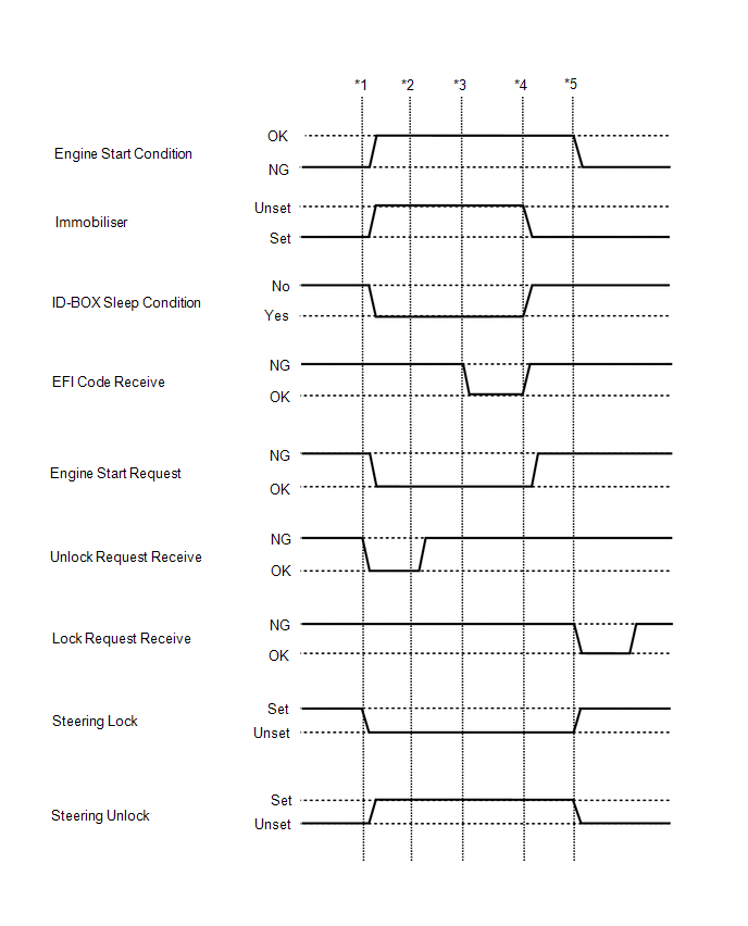
| Engine Start Condition |
Status
of engine start permission signal determined by steering lock ECU
(steering lock actuator or upper bracket assembly) and sent to
certification ECU (smart key ECU assembly)*2 |
NG or OK | NG: Engine start prohibited
OK: Engine start permitted |
- When OK is displayed, the certification ECU (smart key ECU assembly)
receives an unlock confirmation signal from the steering lock ECU
(steering lock actuator or upper bracket assembly) and makes fuel
injection and engine starting possible.
- The engine cannot be started when NG is displayed.
|
| Sensor Value |
History
of malfunction of position sensor in steering lock ECU (steering lock
actuator or upper bracket assembly) (DTC B2781 is stored) |
OK or NG(Past) | OK:
History of malfunction for the lock or unlock sensor in the steering
lock ECU (steering lock actuator or upper bracket assembly) does not
exist. NG(Past): History of both the lock and unlock
sensors in the steering lock ECU (steering lock actuator or upper
bracket assembly) being on exists. (Under normal operation, neither
sensor is on.) | When
NG(Past) is displayed, either the position sensor in the steering lock
ECU (steering lock actuator or upper bracket assembly) or the assembly
itself may be malfunctioning. |
|
Power Supply Short | History
of signal error (short) sent from certification ECU (smart key ECU
assembly) to steering lock ECU (steering lock actuator or upper bracket
assembly) (DTC B2782 is stored) |
OK or NG(Past) | OK: History of motor power source short does not exist
NG(Past): History of motor power source short exists |
This
item displays history of a malfunction in the circuit between the
certification ECU (smart key ECU assembly) and the steering lock ECU
(steering lock actuator or upper bracket assembly). |
|
Motor Driver Short | History
of malfunction (short) in steering lock ECU (steering lock actuator or
upper bracket assembly) motor circuit (DTC B2781 is stored) |
OK or NG(Past) | OK: History of short in the motor circuit does not exist
NG(Past): History of short in the motor circuit exists |
This
item displays history of a malfunction in the steering lock motor
circuit in the steering lock ECU (steering lock actuator or upper
bracket assembly). |
| Lock/Unlock Receive |
History of receiving an unlock request signal |
No or Yes | No: History of receiving an unlock request signal does not exist
Yes: History of receiving an unlock request signal exists |
- |
| Lock Bar Stuck Error |
History of steering not being able to unlock properly when steering lock operates for a certain period of time |
OK or NG(Past) | OK: History of steering lock being stuck does not exist
NG(Past): History of steering lock being stuck exists |
- |
| ID-BOX Sleep Condition |
Certification ECU (smart key ECU assembly) sleep mode status*8 |
No or Yes | No: Certification ECU (smart key ECU assembly) sleep mode not possible
Yes: Certification ECU (smart key ECU assembly) sleep mode possible |
- |
| ID-BOX Start Condition |
Certification ECU (smart key ECU assembly) status*3 |
No or Yes | No: Wake-up signal not sent by certification ECU (smart key ECU assembly)
Yes: Wake-up signal sent by certification ECU (smart key ECU assembly) |
- |
| Engine Start Request |
Status
of engine start permission signal determined by steering lock ECU
(steering lock actuator assembly) and sent to certification ECU (smart
key ECU assembly)*8 | OK or NG |
OK: Signal received NG: Signal not received |
- When OK is displayed, the certification ECU (smart key ECU assembly)
receives an unlock confirmation signal from the steering lock ECU
(steering lock actuator assembly) and makes fuel injection and engine
starting possible.
- The engine cannot be started when NG is displayed.
|
| 3bit Code Request |
3-bit code request condition |
OK or NG | OK: 3-bit code request condition signal received
NG: 3-bit code request condition signal not received |
- |
| L Code Check |
Verification result between certification ECU (smart key ECU assembly) and steering lock ECU (steering lock actuator assembly)*5 |
OK or NG | OK: Verification result normal
NG: Verification result abnormal |
When NG is displayed:
- The ID code for the certification ECU (smart key ECU assembly) or
steering lock ECU (steering lock actuator assembly) is not registered,
or the certification ECU (smart key ECU assembly) or steering lock ECU
(steering lock actuator assembly) is malfunctioning.
- The steering cannot be locked.
- The steering cannot be unlocked (the engine cannot be started).
|
| Unlock Request Receive |
Status of steering unlock command from certification ECU (smart key ECU assembly)*6,*8 |
OK or NG | OK:
Certification ECU (smart key ECU assembly) sends steering unlock
command (within 10 seconds of engine switch turned on (ACC) or on (IG),
or of engine start operation performed) NG:
Certification ECU (smart key ECU assembly) does not send steering unlock
command (engine switch not turned on (ACC) or on (IG), and engine start
operation not performed) |
- The engine cannot be started when an unlock request signal cannot be received.
- If OK is not displayed even though the steering unlock conditions are
met, the certification ECU (smart key ECU assembly) may be
malfunctioning.
|
| Lock Request Receive |
Status of steering lock command from certification ECU (smart key ECU assembly)*7,*8 |
OK or NG | OK:
Certification ECU (smart key ECU assembly) sends steering lock command
(within 10 seconds of any door opened with shift lever in P and engine
switch off) NG: Certification ECU (smart key ECU
assembly) does not send steering lock command (no door opened with shift
lever in P and engine switch off) |
If
OK is not displayed even though the steering lock conditions are met,
the certification ECU (smart key ECU assembly) may be malfunctioning. |
|
L Code Check(Past) | Verification
result history between the certification ECU (smart key ECU assembly)
and steering lock ECU (steering lock actuator assembly) |
OK or NG(Past) | OK: History of abnormal verification result does not exist
NG(Past): History of abnormal verification result exists |
- |
| Steering Lock |
Steering lock ECU (steering lock actuator or upper bracket assembly) lock confirmation status |
Unset or Set | Unset: Lock not confirmed
Set: Lock confirmed | When Unset is displayed, the steering is not locked. |
|
Steering Unlock | Steering lock ECU (steering lock actuator or upper bracket assembly) unlock confirmation status |
Unset or Set | Unset: Unlock not confirmed
Set: Unlock confirmed | When Unset is displayed, the steering is not unlocked (the engine cannot be started). |
|
EFI Code Receive | Certification
information sent to certification ECU (smart key ECU assembly) from ECM
when ECM receives engine start permission signal from certification ECU
(smart key ECU assembly)*4,*8 | OK or NG |
OK: Signal from ECM to unset immobiliser received by certification ECU (smart key ECU assembly)
NG: Signal from ECM to unset immobiliser not received by certification ECU (smart key ECU assembly) |
- |
| EFI Communication |
State of communication to unset immobiliser between certification ECU (smart key ECU assembly) and ECM |
OK or NG | OK: Communication to unset immobiliser has started between certification ECU (smart key ECU assembly) and ECM
NG: Communication to unset immobiliser has not started between certification ECU (smart key ECU assembly) and ECM |
If
this item displays "NG" even though the conditions to unset the
immobiliser have been met and the value of Data List item "Engine Start
Request" is "OK", the ECM may be malfunctioning. When the engine cannot
be started, use this Data List item during troubleshooting. |
|
B Code Difference | B code mismatch |
No or Yes | No: Communication normal
Yes: Communication malfunction |
- |
| B Code |
B code registration status |
No Regd or Regd | No Regd: B code not registered correctly
Regd: B code registered correctly |
- |
| Vehicle ID (Key Registration) |
Status of vehicle ID (key registration) |
OK or NG | OK: Vehicle ID registered to key
NG: Vehicle ID not registered to key |
- |
| Key Registration Status |
Status of key registration |
OK or NG | OK: Key registration was completed normally
NG: Key registration was not completed normally |
- |
| S/L Code Registration Status |
Status of L code registration |
OK or NG | OK: L code registration was completed normally
NG: L code registration was not completed normally |
- |
| Engine Start Indicator |
Key indicator display |
OFF or ON | Customize setting displayed |
- |
| Number of Registered Key Codes |
Number of registered electrical key transmitter sub-assemblies |
0 to 8 | Number of registered electrical key transmitter sub-assemblies |
Up to 7 electrical key transmitter sub-assemblies can be registered. |
|
Open in IG2 | History of IG2 input of the steering lock ECU (steering lock actuator or upper bracket assembly) |
OK or NG(Past) | OK: History of open in IG2 terminal circuit exists
NG(Past): No history of open in IG2 terminal circuit exists |
When
OK is displayed, the steering lock ECU (steering lock actuator or upper
bracket assembly) has an IG2 input circuit malfunction. |
|
EFI Communication Code Status |
Status of EFI communication code |
OK or NG | OK: Signal from ECM was correct
NG: Signal from ECM was incorrect |
- |
| EFI Communication Status |
Status of EFI communication |
OK or NG | OK: Communication normal between certification ECU (smart key ECU assembly) and ECM
NG: Communication malfunction between certification ECU (smart key ECU assembly) and ECM |
- |
| EFI Communication Speed |
Status of EFI communication speed |
OK or NG | OK: Communication speed normal
NG: Communication speed abnormal |
- |
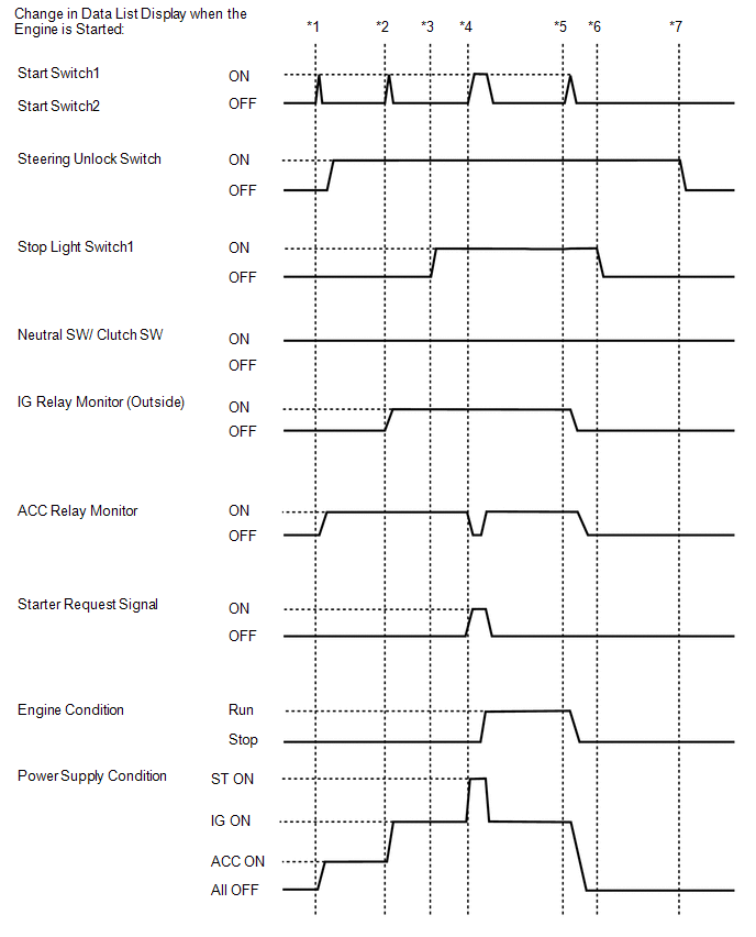 To check if the Data List display changes, get into the vehicle while
carrying an electrical key transmitter sub-assembly and perform the
following operations with the engine switch off and the shift lever in
P.
To check if the Data List display changes, get into the vehicle while
carrying an electrical key transmitter sub-assembly and perform the
following operations with the engine switch off and the shift lever in
P.