COMPONENTS
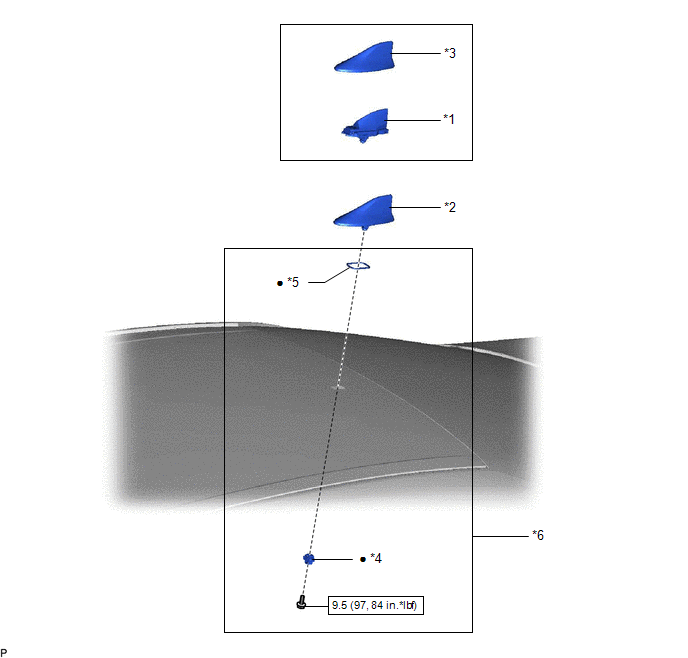
ILLUSTRATION
|
*1 | TELEPHONE AND GPS ANTENNA ASSEMBLY |
*2 | TELEPHONE AND GPS ANTENNA ASSEMBLY WITH COVER |
|
*3 | COVER |
*4 | WASHER AND HOLDER |
|
*5 | SEAL |
*6 | TELEPHONE ANTENNA HOUSING |
 |
N*m (kgf*cm, ft.*lbf): Specified torque |
● | Non-reusable part |
INSTALLATION
PROCEDURE
1. INSTALL TELEPHONE AND GPS ANTENNA ASSEMBLY
(a) When reusing the telephone and GPS antenna assembly:
(1) Install a new seal.
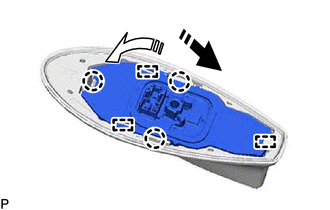
(b) Push the telephone and GPS antenna assembly in the direction indicated by the arrow (1) shown in the illustration to engage the guide.
 |
Install in this Direction (1) |
 |
Install in this Direction (2) |
(c) Push the telephone and GPS antenna assembly in the direction indicated by the arrow (2) shown in the illustration to engage the 2 guides and 3 claws and install the telephone and GPS antenna assembly.
2. INSTALL TELEPHONE AND GPS ANTENNA ASSEMBLY WITH COVER
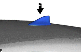
(a) Temporarily install the telephone and GPS antenna assembly with cover as shown in the illustration.
|
|
Install in this Direction |
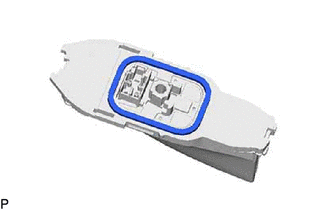
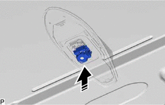
(b) Install a new washer and holder as shown in the illustration.
|
|
Install in this Direction |
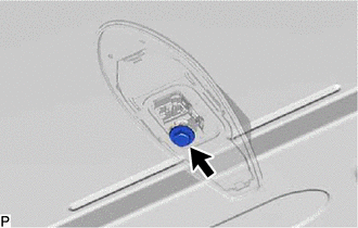
(c) Install the telephone and GPS antenna assembly with cover with the bolt.
Torque:
9.5 N·m {97 kgf·cm, 84 in·lbf}
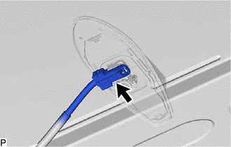
(d) Connect the connector.
3. INSTALL ROOF HEADLINING ASSEMBLY
Click here

REMOVAL
CAUTION / NOTICE / HINT
The necessary procedures (adjustment, calibration, initialization, or registration) that must be performed after parts are removed and installed, or replaced during telephone and GPS antenna assembly removal/installation are shown below.
Necessary Procedure After Parts Removed/Installed/Replaced (for Gasoline Model)|
Replaced Part or Performed Procedure |
Necessary Procedure | Effect/Inoperative Function When Necessary Procedures are not Performed |
Link |
|---|---|---|---|
|
*: When performing learning using the Techstream.
Click here | |||
|
Disconnect cable from negative battery terminal |
Perform steering sensor zero point calibration |
Lane Departure Alert System (w/ Steering Control) |
|
|
Pre-collision System | |||
|
Intelligent Clearance Sonar System* | |||
|
Lighting System (for Gasoline Model with Cornering Light) | |||
|
Memorize steering angle neutral point |
Parking Assist Monitor System |
| |
|
Panoramic View Monitor System |
| ||
|
Front passenger seat | Zero point calibration (Occupant classification system) |
|
|
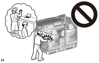
CAUTION:
Some of these service operations affect the SRS airbag system. Read the precautionary notices concerning the SRS airbag system before servicing.
Click here

 Necessary Procedure After Parts Removed/Installed/Replaced (for HV Model)
 |
Replaced Part or Performed Procedure |
Necessary Procedure | Effect/Inoperative Function When Necessary Procedures are not Performed |
Link |
|---|---|---|---|
|
*: When performing learning using the Techstream.
Click here | |||
|
Disconnect cable from negative auxiliary battery terminal |
Perform steering sensor zero point calibration |
Lane Departure Alert System (w/ Steering Control) |
|
|
Pre-collision System | |||
|
Intelligent Clearance Sonar System* | |||
|
Lighting System (for HV Model with Cornering Light) | |||
|
Memorize steering angle neutral point |
Parking Assist Monitor System |
| |
|
Panoramic View Monitor System |
| ||
|
Front passenger seat | Zero point calibration (Occupant classification system) |
|
|
CAUTION:
Some of these service operations affect the SRS airbag system. Read the precautionary notices concerning the SRS airbag system before servicing.
Click here
PROCEDURE
1. REMOVE ROOF HEADLINING ASSEMBLY
Click here
2. REMOVE TELEPHONE AND GPS ANTENNA ASSEMBLY WITH COVER
| (a) Disconnect the connector. |
|
| (b) Remove the bolt. |
|
(c) Remove the washer and holder as shown in the illustration.
 |
Remove in this Direction |
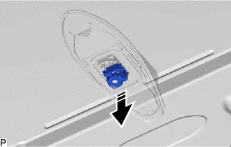
(d) Remove the telephone and GPS antenna assembly with cover as shown in the illustration.
|
|
Remove in this Direction |
3. REMOVE TELEPHONE AND GPS ANTENNA ASSEMBLY
(a) Pull the telephone and GPS antenna assembly in the direction indicated by the arrow (1) shown in the illustration to disengage the 3 claws and 2 guides.
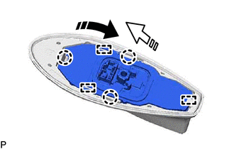
|
|
Remove in this Direction (1) |
 |
Remove in this Direction (2) |
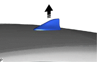
(b) Pull the telephone and GPS antenna assembly in the direction indicated by the arrow (2) shown in the illustration to disengage the guide and remove the telephone and GPS antenna assembly.
(c) When reusing the telephone and GPS antenna assembly:
| (1) Remove the seal. |
|
Toyota Avalon (XX50) 2019-2022 Service & Repair Manual > Suspension Control: Absorber Control Switch
ComponentsCOMPONENTS ILLUSTRATION *1 ABSORBER CONTROL SWITCH (ELECTRIC PARKING BRAKE SWITCH ASSEMBLY) - - InspectionINSPECTION PROCEDURE 1. INSPECT ABSORBER CONTROL SWITCH (ELECTRIC PARKING BRAKE SWITCH ASSEMBLY) (a) Measure the resistance according to the value(s) in the table below. Standard Resi ...