DESCRIPTION
The certification ECU (smart key ECU assembly) has a power source mode switching function.
This DTC is stored when the IGE input (the steering lock motor activation permission signal) sent directly from the certification ECU (smart key ECU assembly) to the steering lock ECU (steering lock actuator or upper bracket assembly) is determined to be abnormal.
HINT:
The steering lock ECU (steering lock actuator or upper bracket assembly) is not connected to the CAN communication system. However, the steering lock ECU (steering lock actuator or upper bracket assembly) is connected to the certification ECU (smart key ECU assembly) via LIN communication and communicates with other components via CAN communication through the certification ECU (smart key ECU assembly).
|
DTC No. | Detection Item |
DTC Detection Condition | Trouble Area |
Note |
|---|---|---|---|---|
| B2782 |
Power Source Control ECU Malfunction |
Either of the following conditions is met (1-trip detection logic (Only output while a malfunction is present and the power switch is on (IG).)):
HINT: If the power supply signal from the LIN communication line does not match the power supply signal from the direct line, the system is determined to be malfunctioning. |
| DTC Output Confirmation Operation:
|
|
Vehicle Condition when Malfunction Detected |
Fail-safe Function when Malfunction Detected |
|---|---|
|
The steering cannot be locked or unlocked. For this reason, the hybrid control system cannot be started. |
Prohibits the hybrid control system from being started (the hybrid control system does not start). |
|
DTC No. | Data List and Active Test |
|---|---|
|
B2782 | - |
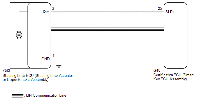
WIRING DIAGRAM
CAUTION / NOTICE / HINT
NOTICE:
Click here 
Click here
Click here
PROCEDURE
|
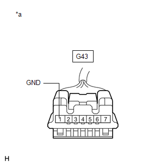
1. | CHECK HARNESS AND CONNECTOR (GROUND) |
(a) Disconnect the G43 steering lock ECU (steering lock actuator or upper bracket assembly) connector.
| (b) Measure the resistance according to the value(s) in the table below. Standard Resistance:
|
|
| NG |  | REPAIR OR REPLACE HARNESS OR CONNECTOR |
|
| 2. |
CHECK STEERING LOCK ECU (STEERING LOCK ACTUATOR OR UPPER BRACKET ASSEMBLY) |
(a) Connect the G43 steering lock ECU (steering lock actuator or upper bracket assembly) connector.
(b) Move the shift lever to P and turn the power switch off.
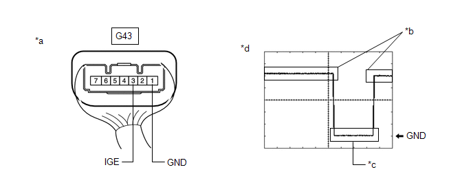
(c) Check the signal waveform according to the condition(s) in the table below.
|
*a | Component with harness connected (Steering Lock ECU (Steering Lock Actuator or Upper Bracket Assembly)) |
*b | Steering lock motor not operating |
|
*c | Steering lock motor operating |
*d | Waveform |
OK:
|
Tester Connection | Condition |
Tool Setting | Specified Condition |
|---|---|---|---|
|
G43-3 (IGE) - G43-1 (GND) |
2 V/DIV., 200 ms./DIV. |
Steering lock motor not operating → Operating → Not operating |
Pulse generation (See waveform) |
HINT:
| NG | | GO TO STEP 5 |
|
| 3. |
CLEAR DTC AND DATA LIST MALFUNCTION RECORD |
(a) Clear the DTCs.
Body Electrical > Smart Key > Clear DTCs(b) Disconnect the cable from the negative (-) auxiliary battery terminal, wait for 30 seconds or more, and then reconnect the cable to the negative (-) auxiliary battery terminal to clear the record of malfunctions stored in the Data List.
CAUTION:
After turning the power switch off, waiting time may be required before disconnecting the cable from the auxiliary battery terminal. Therefore, make sure to read the disconnecting the cable from the auxiliary battery terminal notices before proceeding with work.
Click here
|
| 4. |
CHECK FOR DTC |
(a) Perform the DTC output confirmation operation.
(b) Check if DTC B2782 is output.
Body Electrical > Smart Key > Trouble Codes|
Result | Proceed to |
|---|---|
|
DTC B2782 is not output. |
A |
| DTC B2782 is output. |
B |
| A |
| SYSTEM RETURNED TO NORMAL (DTC STORED DUE TO BAD CONNECTION, BUT SYSTEM RETURNED TO NORMAL BY RECONNECTING CONNECTOR) |
| B |
| REPLACE STEERING LOCK ECU (STEERING LOCK ACTUATOR OR UPPER BRACKET ASSEMBLY) |
| 5. |
CHECK HARNESS AND CONNECTOR (STEERING LOCK ECU (STEERING LOCK ACTUATOR OR UPPER BRACKET ASSEMBLY) - CERTIFICATION ECU (SMART KEY ECU ASSEMBLY)) |
(a) Disconnect the G43 steering lock ECU (steering lock actuator or upper bracket assembly) connector.
(b) Disconnect the G40 certification ECU (smart key ECU assembly) connector.
(c) Check for deformation and corrosion of the connector case and terminals.
OK:
There is no deformation or corrosion of the connector case or terminals.
(d) Measure the resistance according to the value(s) in the table below.
Standard Resistance:
|
Tester Connection | Condition |
Specified Condition |
|---|---|---|
|
G43-3 (IGE) - G40-25 (SLR+) |
Always | Below 1 Ω |
|
G43-3 (IGE) or G40-25 (SLR+) - Other terminals and body ground |
Always | 10 kΩ or higher |
| OK | | REPLACE CERTIFICATION ECU (SMART KEY ECU ASSEMBLY) |
| NG | | REPAIR OR REPLACE HARNESS OR CONNECTOR |
DESCRIPTION
When an open or short circuit is detected in the transponder key amplifier coil built into the power switch, the certification ECU (smart key ECU assembly) stores this DTC. This DTC is also stored as a history DTC.
|
DTC No. | Detection Item |
DTC Detection Condition | Trouble Area |
Note |
|---|---|---|---|---|
| B2784 |
Antenna Coil Open / Short |
The transponder key amplifier coil built into the power switch is open (see below) or shorted (determined by communication with certification ECU (smart key ECU assembly)). (1 trip detection logic*) |
| DTC output confirmation operation:
|
|
Vehicle Condition when Malfunction Detected |
Fail-safe Operation when Malfunction Detected |
|---|---|
|
Hybrid control system cannot be started when transmitter battery is depleted by holding electrical key transmitter sub-assembly near power switch and pressing and holding power switch with shift lever in P |
- |
|
DTC No. | Data List and Active Test |
|---|---|
|
B2784 | - |
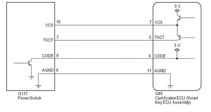
WIRING DIAGRAM
CAUTION / NOTICE / HINT
NOTICE:
Click here 
Click here
PROCEDURE
|
1. | CLEAR DTC |
(a) Clear the DTCs.
Body Electrical > Smart Key > Clear DTCs
|
| 2. |
CHECK FOR DTC |
(a) Perform "DTC Output Confirmation Operation" procedure.
(b) Check for DTCs.
Body Electrical > Smart Key > Trouble CodesOK:
DTC B2784 is not output.
| OK |  |
USE SIMULATION METHOD TO CHECK |
|
| 3. |
CHECK POWER SWITCH (OUTPUT) |
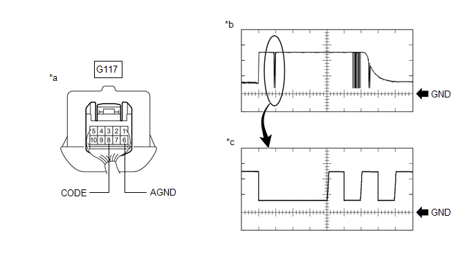
(a) Using an oscilloscope, check the waveform.
|
*a | Component with harness connected (Power Switch) | *b |
Waveform |
| *c |
Waveform (detail) | - |
- |
OK:
|
Tester Connection | Condition |
Tool Setting | Specified Condition |
|---|---|---|---|
|
G117-8 (CODE) - G117-6 (AGND) |
Power switch off, power switch pressed with electrical key transmitter sub-assembly held near power switch* |
1 V/DIV., 20 ms./DIV. |
Pulse generation (See waveform) |
|
2 V/DIV., 100 μs./DIV. |
Pulse generation (See waveform (detail)) |
OK:
The waveform is similar to that shown in the illustration.
| OK | | REPLACE CERTIFICATION ECU (SMART KEY ECU ASSEMBLY) |
| NG | | REPLACE POWER SWITCH |
DESCRIPTION
This DTC is stored when the steering lock ECU (steering lock actuator or upper bracket assembly) detects an IG2 power supply malfunction.
HINT:
The steering lock ECU (steering lock actuator or upper bracket assembly) is not connected to the CAN communication system. However, the steering lock ECU (steering lock actuator or upper bracket assembly) is connected to the certification ECU (smart key ECU assembly) via LIN communication and communicates with other components via CAN communication through the certification ECU (smart key ECU assembly).
|
DTC No. | Detection Item |
DTC Detection Condition | Trouble Area |
Note |
|---|---|---|---|---|
| B2788 |
IG2 Signal Malfunction |
Mismatch between the steering lock ECU (steering lock actuator or upper bracket assembly) IG2 input from the LIN communication system and from the direct line. (1-trip detection logic (Only output while a malfunction is present and the power switch is on (IG).)) |
| DTC Output Confirmation Operation:
|
|
Vehicle Condition when Malfunction Detected |
Fail-safe Function when Malfunction Detected |
|---|---|
|
The steering cannot be locked or unlocked. For this reason, the hybrid control system cannot be started. |
- |
|
DTC No. | Data List and Active Test |
|---|---|
|
B2788 | - |
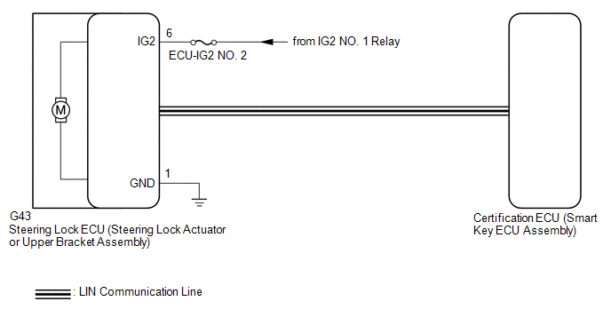
WIRING DIAGRAM
CAUTION / NOTICE / HINT
NOTICE:
Click here 
Click here
PROCEDURE
|
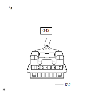
1. | CHECK HARNESS AND CONNECTOR (POWER SOURCE) |
(a) Disconnect the G43 steering lock ECU (steering lock actuator or upper bracket assembly) connector.
| (b) Measure the voltage according to the value(s) in the table below. Standard Voltage:
|
|
| NG |  | REPAIR OR REPLACE HARNESS OR CONNECTOR |
|
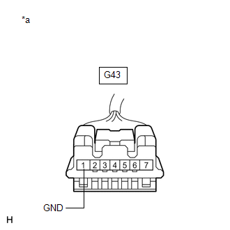
| 2. |
CHECK HARNESS AND CONNECTOR (GROUND) |
| (a) Measure the resistance according to the value(s) in the table below. Standard Resistance:
|
|
| OK | | REPLACE STEERING LOCK ECU (STEERING LOCK ACTUATOR OR UPPER BRACKET ASSEMBLY) |
| NG | | REPAIR OR REPLACE HARNESS OR CONNECTOR |
Toyota Avalon (XX50) 2019-2022 Service & Repair Manual > Can Communication System(for Gasoline Model): Blind Spot Monitor Sensor Communication Stop Mode. Center Airbag Sensor Communication Stop Mode. Certification ECU Communication Stop Mode
Blind Spot Monitor Sensor Communication Stop Mode DESCRIPTION Detection Item Symptom Trouble Area Blind Spot Monitor Sensor Communication Stop Mode Any of the following conditions are met: Communication stop for "Blind Spot Monitor Master" is indicated on the "Communication Bus Check" screen of the ...