DESCRIPTION When the theft
deterrent system is switched from the armed state to the alarm sounding
state, the main body ECU (multiplex network body ECU) transmits a signal
to cause the security horn assembly to sound at intervals of 0.4
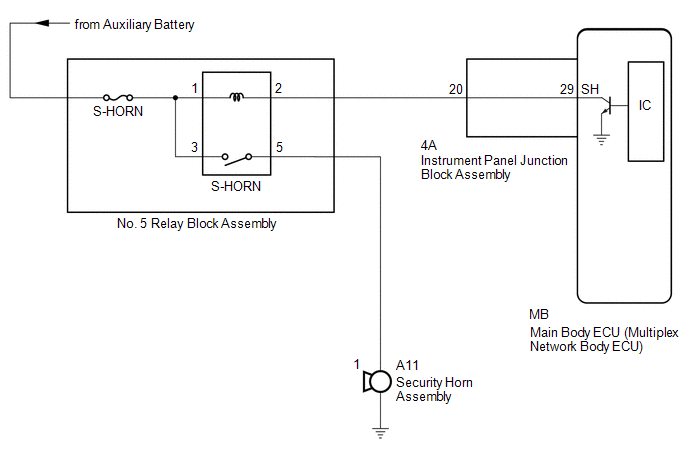
seconds. WIRING DIAGRAM
 CAUTION / NOTICE / HINT
NOTICE:
- Before replacing the main body ECU (multiplex network body ECU), refer to Registration.
Click here 
- Inspect the fuses for circuits related to this system before performing the following procedure.
PROCEDURE |
1. | PERFORM ACTIVE TEST USING TECHSTREAM (SECURITY HORN) |
(a) Connect the Techstream to the DLC3. (b) Turn the power switch on (IG).
(c) Turn the Techstream on. (d) Enter the following menus: Body Electrical / Main Body / Active Test.
(e) Perform the Active Test according to the display on the Techstream. Body Electrical > Main Body > Active Test
|
Tester Display | Measurement Item |
Control Range | Diagnostic Note | |
Security Horn | Security horn Assembly |
OFF/ON | - | Body Electrical > Main Body > Active Test
|
Tester Display | | Security Horn |
OK: The security horn assembly sounds and stops correctly when operated through the Techstream.
| OK |
 | REPLACE MAIN BODY ECU (MULTIPLEX NETWORK BODY ECU) |
|
NG |
 | |
| 2. |
INSPECT SECURITY HORN ASSEMBLY | (a) Remove the security horn assembly.
Click here (b) Inspect the security horn assembly.
Click here
| NG |
| REPLACE SECURITY HORN ASSEMBLY |
|
OK | |
| |
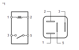
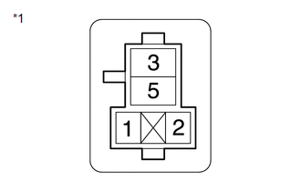
| (a) Remove the S-HORN relay from the No. 5 relay block. |
|
(b) Measure the resistance according to the value(s) in the table below.
Standard Resistance: |
Tester Connection | Condition |
Specified Condition | |
3 - 5 | Auxiliary battery voltage not applied between terminals 1 and 2 |
10 kΩ or higher | |
3 - 5 | Auxiliary battery voltage applied between terminals 1 and 2 |
Below 1 Ω |
| NG |
| REPLACE S-HORN RELAY |
|
OK | |
| |
| 4. |
INSPECT INSTRUMENT PANEL JUNCTION BLOCK ASSEMBLY |
(a) Remove the main body ECU (multiplex network body ECU). Click here
|
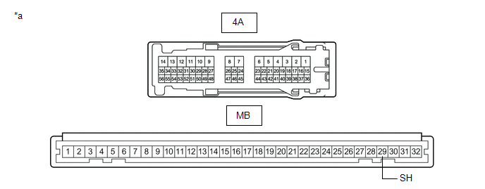
*a | Component without harness connected (Instrument Panel Junction Block Assembly) |
- | - |
(b) Disconnect the 4A instrument panel junction block assembly connector.
(c) Measure the resistance according to the value(s) in the table below.
Standard Resistance: |
Tester Connection | Condition |
Specified Condition | |
4A-20 - MB-29 (SH) | Always |
Below 1 Ω |
| NG |
| REPLACE INSTRUMENT PANEL JUNCTION BLOCK ASSEMBLY |
|
OK | |
| |
| 5. |
CHECK HARNESS AND CONNECTOR (AUXILIARY BATTERY - S-HORN RELAY) |
| (a) Measure the voltage according to the value(s) in the table below.
Standard Voltage: |
Tester Connection | Condition |
Specified Condition | |
No. 5 relay block S-HORN relay terminal 1 - Body ground |
Power switch off |
11 to 14 V | |
No. 5 relay block S-HORN relay terminal 3 - Body ground |
Power switch off |
11 to 14 V | | |
| NG |
| REPAIR OR REPLACE HARNESS OR CONNECTOR |
|
OK | |
| |
| 6. |
CHECK HARNESS AND CONNECTOR (S-HORN RELAY - SECURITY HORN ASSEMBLY) |
| (a) Measure the resistance according to the value(s) in the table below.
Standard Resistance: |
Tester Connection | Condition |
Specified Condition | |
No. 5 relay block S-HORN relay terminal 5 - A11-1 |
Always | Below 1 Ω | |
No. 5 relay block S-HORN relay terminal 5 or A11-1 - Other terminals and body ground |
Always | 10 kΩ or higher | |
|
| NG |
| REPAIR OR REPLACE HARNESS OR CONNECTOR |
|
OK | |
| |
| 7. |
CHECK HARNESS AND CONNECTOR (S-HORN RELAY - INSTRUMENT PANEL JUNCTION BLOCK ASSEMBLY) |
| (a) Measure the resistance according to the value(s) in the table below.
Standard Resistance: |
Tester Connection | Condition |
Specified Condition | |
No. 5 relay block S-HORN relay terminal 2 - 4A-20 |
Always | Below 1 Ω | |
No. 5 relay block S-HORN relay terminal 2 or 4A-20 - Other terminals and body ground |
Always | 10 kΩ or higher | |
|
| OK |
| REPLACE MAIN BODY ECU (MULTIPLEX NETWORK BODY ECU) |
| NG |
| REPAIR OR REPLACE HARNESS OR CONNECTOR | |