ADJUSTMENT
PROCEDURE
1. PERFORM BLIND SPOT MONITOR BEAM AXIS CONFIRMATION
HINT:
The blind spot monitor beam axis confirmation is performed to confirm whether the sensor's beam axis is correct, and perform adjustment of the beam axis by using reflector.
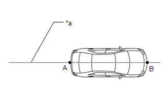
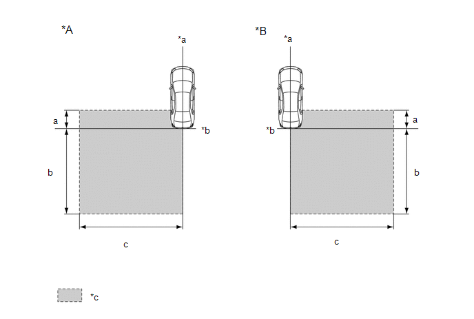
(a) When performing the blind spot monitor beam axis confirmation, move the vehicle to a place where the space shown in the illustration can be secured.
|
*A | Left Side Of Vehicle |
*B | Right Side Of Vehicle |
|
*a | Vehicle Center Line |
*b | Rear Bumper |
|
*c | Inspection Area |
- | - |
Standard:
|
Location | Measurement |
|---|---|
|
a | 1 m (3.28 ft.) |
|
b | 5 m (16.41 ft.) |
|
c | 6 m (19.68 ft.) |
NOTICE:
(b) Place the reflector.
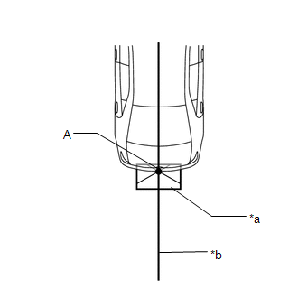
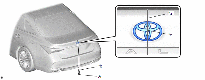
(1) Hang a weight with a pointed tip from the center of the rear emblem, and mark the rear center point of the vehicle (point A) on the ground.
|
*a | String |
*b | Weight |
|
*c | Center |
- | - |
HINT:
Lightly flick the string with your fingers several times to confirm that the string is aligned with mark A.
(2) Hang a weight with a pointed tip from the center of the radiator grille (or front panel) emblem, and mark the front center point of the vehicle (point B) on the ground.
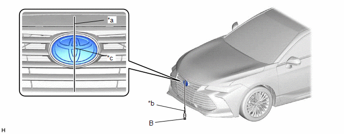
|
*a | String |
*b | Weight |
|
*c | Center |
- | - |
HINT:
Lightly flick the string with your fingers several times to confirm that the string is aligned with mark B.
| (3) Draw a vehicle center line so that it passes through mark A and B (front and rear center points). |
|
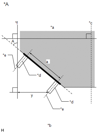
(4) Enlarge and print out the poster shown in the illustration.
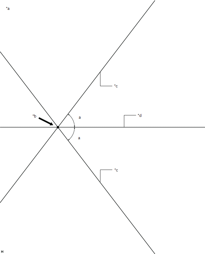
|
*a | Poster |
*b | Edge of Rear Bumper |
|
*c | Line C |
*d | Vehicle center line |
Standard:
|
Part | Angle |
|---|---|
|
a | 52.6° |
| (5) Attach the printed poster to the floor with the vehicle center line aligned with point A as shown in the illustration. |
|
| (6) Align a piece of string with line C and mark point D at a distance of 3373 mm (11.07 ft.) from point A. |
|
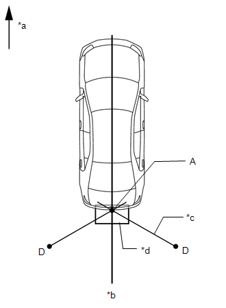
(7) Set the reflector at the point D shown in the illustration below.
SST: 09870-60000
09870-60010
SST: 09870-60040
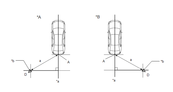
|
*A | Left Side Of Vehicle |
*B | Right Side Of Vehicle |
|
*a | Vehicle Center Line |
*b | Reflector |
Standard:
|
Part | Length |
|---|---|
|
a | 3373 mm (11.07 ft.) |
NOTICE:
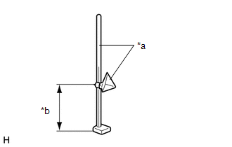
|
*a |
SST (reflector) |
|
*b |
596 mm (1.95 ft.) |
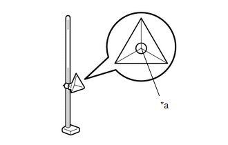
|
*a |
Center Of Triangular Pyramid |
(c) Perform the blind spot monitor beam axis display.
(1) Connect the GTS to the DLC3.
(2) Turn the engine switch on (IG).
(3) Turn the blind spot monitor system on.
(4) Turn the GTS on.
(5) Enter the following menus: Body Electrical / Blind Spot Monitor Master or Blind Spot Monitor Slave / Utility / BSM Master Beam Axis Display or BSM Slave Beam Axis Display.
HINT:
The master beam is on the RH side and the slave beam is on the LH side.
Body Electrical > Blind Spot Monitor Master > Utility|
Tester Display |
|---|
| BSM Master Beam Axis Display |
|
Tester Display |
|---|
| BSM Slave Beam Axis Display |
(6) Check the results displayed for the BSM beam axis display.
Allowable Range:
|
Item | Blind Spot Monitor Sensor RH |
Blind Spot Monitor Sensor LH |
|---|---|---|
|
Angle | -3.6 to +3.6° |
-3.6 to +3.6° |
HINT:
If the displayed results are outside the permissible range, the following are possible causes. Therefore, implement countermeasures, check the blind spot monitor beam axis and perform the procedure again.
|
Possible Causes | Countermeasure |
|---|---|
|
Incorrect SST (reflector) position |
Check the position of SST (reflector) and checking space and perform the procedure again |
|
A metallic object is located in the vicinity of the checking space |
Check the position of SST (reflector) and checking space and perform the procedure again |
|
The blind spot monitor sensor installation is abnormal |
Check the installation condition of the blind spot monitor sensor |
(d) Perform the blind spot monitor beam axis adjustment.
(1) Enter the following menus: Body Electrical / Blind Spot Monitor Master or Blind Spot Monitor Slave / Utility / BSM Master Beam Axis Adjustment or BSM Slave Beam Axis Adjustment.
Body Electrical > Blind Spot Monitor Master > Utility|
Tester Display |
|---|
| BSM Master Beam Axis Adjustment |
|
Tester Display |
|---|
| BSM Slave Beam Axis Adjustment |
HINT:
When values on the axis display are in the allowable range, performing this adjustment compensates for any deviation from the normal value.
2. PERFORM BLIND SPOT MONITOR SENSOR INSTALLATION CONDITION INSPECTION
NOTICE:
HINT:
The blind spot monitor sensor installation condition inspection is performed to confirm whether the sensor is perpendicular to the floor surface (+/-5°) by using a jig, and that the sensor is 46 to 54° from the line parallel to the vehicle center line.
(a) Remove the rear bumper assembly.
Click here 
(b) Attach a jig similar to the one shown in the illustration to the outward facing surface of the blind spot monitor sensor and check that the measurement or angle is within the allowable range to confirm that the blind spot monitor sensor is perpendicular to the floor surface (+/-5°).
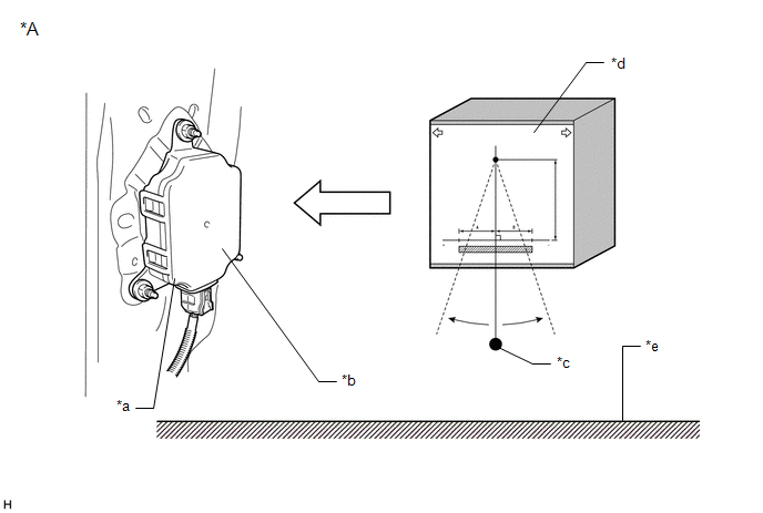
|
*A | Rear view of vehicle (RH): |
- | - |
|
*a | Blind Spot Monitor Sensor |
*b | Outward facing surface |
|
*c | Weight |
*d | Jig |
|
*e | Floor surface |
- | - |
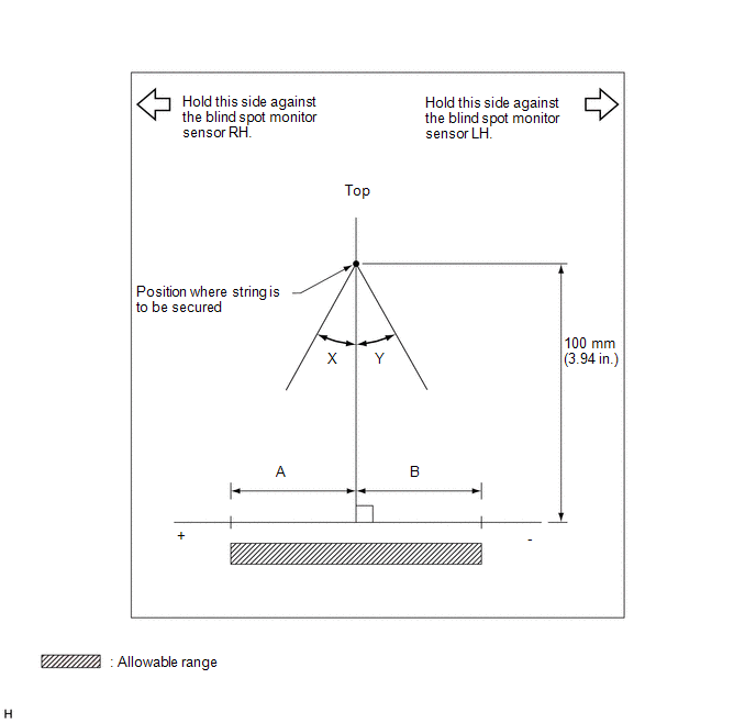
Standard:
|
A | B | |
|---|---|---|
|
Blind spot monitor sensor RH |
7 mm (0.276 in.) |
-7 mm (-0.276 in.) |
|
Blind spot monitor sensor LH |
7 mm (0.276 in.) |
-7 mm (-0.276 in.) |
|
X | Y | |
|---|---|---|
|
Blind spot monitor sensor RH |
5° | -5° |
|
Blind spot monitor sensor LH |
5° | -5° |
| (c) Using the sensor installation stud bolt center lines as a reference, check that the stud bolts are as shown in the illustration. Standard:
HINT: If the results are not as specified, it is possible that the blind spot monitor sensor installation area (frame, stud bolt) is deformed, so make corrections as necessary. |
|
COMPONENTS
ILLUSTRATION
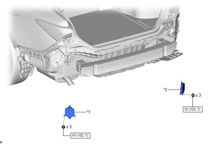
|
*1 | BLIND SPOT MONITOR SENSOR LH |
*2 | BLIND SPOT MONITOR SENSOR RH |
 |
N*m (kgf*cm, ft.*lbf): Specified torque |
- | - |
INSTALLATION
CAUTION / NOTICE / HINT
NOTICE:
HINT:
PROCEDURE
1. INSTALL BLIND SPOT MONITOR SENSOR LH
(a) Connect the connector.
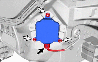
(b) Install the blind spot monitor sensor LH with the 3 nuts.
Torque:
10 N·m {102 kgf·cm, 7 ft·lbf}
2. INSTALL BLIND SPOT MONITOR SENSOR RH
(a) Connect the connector.
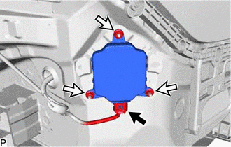
(b) Install the blind spot monitor sensor RH with the 3 nuts.
Torque:
10 N·m {102 kgf·cm, 7 ft·lbf}
3. PERFORM BLIND SPOT MONITOR SENSOR INSTALLATION CONDITION INSPECTION
Click here 
4. INSTALL REAR BUMPER ASSEMBLY
Click here
5. PERFORM BLIND SPOT MONITOR BEAM AXIS CONFIRMATION
Click here
6. PERFORM DIAGNOSTIC SYSTEM CHECK
for Gasoline Model: Click here
for HV Model: Click here
REMOVAL
CAUTION / NOTICE / HINT
The necessary procedures (adjustment, calibration, initialization, or registration) that must be performed after parts are removed and installed, or replaced during blind spot monitor sensor removal/installation are shown below.
Necessary Procedure After Parts Removed/Installed/Replaced (for Gasoline Model)|
Replaced Part or Performed Procedure |
Necessary Procedure | Effect/Inoperative Function When Necessary Procedures are not Performed |
Link |
|---|---|---|---|
| Blind spot monitor sensor |
Blind spot monitor beam axis adjustment |
|
|
|
Rear bumper assembly |
|
|
|
|
Replaced Part or Performed Procedure |
Necessary Procedure | Effect/Inoperative Function When Necessary Procedures are not Performed |
Link |
|---|---|---|---|
| Blind spot monitor sensor |
Blind spot monitor beam axis adjustment |
|
|
|
Rear bumper assembly |
|
|
|
PROCEDURE
1. REMOVE REAR BUMPER ASSEMBLY
Click here

2. REMOVE BLIND SPOT MONITOR SENSOR LH
| (a) Disconnect the connector. |
|
(b) Remove the 3 nuts and blind spot monitor sensor LH.
NOTICE:
Replace the blind spot monitor sensor LH if it has been dropped or subjected to a severe impact.
3. REMOVE BLIND SPOT MONITOR SENSOR RH
| (a) Disconnect the connector. |
|
(b) Remove the 3 nuts and blind spot monitor sensor RH.
NOTICE:
Replace the blind spot monitor sensor RH if it has been dropped or subjected to a severe impact.
Toyota Avalon (XX50) 2019-2022 Service & Repair Manual > Sfi System: Barometric Pressure Sensor "A" Circuit Short to Ground (P222611,P222615). A/F (O2) Sensor Signal Biased/Stuck Lean Bank 1 Sensor 2 Circuit Current Above Threshold (P227019,P227118). ECM/PCM Engine Off
Barometric Pressure Sensor "A" Circuit Short to Ground (P222611,P222615) DESCRIPTION The atmospheric pressure sensor is built into the ECM. The ECM provides optimal control in response to atmospheric pressure fluctuations. DTC No. Detection Item DTC Detection Condition Trouble Area MIL Memory Note P ...