DESCRIPTION
When a stop light relay circuit malfunction signal sent from the electronically controlled brake system is detected by the clearance warning ECU assembly, DTC C1A4B is stored.
|
DTC No. | Detection Item |
DTC Detection Condition | Trouble Area |
|---|---|---|---|
|
C1A4B | Stop Light Relay Circuit |
Stop light relay circuit malfunction |
Electronically controlled brake system |
CAUTION / NOTICE / HINT
NOTICE:
Click here 
Click here
for Gasoline Model with Cornering Light: Click here
for Gasoline Model without Cornering Light: Click here
PROCEDURE
|
1. | CHECK DTC OUTPUT |
(a) Using the Techstream, check for DTCs according to the prompts on the screen.
HINT:
After turning the engine switch from off to on (IG), wait 4 seconds or more before checking for DTCs.
Body Electrical > Advanced Parking Guidance/ICS/Intuitive P/A > Trouble Codes(b) Clear the DTCs according to the screen on the Techstream.
Body Electrical > Advanced Parking Guidance/ICS/Intuitive P/A > Clear DTCs(c) Recheck for DTCs.
Body Electrical > Advanced Parking Guidance/ICS/Intuitive P/A > Trouble CodesHINT:
Click here
|
Result | Proceed to |
|---|---|
|
DTC C1A4B is output | A |
|
DTC C1A4B is not output |
B |
| A |
 | GO TO PRE-COLLISION SYSTEM |
| B |
| USE SIMULATION METHOD TO CHECK |
DESCRIPTION
When a EFI system malfunction signal sent by the ECM is detected by the clearance warning ECU assembly, DTC C1A40 is stored.
|
DTC No. | Detection Item |
DTC Detection Condition | Trouble Area |
|---|---|---|---|
|
C1A40 | ENG / EHV Device |
When the engine switch is on (IG), a EFI system malfunction signal is detected for 1 second or more. |
|
CAUTION / NOTICE / HINT
NOTICE:
Click here 
Click here
PROCEDURE
|
1. | CHECK DTC OUTPUT |
(a) Using the Techstream, check for DTCs according to the prompts on the screen.
HINT:
After turning the engine switch from off to on (IG), wait 4 seconds or more before checking for DTCs.
Body Electrical > Advanced Parking Guidance/ICS/Intuitive P/A > Trouble Codes(b) Clear the DTCs according to the screen on the Techstream.
Body Electrical > Advanced Parking Guidance/ICS/Intuitive P/A > Clear DTCs(c) Recheck for DTCs.
Body Electrical > Advanced Parking Guidance/ICS/Intuitive P/A > Trouble CodesHINT:
Click here
|
Result | Proceed to |
|---|---|
|
DTC C1A40 is output | A |
|
DTC C1A40 is not output |
B |
| A |
 | GO TO EFI SYSTEM |
| B |
| USE SIMULATION METHOD TO CHECK |
DESCRIPTION
When an vehicle stability control system malfunction signal sent from the skid control ECU is detected by the clearance warning ECU assembly, DTC C1A50 is stored.
|
DTC No. | Detection Item |
DTC Detection Condition | Trouble Area |
|---|---|---|---|
|
C1A50 | Brake System |
When the engine switch is on (IG), a VSC warning light malfunction signal is detected for 1 second or more. |
|
CAUTION / NOTICE / HINT
NOTICE:
Click here 
Click here
PROCEDURE
|
1. | CHECK DTC OUTPUT |
(a) Using the Techstream, check for DTCs according to the prompts on the screen.
HINT:
After turning the engine switch from off to on (IG), wait 4 seconds or more before checking for DTCs.
Body Electrical > Advanced Parking Guidance/ICS/Intuitive P/A > Trouble Codes(b) Clear the DTCs according to the screen on the Techstream.
Body Electrical > Advanced Parking Guidance/ICS/Intuitive P/A > Clear DTCs(c) Recheck for DTCs.
Body Electrical > Advanced Parking Guidance/ICS/Intuitive P/A > Trouble CodesHINT:
Click here
|
Result | Proceed to |
|---|---|
|
DTC C1A50 is output | A |
|
DTC C1A50 is not output |
B |
| A |
 | GO TO ELECTRONICALLY CONTROLLED BRAKE SYSTEM |
| B |
| USE SIMULATION METHOD TO CHECK |
DESCRIPTION
When the clearance warning ECU assembly detects that the steering angle neutral point memorization is incomplete during self diagnosis, C1AEA is stored.
|
DTC No. | Detection Item |
DTC Detection Condition | Trouble Area |
|---|---|---|---|
|
C1AEA | Steering Angle Midpoint Initial Setting Incomplete |
Steering angle neutral point memorization incomplete |
|
CAUTION / NOTICE / HINT
NOTICE:
Click here 
Click here
PROCEDURE
|
1. | PERFORM CALIBRATION |
(a) Perform steering angle neutral point memorization.
Click here
|
| 2. |
CHECK FOR DTC |
(a) Using the Techstream, check for DTCs according to the prompts on the screen.
Body Electrical > Advanced Parking Guidance/ICS/Intuitive P/A > Trouble Codes(b) Clear the DTCs according to the screen on the Techstream.
Body Electrical > Advanced Parking Guidance/ICS/Intuitive P/A > Clear DTCs(c) Recheck for DTCs.
Body Electrical > Advanced Parking Guidance/ICS/Intuitive P/A > Trouble CodesHINT:
|
Result | Proceed to |
|---|---|
|
DTC C1AEA is output | A |
|
DTC C1AEA is not output |
B |
| A |
 | REPLACE CLEARANCE WARNING ECU ASSEMBLY |
| B |
| USE SIMULATION METHOD TO CHECK |
DESCRIPTION
When ICS detection area adjustment is incomplete, the clearance warning ECU assembly stores DTC C1AF0.
|
DTC No. | Detection Item |
DTC Detection Condition | Trouble Area |
|---|---|---|---|
|
C1AF0 | ICS Detection Area Adjustment Incomplete |
ICS detection area adjustment incomplete |
|
CAUTION / NOTICE / HINT
NOTICE:
Click here 
Click here
PROCEDURE
|
1. | INTELLIGENT CLEARANCE SONAR SYSTEM REGISTRATION |
(a) Perform intelligent clearance sonar system registration.
Click here
|
| 2. |
CHECK FOR DTC |
(a) Using the Techstream, check for DTCs according to the prompts on the screen.
Body Electrical > Advanced Parking Guidance/ICS/Intuitive P/A > Trouble Codes(b) Clear the DTCs according to the screen on the Techstream.
Body Electrical > Advanced Parking Guidance/ICS/Intuitive P/A > Clear DTCs(c) Recheck for DTCs.
Body Electrical > Advanced Parking Guidance/ICS/Intuitive P/A > Trouble CodesHINT:
If DTC C1AF0 is still output after performing intelligent clearance sonar system registration 3 times, replace the clearance warning ECU assembly.
|
Result | Proceed to |
|---|---|
|
DTC C1AF0 is output | A |
|
DTC C1AF0 is not output |
B |
| A |
 | REPLACE CLEARANCE WARNING ECU ASSEMBLY |
| B |
| USE SIMULATION METHOD TO CHECK |
DESCRIPTION
When it is judged that the front sensors have not been initialized, the clearance warning ECU assembly stores DTC C1AF3.
|
DTC No. | Detection Item |
DTC Detection Condition | Trouble Area |
|---|---|---|---|
|
C1AF3 | Fr Sensor Initialization Incomplete |
Front sensor not initialized |
|
CAUTION / NOTICE / HINT
NOTICE:
Click here 
Click here
PROCEDURE
|
1. | INITIALIZE FRONT CENTER ULTRASONIC SENSOR AND FRONT CORNER ULTRASONIC SENSOR |
(a) Initialize the front center ultrasonic sensor and front corner ultrasonic sensor.
Click here
|
| 2. |
CHECK FOR DTC |
(a) Using the Techstream, check for DTCs according to the prompts on the screen.
HINT:
After turning the engine switch from off to on (IG), wait 10 seconds or more before checking for DTCs.
Body Electrical > Advanced Parking Guidance/ICS/Intuitive P/A > Trouble Codes|
Result | Proceed to |
|---|---|
|
DTC C1AF3 is output | A |
|
DTC C1AF3 is not output |
B |
HINT:
If DTC C1AF3 is still output after initializing the front center ultrasonic sensor and front corner ultrasonic sensor 3 times, replace the clearance warning ECU assembly.
| A |  |
REPLACE CLEARANCE WARNING ECU ASSEMBLY |
| B |
| END (FRONT SENSORS WERE NOT INITIALIZED) |
DESCRIPTION
When it is judged that the rear sensors have not been initialized, the clearance warning ECU assembly stores DTC C1AF4.
|
DTC No. | Detection Item |
DTC Detection Condition | Trouble Area |
|---|---|---|---|
|
C1AF4 | Rr Sensor Initialization Incomplete |
Rear sensor not initialized |
|
CAUTION / NOTICE / HINT
NOTICE:
Click here 
Click here
PROCEDURE
|
1. | INITIALIZE REAR CENTER ULTRASONIC SENSOR AND REAR CORNER ULTRASONIC SENSOR |
(a) Initialize the rear center ultrasonic sensor and rear corner ultrasonic sensor.
Click here
|
| 2. |
CHECK FOR DTC |
(a) Using the Techstream, check for DTCs according to the prompts on the screen.
HINT:
After turning the engine switch from off to on (IG), wait 10 seconds or more before checking for DTCs.
Body Electrical > Advanced Parking Guidance/ICS/Intuitive P/A > Trouble Codes|
Result | Proceed to |
|---|---|
|
DTC C1AF4 is output | A |
|
DTC C1AF4 is not output |
B |
HINT:
if DTC C1AF4 is still output after initializing the rear center ultrasonic sensor and rear corner ultrasonic sensor 3 times, replace the clearance warning ECU assembly.
| A |  |
REPLACE CLEARANCE WARNING ECU ASSEMBLY |
| B |
| END (REAR SENSORS WERE NOT INITIALIZED) |
DESCRIPTION
This DTC is stored when the clearance warning ECU assembly receives a signal from the blind spot monitor system via CAN communication indicating a malfunction in the blind spot monitor sensor.
|
DTC No. | Detection Item |
DTC Detection Condition | Trouble Area |
|---|---|---|---|
|
C1AF7 | RCTB Sensor |
Blind spot monitor sensor malfunction |
Blind spot monitor system |
PROCEDURE
| 1. |
CHECK FOR DTC |
(a) Using the Techstream, check for DTCs according to the prompts on the screen.
HINT:
After turning the engine switch from off to on (IG), wait 4 seconds or more before checking for DTCs.
Body Electrical > Advanced Parking Guidance/ICS/Intuitive P/A > Trouble Codes(b) Clear the DTCs according to the screen on the Techstream.
Body Electrical > Advanced Parking Guidance/ICS/Intuitive P/A > Clear DTCs(c) Recheck for DTCs.
Body Electrical > Advanced Parking Guidance/ICS/Intuitive P/A > Trouble CodesHINT:
|
Result | Proceed to |
|---|---|
|
DTC C1AF7 is output | A |
|
DTC C1AF7 is not output |
B |
| A |
 | GO TO BLIND SPOT MONITOR SYSTEM |
| B |
| USE SIMULATION METHOD TO CHECK |
DESCRIPTION
This DTC is stored when the clearance warning ECU assembly receives a signal from the blind spot monitor system via CAN communication indicating that the beam axis inspection is incomplete.
|
DTC No. | Detection Item |
DTC Detection Condition | Trouble Area |
|---|---|---|---|
|
C1AF9 | Blind Spot Monitor Beam Axis Inspection Incomplete |
The clearance warning ECU assembly receives a signal indicating that the beam axis inspection is incomplete. |
Blind spot monitor system |
PROCEDURE
| 1. |
CHECK FOR DTC |
(a) Using the Techstream, check for DTCs according to the prompts on the screen.
HINT:
After turning the engine switch from off to on (IG), wait 4 seconds or more before checking for DTCs.
Body Electrical > Advanced Parking Guidance/ICS/Intuitive P/A > Trouble Codes(b) Clear the DTCs according to the screen on the Techstream.
Body Electrical > Advanced Parking Guidance/ICS/Intuitive P/A > Clear DTCs(c) Recheck for DTCs.
Body Electrical > Advanced Parking Guidance/ICS/Intuitive P/A > Trouble CodesHINT:
Click here 
|
Result | Proceed to |
|---|---|
|
DTC C1AF9 is output | A |
|
DTC C1AF9 is not output |
B |
| A |
 | GO TO BLIND SPOT MONITOR SYSTEM |
| B |
| USE SIMULATION METHOD TO CHECK |
DESCRIPTION
This DTC is stored when the clearance warning ECU assembly receives a signal from the blind spot monitor system via CAN communication indicating blind spot monitor beam axis misalignment.
|
DTC No. | Detection Item |
DTC Detection Condition | Trouble Area |
|---|---|---|---|
|
C1AFA | Blind Spot Monitor Beam Axis Misalignment |
The clearance warning ECU assembly receives a signal from blind spot monitor system indicating blind spot monitor beam axis misalignment. |
Blind spot monitor system |
PROCEDURE
| 1. |
CHECK FOR DTC |
(a) Using the Techstream, check for DTCs according to the prompts on the screen.
HINT:
After turning the engine switch from off to on (IG), wait 4 seconds or more before checking for DTCs.
Body Electrical > Advanced Parking Guidance/ICS/Intuitive P/A > Trouble Codes(b) Clear the DTCs according to the screen on the Techstream.
Body Electrical > Advanced Parking Guidance/ICS/Intuitive P/A > Clear DTCs(c) Recheck for DTCs.
Body Electrical > Advanced Parking Guidance/ICS/Intuitive P/A > Trouble CodesHINT:
Click here 
|
Result | Proceed to |
|---|---|
|
DTC C1AFA is output | A |
|
DTC C1AFA is not output |
B |
| A |
 | GO TO BLIND SPOT MONITOR SYSTEM |
| B |
| USE SIMULATION METHOD TO CHECK |
DESCRIPTION
The electronically controlled brake system receives intelligent clearance sonar system information from the clearance warning ECU assembly via CAN communication. When it is determined that there is a communication error between the skid control ECU and clearance warning ECU assembly, DTC C164B is stored.
|
DTC No. | Detection Item |
DTC Detection Condition | Trouble Area |
|---|---|---|---|
|
C164B | Communication Error From Clearance Sonar ECU to VSC |
A communication error between the skid control ECU and clearance warning ECU assembly is detected |
|
CAUTION / NOTICE / HINT
NOTICE:
Click here 
Click here
PROCEDURE
|
1. | CHECK DTC OUTPUT |
(a) Using the Techstream, check for DTCs according to the prompts on the screen.
HINT:
After turning the engine switch from off to on (IG), wait 4 seconds or more before checking for DTCs.
Body Electrical > Advanced Parking Guidance/ICS/Intuitive P/A > Trouble Codes(b) Clear the DTCs according to the screen on the Techstream.
Body Electrical > Advanced Parking Guidance/ICS/Intuitive P/A > Clear DTCs(c) Recheck for DTCs.
Body Electrical > Advanced Parking Guidance/ICS/Intuitive P/A > Trouble CodesHINT:
Click here
|
Result | Proceed to |
|---|---|
|
DTC C164B is output | A |
|
DTC C164B is not output |
B |
| B |
 | USE SIMULATION METHOD TO CHECK |
|
| 2. |
CHECK DTC OUTPUT |
(a) Using the Techstream, check for DTCs according to the prompts on the screen.
Chassis > ABS/VSC/TRAC > Trouble Codes|
Result | Proceed to |
|---|---|
|
DTC is not output | A |
|
DTC is output | B |
| B |
| GO TO ELECTRONICALLY CONTROLLED BRAKE SYSTEM |
|
| 3. |
REPLACE CLEARANCE WARNING ECU ASSEMBLY |
(a) Replace the clearance warning ECU assembly with a known good one.
Click here
|
| 4. |
CHECK DTC OUTPUT |
(a) Using the Techstream, check for DTCs according to the prompts on the screen.
Body Electrical > Advanced Parking Guidance/ICS/Intuitive P/A > Trouble Codes(b) Clear the DTCs according to the screen on the Techstream.
Body Electrical > Advanced Parking Guidance/ICS/Intuitive P/A > Clear DTCs(c) Recheck for DTCs.
Body Electrical > Advanced Parking Guidance/ICS/Intuitive P/A > Trouble Codes|
Result | Proceed to |
|---|---|
|
DTC C164B is output | A |
|
DTC C164B is not output |
B |
| A |
| REPLACE SKID CONTROL ECU |
| B |
| END (CLEARANCE WARNING ECU ASSEMBLY DEFECTIVE) |
DESCRIPTION
This DTC is stored when the clearance warning ECU assembly receives a wheel speed sensor (front speed sensor RH or front speed sensor LH, rear speed sensor RH or rear speed sensor LH) abnormality signal from the electronically controlled brake system via CAN communication.
|
DTC No. | Detection Item |
DTC Detection Condition | Trouble Area |
|---|---|---|---|
|
C164D | Wheel Speed Sensor Malfunction |
Front wheel speed sensor malfunction |
Electronically controlled brake system |
CAUTION / NOTICE / HINT
NOTICE:
Click here 
Click here
PROCEDURE
|
1. | CHECK DTC OUTPUT |
(a) Using the Techstream, check for DTCs according to the prompts on the screen.
HINT:
After turning the engine switch from off to on (IG), wait 4 seconds or more before checking for DTCs.
Body Electrical > Advanced Parking Guidance/ICS/Intuitive P/A > Trouble Codes(b) Clear the DTCs according to the screen on the Techstream.
Body Electrical > Advanced Parking Guidance/ICS/Intuitive P/A > Clear DTCs(c) Recheck for DTCs.
Body Electrical > Advanced Parking Guidance/ICS/Intuitive P/A > Trouble CodesHINT:
Click here
|
Result | Proceed to |
|---|---|
|
DTC C164D is output | A |
|
DTC C164D is not output |
B |
| A |
 | GO TO ELECTRONICALLY CONTROLLED BRAKE SYSTEM |
| B |
| USE SIMULATION METHOD TO CHECK |
DESCRIPTION
When a stop light switch assembly circuit malfunction signal sent from the electronically controlled brake system is detected by the clearance warning ECU assembly, DTC C164E is stored.
|
DTC No. | Detection Item |
DTC Detection Condition | Trouble Area |
|---|---|---|---|
|
C164E | Stop Switch Circuit Malfunction |
Stop light switch assembly circuit open |
Electronically controlled brake system |
CAUTION / NOTICE / HINT
NOTICE:
Click here 
Click here
PROCEDURE
|
1. | CHECK DTC OUTPUT |
(a) Using the Techstream, check for DTCs according to the prompts on the screen.
HINT:
After turning the engine switch from off to on (IG), wait 4 seconds or more before checking for DTCs.
Body Electrical > Advanced Parking Guidance/ICS/Intuitive P/A > Trouble Codes(b) Clear the DTCs according to the screen on the Techstream.
Body Electrical > Advanced Parking Guidance/ICS/Intuitive P/A > Clear DTCs(c) Recheck for DTCs.
Body Electrical > Advanced Parking Guidance/ICS/Intuitive P/A > Trouble CodesHINT:
Click here
|
Result | Proceed to |
|---|---|
|
DTC C164E is output | A |
|
DTC C164E is not output |
B |
| A |
 | GO TO ELECTRONICALLY CONTROLLED BRAKE SYSTEM |
| B |
| USE SIMULATION METHOD TO CHECK |
DESCRIPTION
When a malfunction signal sent from the skid control ECU via CAN communication is detected by the clearance warning ECU assembly, DTC C164F is stored.
|
DTC No. | Detection Item |
DTC Detection Condition | Trouble Area |
|---|---|---|---|
|
C164F | Brake Hydraulic Pressure Malfunction |
Brake master cylinder brake fluid pressure abnormal |
Electronically controlled brake system |
CAUTION / NOTICE / HINT
NOTICE:
Click here 
Click here
PROCEDURE
|
1. | CHECK DTC OUTPUT |
(a) Using the Techstream, check for DTCs according to the prompts on the screen.
HINT:
After turning the engine switch from off to on (IG), wait 4 seconds or more before checking for DTCs.
Body Electrical > Advanced Parking Guidance/ICS/Intuitive P/A > Trouble Codes(b) Clear the DTCs according to the screen on the Techstream.
Body Electrical > Advanced Parking Guidance/ICS/Intuitive P/A > Clear DTCs(c) Recheck for DTCs.
Body Electrical > Advanced Parking Guidance/ICS/Intuitive P/A > Trouble CodesHINT:
Click here
|
Result | Proceed to |
|---|---|
|
DTC C164F is output | A |
|
DTC C164F is not output |
B |
| A |
 | GO TO ELECTRONICALLY CONTROLLED BRAKE SYSTEM |
| B |
| USE SIMULATION METHOD TO CHECK |
DESCRIPTION
If the vehicle information stored in the main body ECU (multiplex network body ECU) which is sent via CAN communication during the clearance warning ECU assembly self-diagnosis does not match that of clearance warning ECU assembly, DTC C168D is stored.
|
DTC No. | Detection Item |
DTC Detection Condition | Trouble Area |
|---|---|---|---|
|
C168D | Vehicle Information Unmatched |
Vehicle information does not match |
|
CAUTION / NOTICE / HINT
NOTICE:
Click here 
Click here
PROCEDURE
|
1. | REGISTER VEHICLE INFORMATION |
(a) Perform the following procedure to register the vehicle information.
Click here
|
| 2. |
CHECK FOR DTC |
(a) Using the Techstream, check for DTCs according to the prompts on the screen.
HINT:
After turning the engine switch from off to on (IG), wait 4 seconds or more before checking for DTCs.
Body Electrical > Advanced Parking Guidance/ICS/Intuitive P/A > Trouble Codes(b) Clear the DTCs according to the screen on the Techstream.
Body Electrical > Advanced Parking Guidance/ICS/Intuitive P/A > Clear DTCs(c) Recheck for DTCs.
Body Electrical > Advanced Parking Guidance/ICS/Intuitive P/A > Trouble CodesHINT:
If DTC C168D is still output after registering the vehicle information 3 times, replace the clearance warning ECU assembly.
|
Result | Proceed to |
|---|---|
|
DTC C168D is output | A |
|
DTC C168D is not output |
B |
| A |
 | REPLACE CLEARANCE WARNING ECU ASSEMBLY |
| B |
| USE SIMULATION METHOD TO CHECK |
DESCRIPTION
If the clearance warning ECU assembly detects an internal malfunction during self-diagnosis, DTC C1611 is stored.
|
DTC No. | Detection Item |
DTC Detection Condition | Trouble Area |
|---|---|---|---|
|
C1611 | ECU Malfunction |
| Clearance warning ECU assembly |
CAUTION / NOTICE / HINT
NOTICE:
Click here 
Click here
PROCEDURE
|
1. | CHECK DTC OUTPUT |
(a) Using the Techstream, check for DTCs according to the prompts on the screen.
HINT:
After turning the engine switch from off to on (IG), wait 3 seconds or more before checking for DTCs.
Body Electrical > Advanced Parking Guidance/ICS/Intuitive P/A > Trouble Codes(b) Clear the DTCs according to the screen on the Techstream.
Body Electrical > Advanced Parking Guidance/ICS/Intuitive P/A > Clear DTCs(c) Recheck for DTCs.
Body Electrical > Advanced Parking Guidance/ICS/Intuitive P/A > Trouble Codes|
Result | Proceed to |
|---|---|
|
DTC C1611 is output | A |
|
DTC C1611 is not output |
B |
| A |
 | REPLACE CLEARANCE WARNING ECU ASSEMBLY |
| B |
| USE SIMULATION METHOD TO CHECK |
DESCRIPTION
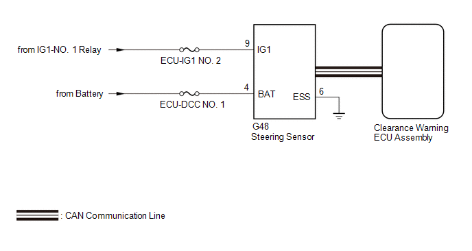
This DTC is stored if the clearance warning ECU assembly receives a signal via CAN communication from the steering sensor that indicates a power supply problem.
|
DTC No. | Detection Item |
DTC Detection Condition | Trouble Area |
|---|---|---|---|
|
C1625 | Open or Short in Steering Angle Sensor +B |
Open or short in steering sensor power source |
|
WIRING DIAGRAM
CAUTION / NOTICE / HINT
NOTICE:
Click here 
Click here
PROCEDURE
|
1. | CHECK HARNESS AND CONNECTOR (STEERING SENSOR POWER SOURCE) |
(a) Disconnect the G48 steering sensor connector.
(b) Measure the voltage according to the value(s) in the table below.
Standard Voltage:
|
Tester Connection | Condition |
Specified Condition |
|---|---|---|
|
G48-9 (IG1) - G48-6 (ESS) |
Engine switch on (IG) |
11 to 14 V |
| NG |  | REPAIR OR REPLACE HARNESS OR CONNECTOR |
|
| 2. |
CHECK HARNESS AND CONNECTOR (STEERING SENSOR POWER SOURCE) |
(a) Measure the resistance according to the value(s) in the table below.
Standard Resistance:
|
Tester Connection | Condition |
Specified Condition |
|---|---|---|
|
G48-6 (ESS) - Body ground |
Always | Below 1 Ω |
(b) Measure the voltage according to the value(s) in the table below.
Standard Voltage:
|
Tester Connection | Condition |
Specified Condition |
|---|---|---|
|
G48-4 (BAT) - G48-6 (ESS) |
Always | 11 to 14 V |
| OK | | REPLACE STEERING SENSOR |
| NG | | REPAIR OR REPLACE HARNESS OR CONNECTOR |
DESCRIPTION
This DTC is stored if the clearance warning ECU assembly receives a signal via CAN communication from the steering sensor that indicates an internal malfunction.
|
DTC No. | Detection Item |
DTC Detection Condition | Trouble Area |
|---|---|---|---|
|
C1626 | Steering Angle Sensor Failure |
A fail flag is transmitted from the steering sensor |
|
CAUTION / NOTICE / HINT
NOTICE:
Click here 
Click here
PROCEDURE
|
1. | REPLACE STEERING SENSOR |
(a) Replace the steering sensor with a new or known good one.
Click here
|
| 2. |
CHECK DTC OUTPUT |
(a) Using the Techstream, check for DTCs according to the prompts on the screen.
HINT:
After turning the engine switch from off to on (IG), wait 4 seconds or more before
Body Electrical > Advanced Parking Guidance/ICS/Intuitive P/A > Trouble Codes(b) Clear the DTCs according to the screen on the Techstream.
Body Electrical > Advanced Parking Guidance/ICS/Intuitive P/A > Clear DTCs(c) Recheck for DTCs.
|
Result | Proceed to |
|---|---|
|
DTC C1626 is output | A |
|
DTC C1626 is not output |
B |
| A |
 | REPLACE CLEARANCE WARNING ECU ASSEMBLY |
| B |
| END (STEERING SENSOR DEFECTIVE) |
DESCRIPTION
The clearance warning sonar ECU assembly communicates with the airbag ECU assembly (yaw rate and acceleration sensor) via CAN communication, and if it is determined that the airbag ECU assembly (yaw rate and acceleration sensor) is malfunctioning, DTC C1647 is stored.
|
DTC No. | Detection Item |
DTC Detection Condition | Trouble Area |
|---|---|---|---|
|
C1647 | G Sensor Failure |
Airbag ECU assembly malfunction |
Electronically controlled brake system |
CAUTION / NOTICE / HINT
NOTICE:
Click here 
Click here
PROCEDURE
|
1. | CHECK DTC OUTPUT |
(a) Using the Techstream, check for DTCs according to the prompts on the screen.
Body Electrical > Advanced Parking Guidance/ICS/Intuitive P/A > Trouble Codes(b) Clear the DTCs according to the screen on the Techstream.
Body Electrical > Advanced Parking Guidance/ICS/Intuitive P/A > Clear DTCs(c) Recheck for DTCs.
Body Electrical > Advanced Parking Guidance/ICS/Intuitive P/A > Trouble CodesHINT:
Click here
|
Result | Proceed to |
|---|---|
|
DTC C1647 is output | A |
|
DTC C1647 is not output |
B |
| A |
 | GO TO ELECTRONICALLY CONTROLLED BRAKE SYSTEM |
| B |
| USE SIMULATION METHOD TO CHECK |
DESCRIPTION
When a malfunction signal sent from the air conditioning system via CAN communication is detected by the clearance warning ECU assembly, DTC C1652 is stored.
|
DTC No. | Detection Item |
DTC Detection Condition | Trouble Area |
|---|---|---|---|
|
C1652 | Outside Air Temperature Sensor |
Ambient temperature sensor malfunction |
Air conditioning system |
CAUTION / NOTICE / HINT
NOTICE:
Click here 
Click here
PROCEDURE
|
1. | CHECK AIR CONDITIONING SYSTEM |
(a) Using the Techstream, check for DTCs according to the prompts on the screen.
HINT:
After turning the engine switch from off to on (IG), wait 13 seconds or more before checking for DTCs.
Body Electrical > Advanced Parking Guidance/ICS/Intuitive P/A > Trouble Codes(b) Clear the DTCs according to the screen on the Techstream.
Body Electrical > Advanced Parking Guidance/ICS/Intuitive P/A > Clear DTCs(c) Recheck for DTCs.
Body Electrical > Advanced Parking Guidance/ICS/Intuitive P/A > Trouble CodesHINT:
Click here
|
Result | Proceed to |
|---|---|
|
DTC C1652 is output | A |
|
DTC C1652 is not output |
B |
| A |
 | GO TO AIR CONDITIONING SYSTEM |
| B |
| USE SIMULATION METHOD TO CHECK |
CALIBRATION
NOTICE:
When any of the following parts have been replaced, perform adjustment shown in the following table. If not, the intelligent clearance sonar system may not operate correctly.
PRECAUTION (PROCEDURE 1)
(a) The necessary procedures (adjustment, calibration, initialization or registration) that must be performed after parts are removed and installed, or replaced during intelligent clearance sonar system removal/installation are shown below.
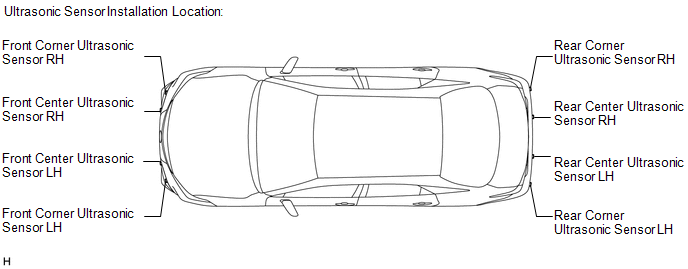
For the installation location of the ultrasonic sensors, refer to Parts Location.
Click here 
|
Part Name | Operation |
Adjustment Item | Proceed to |
|---|---|---|---|
|
Steering sensor |
| Steering angle neutral point (Initialize intelligent clearance sonar system) |
Procedure 4 |
| Suspension, tires, etc. |
The vehicle height changes because of suspension or tire replacement |
Measurement of ultrasonic sensor detection angle |
Procedure 2, 3 |
| Ultrasonic sensor detection angle registration |
Procedure 4 | ||
| Front bumper assembly |
| Measurement of ultrasonic sensor detection angle |
Procedure 2, 3 |
| Ultrasonic sensor detection angle registration |
Procedure 4 | ||
| Rear bumper assembly |
| Measurement of ultrasonic sensor detection angle |
Procedure 2, 3 |
| Ultrasonic sensor detection angle registration |
Procedure 4 | ||
| Clearance warning ECU assembly |
Replacement | Measurement of ultrasonic sensor detection angle |
Procedure 2, 3 |
| Steering angle neutral point |
Procedure 4 | ||
| Bumper type registration | |||
|
Ultrasonic sensor detection angle registration | |||
|
Ultrasonic sensor |
| Measurement of ultrasonic sensor detection angle |
Procedure 2, 3 |
| Ultrasonic sensor detection angle registration |
Procedure 4 | ||
| An ultrasonic sensor becomes misaligned |
Measurement of ultrasonic sensor detection angle |
Procedure 2, 3 | |
| Ultrasonic sensor detection angle registration |
Procedure 4 | ||
| An ultrasonic sensor is subjected to impact |
Measurement of ultrasonic sensor detection angle |
Procedure 2, 3 | |
| Ultrasonic sensor detection angle registration |
Procedure 4 | ||
| Battery |
Cable is disconnected from the negative (-) battery terminal |
Steering angle neutral point* |
Procedure 4 |
Click here
PREPARATION (PROCEDURE 2)
(a) Preparation
SST: 09989-00020
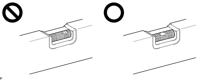
(b) Confirm levelness of floor surface.
(1) Place a bubble level on a level surface and confirm that the bubble is centered.
NOTICE:
Make sure that there is no gravel, sand, etc., and that the surface is not undulating.
HINT:
By adjusting the direction of the bubble level, it is possible to find a position where the bubble is centered.
(2) Turn on the digital angle gauge.
(3) Place the digital angle gauge in the same location and direction as that of the bubble level where the levelness of the surface was confirmed.
NOTICE:
Confirm that the location and direction of the digital angle gauge is exactly the same as that of the bubble level.
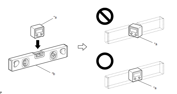
|
*a | Digital Angle Gauge |
*b | Level |
(4) Press the "ZERO" switch to memorize the zero point (perfectly level).
NOTICE:
Make sure that the digital angle gauge does not move when pressing the switch. If the digital angle gauge moves when the switch is pressed, an incorrect zero point may be memorized and it will not be possible to accurately check for levelness.
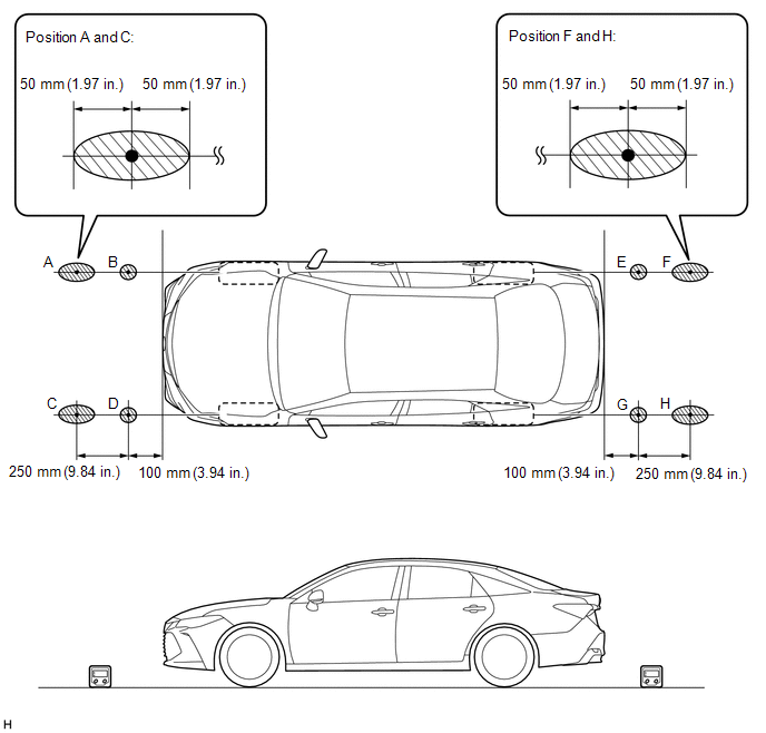
(5) Using the digital angle gauge in which the zero point (perfectly level) has been memorized, measure the angle of the floor surface at the 4 positions at the front of the vehicle and the 4 positions at the rear of the vehicle as shown in the illustration. Write the measured values into the following worksheet.
NOTICE:
HINT:
If necessary, the digital angle gauge can be placed anywhere within the specific area when measuring the angle of the floor surface for positions A, C, F and H.
 |
Confirmation Area | - |
- |
(6) Using the following worksheet, calculate the average of the measurements taken at the 4 positions in front of the vehicle, and calculate the average of the measurements taken at the 4 positions behind the vehicle. Confirm that the front measurement average and the rear measurement average are not more than approximately 0.37 degrees. Also, confirm that the front measurement average and the rear measurement average is less than 0.2 degrees.
NOTICE:
If the front measurement average and the rear measurement average are more than approximately 0.37 degrees or the difference between the front measurement average and the rear measurement average is 0.2 degrees or more, choose another work area as it is not possible to accurately check the installation angle of the sensors.
Worksheet: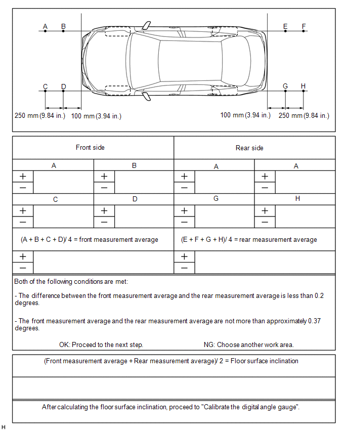
(7) Average the front measurement average and the rear measurement average, then round the answer to 1 decimal place (E.g. 0.0927 degrees is rounded to 0.1 degrees) to obtain the floor surface inclination value.
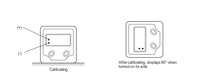
(8) Calibrate the digital angle gauge
Adjust the angle of the digital angle gauge until it reads the same value of the floor surface inclination, then press the "ZERO" switch to memorize the zero point (level with floor surface).
NOTICE:
Before pressing the "ZERO" switch, confirm that the digital angle gauge reading is positive if the floor angle inclination is positive, and negative if the floor angle inclination is negative.
(c) Prepare the digital angle gauge
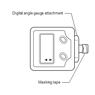
(1) Attach the digital angle gauge attachment to the digital angle gauge.
SST: 09989-00020
(2) Attach masking tape to the digital angle gauge attachment.
(d) Remove all luggage from the vehicle.
(e) Adjust the tire inflation pressure to the specified pressure.
Click here
(f) Check the height of the vehicle.
Click here
SENSOR HEIGHT AND ALIGNMENT INSPECTION (PROCEDURE 3)
HINT:
Check if the installation angle of each ultrasonic sensor is appropriate.
(a) Preparation
(1) Visually check that the bumper, grill and ultrasonic sensors are installed properly and are not damaged.
NOTICE:
If the bumper, grill or any ultrasonic sensor is not installed correctly, the calibration may not be able to be completed.
(2) Check the tire pressures and adjust them if necessary.
Click here
NOTICE:
(b) Sensor height and alignment inspection
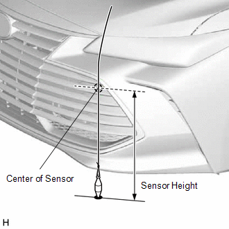
(c) Measure the installation height of the sensors.
for Bar Type Radiator Grille:
Standard Height (Front Bumper):|
Sensor Location | Sensor Height |
|---|---|
|
Front Center Ultrasonic Sensor |
507.2 to 565.1 mm (20.0 to 22.2 in.) |
|
Front Corner Ultrasonic Sensor |
513.9 to 572.0 mm (20.2 to 22.5 in.) |
|
Sensor Location | Sensor Height |
|---|---|
|
Rear Center Ultrasonic Sensor |
511.3 to 569.2 mm (20.1 to 22.4 in.) |
|
Rear Corner Ultrasonic Sensor |
514.7 to 572.7 mm (20.3 to 22.5 in.) |
for Mesh Type Radiator Grille:
Standard Height (Front Bumper):|
Sensor Location | Sensor Height |
|---|---|
|
Front Center Ultrasonic Sensor |
479.6 to 623.0 mm (18.9 to 24.5 in.) |
|
Front Corner Ultrasonic Sensor |
376.7 to 519.1 mm (14.8 to 20.4 in.) |
|
Sensor Location | Sensor Height |
|---|---|
|
Rear Center Ultrasonic Sensor |
479.6 to 623.0 mm (18.9 to 24.5 in.) |
|
Rear Corner Ultrasonic Sensor |
376.7 to 519.1 mm (14.8 to 20.4 in.) |
NOTICE:
If the installation height of a sensor is not as specified, it may not be possible to measure the sensor angles correctly. If so, unload the vehicle and measure the installation height of the sensors again.
HINT:
Use the center of the sensor as the measuring point.
(d) Using the digital angle gauge, measure the angles of each sensor. Write down the measured values.
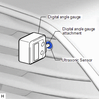
(1) Measure the angle of the front sensors as shown in the illustration.
NOTICE:
Ensure that the digital angle gauge is flush with the face of the sensor.
(2) Measure the angle of the rear sensors.
NOTICE:
Ensure that the digital angle gauge is flush with the face of the sensor.
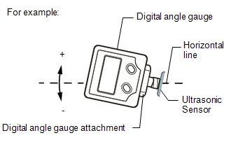
(3) Confirm that the angles of the sensors are as specified.
NOTICE:
The sensor angle is the measured sensor angle subtracted from 90°.
HINT:
Standard Angle (Front Bumper):
|
Sensor Location | Installation Angle |
|---|---|
|
Front Center Ultrasonic Sensor |
-0.80 to 6.18° |
|
Front Corner Ultrasonic Sensor |
-0.80 to 6.18° |
Standard Angle (Rear Bumper):
|
Sensor Location | Installation Angle |
|---|---|
|
Rear Center Ultrasonic Sensor |
-0.78 to 6.20° |
|
Rear Corner Ultrasonic Sensor |
2.42 to 9.40° |
(4) If the angle or height of the sensors is not as specified, confirm that the installation is correct and then perform troubleshooting again.
REGISTRATION (PROCEDURE 4)
(a) Preparation
(1) Confirm that the following DTCs are not output.
|
System | Proceed to |
|---|---|
|
Intuitive Parking Assist System |
|
|
Intelligent Clearance Sonar System |
|
NOTICE:
If DTC C1AEC, C1AED, C1AF0, C1AF3, C1AF4, C1AEA or C168D are output at this point, it is not due to a malfunction. Proceed with the calibration.
(b) Connect the Techstream to the DLC3.
(c) Turn the engine switch on (IG).
(d) Turn the Techstream on.
(e) Enter the following menus: Body Electrical / Advanced Parking Guidance/ICS/Intuitive P/A / Utility.
Body Electrical > Advanced Parking Guidance/ICS/Intuitive P/A > Utility|
Tester Display |
|---|
| Intuitive P/A Detection/Steering Adjustment |
(f) According to the display on the Techstream, perform calibration.
HINT:
If "Battery or Steering Sensor" is selected, further calibration is not required. (Bumper type registration is not required.)
(g) Enter the bumper type using the Techstream.
|
Bumper Type | Value |
|---|---|
|
for Bar Type Radiator Grille |
1 |
| for Mesh Type Radiator Grille |
2 |
HINT:
If the clearance warning ECU assembly is replaced or removed and installed, it is necessary to perform bumper type registration.
(h) Using the Techstream, enter the measured sensor values.
NOTICE:
The sensor angle is the measured sensor angle subtracted from 90°.
HINT:
The digital angle gauge should indicate 90° when turned on its side.
(i) Disconnect the Techstream from the DLC3.
CUSTOMIZE PARAMETERS
CUSTOMIZE INTELLIGENT CLEARANCE SONAR SYSTEM
(a) Customizing with the Techstream.
NOTICE:
(1) Connect the Techstream to the DLC3.
(2) Turn the engine switch on (IG).
(3) Turn the Techstream on.
(4) Enter the following menus: Body Electrical / Advanced Parking Guidance/ICS/Intuitive P/A / Utility / Customize Setting.
(5) Select the setting by referring to the table below.
Warning|
Tester Display | Description |
Default | Setting |
ECU |
|---|---|---|---|---|
| Fr Corner Sensor Onset Range |
Sets the detection operation range for the front corner sensors. |
Long | 0:Short,1:Long |
Clearance warning ECU assembly |
|
Rr Corner Sensor Onset Range |
Sets the detection operation range for the rear corner sensors. |
Long | 0:Short,1:Long |
Clearance warning ECU assembly |
|
Fr Sensor Onset Range | Sets the detection operation range for the front center sensors. |
Wide | 0:Narrow,1:Wide |
Clearance warning ECU assembly |
|
Rr Sensor Onset Range | Sets the detection operation range for the rear center sensors. |
Wide | 0:Narrow,1:Wide |
Clearance warning ECU assembly |
|
Keep Sense Buzzer | Sets whether the buzzer stops sounding when the distance between the vehicle and a detected object does not change for 3 seconds. |
Avail | 0:Not Avail,1:Avail |
Clearance warning ECU assembly |
|
Fr & Rr Buzzer Volume |
Changes the buzzer volume setting. |
M2 | 001:L,010:M1,011:M2,100:M3,101:H |
Clearance warning ECU assembly |
|
Object Not Moving 3s Buzz Vol |
Sets the volume at which the buzzer sounds when the distance between the vehicle and a detected object does not change for 3 seconds. |
Keep | 00:Keep Vol,01:L,10:M1,11:M2 |
Clearance warning ECU assembly |
|
Leave Buzzer Volume | Sets the volume of the buzzer with respect to the distance between the vehicle and a detected object. |
L | 00:Keep Vol,01:L,10:M1,11:M2 |
Clearance warning ECU assembly |
|
Temporary Mute Reset Speed Adjust |
Sets the vehicle speed at which the temporary mute function resets. |
20 km/h | 00:System Link,01:15km/h,10:20km/h,11:30km/h |
Clearance warning ECU assembly |
|
Temporary Mute Function |
Sets the availability of the temporary mute function. |
ON | 0:OFF,1:ON |
Clearance warning ECU assembly |
|
Tester Display | Description |
Default | Setting |
ECU |
|---|---|---|---|---|
| Sensor Condition N |
Makes the front sensors available when shift lever is in N. |
Avail | 0:Not Avail,1:Avail |
Clearance warning ECU assembly |
|
Tester Display | Description |
Default | Setting |
ECU |
|---|---|---|---|---|
| Approach Display OFF |
Sets whether the display turns off after an obstacle is no longer detected. |
Avail | 0:Not Avail,1:Avail |
Clearance warning ECU assembly |
|
Display Mode | The display mode setting (when the intuitive parking assist system is normal). |
All | 01:All,11:Undisp |
Clearance warning ECU assembly |
|
Tester Display | Description |
Default | Setting |
ECU |
|---|---|---|---|---|
| ICS Function |
Intelligent clearance sonar system |
ON | 0:ON,1:OFF |
Clearance warning ECU assembly |
|
ICS SW Status Memory | Intelligent clearance sonar system main switch memory function |
Yes | 0:Yes,1:No |
Clearance warning ECU assembly |
|
ICS Stop Distance | Intelligent clearance sonar system target stopping distance |
Long | 0:Short,1:Long |
Clearance warning ECU assembly |
|
RCTAB Function | Setting of the rear cross traffic auto brake function |
ON | 0:ON,1:OFF |
Clearance warning ECU assembly |
|
RCTAB Operation Timing Setting |
Setting of the activation timing of the rear cross traffic auto brake function |
Standard | 0:Late,1:Standard |
Clearance warning ECU assembly |
|
RCTAB Sensitivity | Setting of the sensitivity of the rear cross traffic auto brake function |
Standard | 0:Standard,1:Low |
Clearance warning ECU assembly |
DATA LIST / ACTIVE TEST
DATA LIST
NOTICE:
In the table below, the values listed under "Normal Condition" are reference values. Do not depend solely on these reference values when deciding whether a part is faulty or not.
HINT:
Using the Techstream to read the Data List allows the values or states of switches, sensors, actuators and other items to be read without removing any parts. This non-intrusive inspection can be very useful because intermittent conditions or signals may be discovered before parts or wiring is disturbed. Reading the Data List information early in troubleshooting is one way to save diagnostic time.
(a) Connect the Techstream to the DLC3.
(b) Turn the engine switch on (IG).
(c) Turn the Techstream on.
(d) Enter the following menus: Body Electrical / Advanced Parking Guidance/ICS/Intuitive P/A / Data List.
(e) Read the Data List according to the display on the Techstream.
Body Electrical > Advanced Parking Guidance/ICS/Intuitive P/A > Data List|
Tester Display | Measurement Item |
Range | Normal Condition |
Diagnostic Note |
|---|---|---|---|---|
|
ICS SW Status | Intelligent clearance sonar system switch assembly (Multi-information switch) |
OFF or ON | OFF: Intelligent clearance sonar system off ON: Intelligent clearance sonar system on |
- |
| Fr Sensor Onset Range |
Detection operation range (for front center sensors) |
Narrow or Wide | Narrow: 600 mm (23.6 in.) Wide: 1000 mm (39.4 in.) |
Customized value displayed |
|
Rr Sensor Onset Range | Detection operation range (for rear center sensors) |
Narrow or Wide | Narrow: 600 mm (23.6 in.) Wide: 1500 mm (59.1 in.) |
Customized value displayed |
|
Keep Sense Buzzer | Keep sense buzzer operation |
Not Avail or Avail | Not Avail: Buzzer stops Avail: Buzzer sounds continuously |
Customized value displayed |
|
Fr & Rr Buzzer Volume |
Buzzer volume setting | L, M or H |
L: Low volume M: Medium volume H: High volume |
Customized value displayed |
|
Sensor Condition N | Front sensor operation |
Not Avail or Avail | Not Avail: Front sensors not available Avail: Front sensors available |
Customized value displayed |
|
Approach Display OFF | Whether the display turns off after an obstacle is no longer detected. |
Not Avail or Avail | Not Avail: Not displayed Avail: Displayed | Customized value displayed |
|
BSM Radar Communication Invalid History |
BSM radar communication invalid history |
Yes or No | Yes: History stored No: History not stored |
- |
| Target 1 Distance (FLC Sensor) |
Distance between ultrasonic sensor and target object |
Unknown, Not Detected or 0.00 to 7.65 m (0.00 to 25.09 ft.) |
Unknown: Detection conditions not met Not Detected: No objects detected 0.00 to 7.65 m (0.00 to 25.09 ft.): Detected distance |
- |
| Target 1 Distance (FRC Sensor) |
Distance between ultrasonic sensor and target object |
Unknown, Not Detected or 0.00 to 7.65 m (0.00 to 25.09 ft.) |
Unknown: Detection conditions not met Not Detected: No objects detected 0.00 to 7.65 m (0.00 to 25.09 ft.): Detected distance |
- |
| Target 1 Distance (RLC Sensor) |
Distance between ultrasonic sensor and target object |
Unknown, Not Detected or 0.00 to 7.65 m (0.00 to 25.09 ft.) |
Unknown: Detection conditions not met Not Detected: No objects detected 0.00 to 7.65 m (0.00 to 25.09 ft.): Detected distance |
- |
| Target 1 Distance (RRC Sensor) |
Distance between ultrasonic sensor and target object |
Unknown, Not Detected or 0.00 to 7.65 m (0.00 to 25.09 ft.) |
Unknown: Detection conditions not met Not Detected: No objects detected 0.00 to 7.65 m (0.00 to 25.09 ft.): Detected distance |
- |
| Target 1 Distance (FL Sensor) |
Distance between ultrasonic sensor and target object |
Unknown, Not Detected or 0.00 to 5.10 m |
Unknown: Detection conditions not met Not Detected: No objects detected 0.00 to 5.10 m (0.00 to 16.73 ft.): Detected distance |
- |
| Target 1 Distance (FR Sensor) |
Distance between ultrasonic sensor and target object |
Unknown, Not Detected or 0.00 to 5.10 m (0.00 to 16.73 ft.) |
Unknown: Detection conditions not met Not Detected: No objects detected 0.00 to 5.10 m (0.00 to 16.73 ft.): Detected distance |
- |
| Target 1 Distance (RL Sensor) |
Distance between ultrasonic sensor and target object |
Unknown, Not Detected or 0.00 to 5.10 m (0.00 to 16.73 ft.) |
Unknown: Detection conditions not met Not Detected: No objects detected 0.00 to 5.10 m (0.00 to 16.73 ft.): Detected distance |
- |
| Target 1 Distance (RR Sensor) |
Distance between ultrasonic sensor and target object |
Unknown, Not Detected or 0.00 to 5.10 m (0.00 to 16.73 ft.) |
Unknown: Detection conditions not met Not Detected: No objects detected 0.00 to 5.10 m (0.00 to 16.73 ft.): Detected distance |
- |
| Target 2 Distance (FLC Sensor) |
Distance between ultrasonic sensor and target object |
Unknown, Not Detected or 0.00 to 7.65 m |
Unknown: Detection conditions not met Not Detected: No objects detected 0.00 to 7.65 m (0.00 to 25.09 ft.): Detected distance |
- |
| Target 2 Distance (FRC Sensor) |
Distance between ultrasonic sensor and target object |
Unknown, Not Detected or 0.00 to 7.65 m (0.00 to 25.09 ft.) |
Unknown: Detection conditions not met Not Detected: No objects detected 0.00 to 7.65 m (0.00 to 25.09 ft.): Detected distance |
- |
| Target 2 Distance (RLC Sensor) |
Distance between ultrasonic sensor and target object |
Unknown, Not Detected or 0.00 to 7.65 m (0.00 to 25.09 ft.) |
Unknown: Detection conditions not met Not Detected: No objects detected 0.00 to 7.65 m (0.00 to 25.09 ft.): Detected distance |
- |
| Target 2 Distance (RRC Sensor) |
Distance between ultrasonic sensor and target object |
Unknown, Not Detected or 0.00 to 7.65 m (0.00 to 25.09 ft.) |
Unknown: Detection conditions not met Not Detected: No objects detected 0.00 to 7.65 m (0.00 to 25.09 ft.): Detected distance |
- |
| Target 2 Distance (FL Sensor) |
Distance between ultrasonic sensor and target object |
Unknown, Not Detected or 0.00 to 5.10 m (0.00 to 16.73 ft.) |
Unknown: Detection conditions not met Not Detected: No objects detected 0.00 to 5.10 m (0.00 to 16.73 ft.): Detected distance |
- |
| Target 2 Distance (FR Sensor) |
Distance between ultrasonic sensor and target object |
Unknown, Not Detected or 0.00 to 5.10 m (0.00 to 16.73 ft.) |
Unknown: Detection conditions not met Not Detected: No objects detected 0.00 to 5.10 m (0.00 to 16.73 ft.): Detected distance |
- |
| Target 2 Distance (RL Sensor) |
Distance between ultrasonic sensor and target object |
Unknown, Not Detected or 0.00 to 5.10 m (0.00 to 16.73 ft.) |
Unknown: Detection conditions not met Not Detected: No objects detected 0.00 to 5.10 m (0.00 to 16.73 ft.): Detected distance |
- |
| Target 2 Distance (RR Sensor) |
Distance between ultrasonic sensor and target object |
Unknown, Not Detected or 0.00 to 5.10 m (0.00 to 16.73 ft.) |
Unknown: Detection conditions not met Not Detected: No objects detected 0.00 to 5.10 m (0.00 to 16.73 ft.): Detected distance |
- |
| ICS Function |
Current setting of intelligent clearance sonar system |
ON or OFF | ON: Intelligent clearance sonar system enabled OFF: Intelligent clearance sonar system disabled |
Customized value displayed |
|
ICS System | Existence of intelligent clearance sonar system |
Without or With | Without: w/o Intelligent clearance sonar system With: w/ Intelligent clearance sonar system |
- |
| ICS Stop Distance |
Target stop distance | Short or Long |
Short: Near Long: Far |
Customized value displayed |
|
ICS SW Status Memory | Setting that determines if the on/off operation state when the engine switch is turned off is resumed when the engine switch is turned on |
Yes or No | Yes: Previous on/off operation state is resumed No: System operates when the engine switch is turned on |
Customized value displayed |
|
Bumper Type | Registered bumper type |
Unfixed or 1 to 127 | 1: Bumper for bar type radiator grille 2: Bumper for mesh type radiator grille 3 to 127: Unknown Unfixed: Unknown | - |
|
RCTAB Function | Setting of the rear traffic auto brake function |
ON/OFF | ON: Rear traffic auto brake function ON OFF: Rear traffic auto brake function OFF |
- |
| RCTAB Operation Timing Setting |
Setting of the activation timing of the rear traffic auto brake function |
Standard or Late | Late: Late timing Standard: Standard timing |
- |
| RCTAB Sensitivity |
Setting of the sensitivity of the rear traffic auto brake function |
Low or Standard | Standard: Standard sensitivity Low: Low sensitivity |
- |
| # Codes |
Number of stored DTCs | min.: 0, max.: 255 |
Number of DTCs will be displayed |
- |
ACTIVE TEST
HINT:
Using the Techstream to perform Active Tests allows relays, VSVs, actuators and other items to be operated without removing any parts. This non-intrusive functional inspection can be very useful because intermittent operation may be discovered before parts or wiring is disturbed. Performing Active Tests early in troubleshooting is one way to save diagnostic time. Data List information can be displayed while performing Active Tests.
(a) Connect the Techstream to the DLC3.
(b) Turn the engine switch on (IG).
(c) Turn the Techstream on.
(d) Enter the following menus: Chassis / ABS/VSC/TRAC / Active Test.
(e) According to the display on the Techstream, perform the Active Test.
Chassis > ABS/VSC/TRAC > Active Test|
Tester Display | Measurement Item |
Control Range | Diagnostic Note |
|---|---|---|---|
|
Stop Light Relay | Stop lights |
ON / OFF | Test possible at vehicle speed of 0 km/h (0 mph) |
(f) Enter the following menus: Body Electrical / Combination Meter / Active Test.
(g) According to the display on the Techstream, perform the Active Test.
Body Electrical > Combination Meter > Active Test|
Tester Display | Measurement Item |
Control Range | Diagnostic Note |
|---|---|---|---|
|
ICS OFF Indicator | ICS OFF indicator light |
ON / OFF | - |
(h) Enter the following menus: Body Electrical / Advanced Parking Guidance/ICS/Intuitive P/A / Active Test.
(i) According to the display on the Techstream, perform the Active Test.
Body Electrical > Advanced Parking Guidance/ICS/Intuitive P/A > Active Test|
Tester Display | Measurement Item |
Control Range | Diagnostic Note |
|---|---|---|---|
|
Rear Buzzer | No. 1 clearance warning buzzer |
Stop or Operate | Confirm that the vehicle is stopped and the engine switch is on (IG) |
|
Front/Rear Buzzer | No. 2 clearance warning buzzer |
Stop or Operate | Confirm that the vehicle is stopped and the engine switch is on (IG) |
DIAGNOSIS SYSTEM
DESCRIPTION
(a) Intelligent clearance sonar system data and Diagnostic Trouble Codes (DTCs) can be read from the Data Link Connector 3 (DLC3) of the vehicle. When the system seems to be malfunctioning, use the Techstream to check for malfunctions and to repair them.
CHECK DLC3
(a) Check the DLC3.
Click here 
DESCRIPTION
(a) When the intelligent clearance sonar system is unavailable either temporarily or due to a malfunction, a warning message is displayed on the multi-information display.
Multi-information Display Warning Message|
Warning Message | Proceed to |
|---|---|
|
"ICS Malfunction Visit Your Dealer" |
|
|
"ICS Unavailable" |
DIAGNOSTIC TROUBLE CODE CHART
Intelligent Clearance Sonar System|
DTC No. | Detection Item |
Link |
|---|---|---|
| C1611 |
ECU Malfunction |
|
|
C1625 | Open or Short in Steering Angle Sensor +B |
|
|
C1626 | Steering Angle Sensor Failure |
|
|
C1647 | G Sensor Failure |
|
|
C164B | Communication Error From Clearance Sonar ECU to VSC |
|
|
C164D | Wheel Speed Sensor Malfunction |
|
|
C164E | Stop Switch Circuit Malfunction |
|
|
C164F | Brake Hydraulic Pressure Malfunction |
|
|
C1652 | Outside Air Temperature Sensor |
|
|
C168D | Vehicle Information Unmatched |
|
|
C1A40 | ENG / EHV Device |
|
|
C1A4B | Stop Light Relay Circuit |
|
|
C1A50 | Brake System |
|
|
C1AEA | Steering Angle Midpoint Initial Setting Incomplete |
|
|
C1AF0 | ICS Detection Area Adjustment Incomplete |
|
|
C1AF3 | Fr Sensor Initialization Incomplete |
|
|
C1AF4 | Rr Sensor Initialization Incomplete |
|
|
C1AF7 | RCTB Sensor |
|
|
C1AF9 | Blind Spot Monitor Beam Axis Inspection Incomplete |
|
|
C1AFA | Blind Spot Monitor Beam Axis Misalignment |
|
|
U0073 | Control Module Communication Bus "A" Off |
|
|
U0100 | Lost Communication with ECM / PCM "A" |
|
|
U0124 | Lost Communication with Lateral Acceleration Sensor Module |
|
|
U0126 | Lost Communication with Steering Angle Sensor Module |
|
|
U0129 | Lost Communication with Brake System Control Module |
|
|
U0140 | Lost Communication with Body Control Module |
|
|
U0155 | Lost Communication With Instrument Panel Cluster (IPC) Control Module |
|
|
U0164 | Lost Communication with HVAC Control Module |
|
|
U0232 | Lost Communication with Blind Spot Monitor Slave Module |
|
|
U0233 | Lost Communication with Blind Spot Monitor Master Module |
|
|
U1000 | CAN Communication Failure (Message Registry) |
|
DTC CHECK / CLEAR
CHECK DTC
(a) Connect the Techstream to the DLC3.
(b) Turn the engine switch on (IG).
(c) Turn the intelligent clearance sonar system on.
(d) Turn the Techstream on.
(e) Enter the following menus: Body Electrical / Advanced Parking Guidance/ICS/Intuitive P/A / Trouble Codes.
(f) Check for DTCs.
Click here 
CLEAR DTC
(a) Connect the Techstream to the DLC3.
(b) Turn the engine switch on (IG).
(c) Turn the intelligent clearance sonar system on.
(d) Turn the Techstream on.
(e) Enter the following menus: Body Electrical / Advanced Parking Guidance/ICS/Intuitive P/A / Trouble Codes.
(f) Clear the DTCs.
Body Electrical > Advanced Parking Guidance/ICS/Intuitive P/A > Clear DTCsFAIL-SAFE CHART
FAIL-SAFE FUNCTION
(a) If a malfunction is detected in the intelligent clearance sonar system, the warning message "ICS System Malfunction Visit Your Dealer" or "ICS Unavailable" is displayed on the multi-information display, the ICS OFF indicator blinks and the intelligent clearance sonar system control is prohibited as necessary.
(b) If the clearance warning ECU assembly judges that there is foreign matter on an ultrasonic sensor or detection of objects is not possible in severe weather such as snow, the warning message "ICS Unavailable" is displayed, the ICS OFF indicator blinks and control is cancelled. The warning message "ICS Unavailable" is temporarily displayed and turns off. The ICS OFF indicator blinks to inform the driver of the malfunction. When detection of an obstacle is possible, the ICS OFF indicator turns off and the intelligent clearance sonar system control returns to normal.
CAUTION / NOTICE / HINT
HINT:
PROCEDURE
|
1. | VEHICLE BROUGHT TO WORKSHOP |
|
| 2. |
CUSTOMER PROBLEM ANALYSIS |
|
| 3. |
INSPECT BATTERY VOLTAGE |
(a) Measure the battery voltage.
Standard Voltage:
11 to 14 V
If the voltage is below 11 V, replace or recharge the battery before proceeding to the next step.
|
| 4. |
CHECK CAN COMMUNICATION SYSTEM* |
(a) Use the Techstream to check if the CAN communication system is functioning normally.
Click here 
|
Result | Proceed to |
|---|---|
|
CAN communication system DTCs are not output |
A |
| CAN communication system DTCs are output |
B |
| B |
 | GO TO CAN COMMUNICATION SYSTEM |
|
| 5. |
PROBLEM SYMPTOM CONFIRMATION |
|
| 6. |
CHECK DTC* |
(a) Check for DTCs.
Body Electrical > Advanced Parking Guidance/ICS/Intuitive P/A > Trouble Codes|
Result | Proceed to |
|---|---|
|
DTCs are output | A |
|
DTCs are not output (Problem symptom does not occur) |
B |
| DTCs are not output (Problem symptom occurs) |
C |
| B |
| GO TO STEP 8 |
| C |
| GO TO STEP 9 |
|
| 7. |
DIAGNOSTIC TROUBLE CODE CHART (INTELLIGENT CLEARANCE SONAR SYSTEM) |
(a) Refer to Diagnostic Trouble Code Chart.
Click here
NOTICE:
The clearance warning ECU assembly outputs DTCs for the following system. When DTCs other than those in Diagnostic Trouble Code Chart for the intelligent clearance sonar system are output, refer to Diagnostic Trouble Code Chart for the relevant systems.
|
System | Proceed to |
|---|---|
|
Intuitive Parking Assist System |
|
| NEXT | | GO TO STEP 11 |
| 8. |
SYMPTOM SIMULATION |
(a) Refer to Symptom Simulation.
Click here
|
| 9. |
PROBLEM SYMPTOMS TABLE |
(a) Refer to Problem Symptoms Table.
Click here
|
Result | Proceed to |
|---|---|
|
Fault is not listed in Problem Symptoms Table |
A |
| Fault is listed in Problem Symptoms Table |
B |
| B |
| GO TO STEP 11 |
|
| 10. |
OVERALL ANALYSIS AND TROUBLESHOOTING |
(a) Operation Check
Click here
(b) Terminals of ECU
Click here
(c) Data List / Active Test
Click here
|
| 11. |
CIRCUIT INSPECTION |
|
| 12. |
IDENTIFICATION OF PROBLEM |
|
| 13. |
REPAIR OR REPLACE |
|
| 14. |
CONFIRMATION TEST |
| NEXT | | END |
OPERATION CHECK
ICS OFF INDICATOR LIGHT OPERATION CHECK
(a) Turn the engine switch on (IG).
(b) Turn the intelligent clearance sonar system off and confirm that the ICS OFF indicator in the combination meter illuminates.
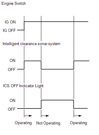
HINT:
If the intelligent clearance sonar system is not set to off in the customize settings, the intelligent clearance sonar system will operate when the engine switch is turned on (IG).
DETECTION AREA
(a) Intelligent clearance sonar system detection distance
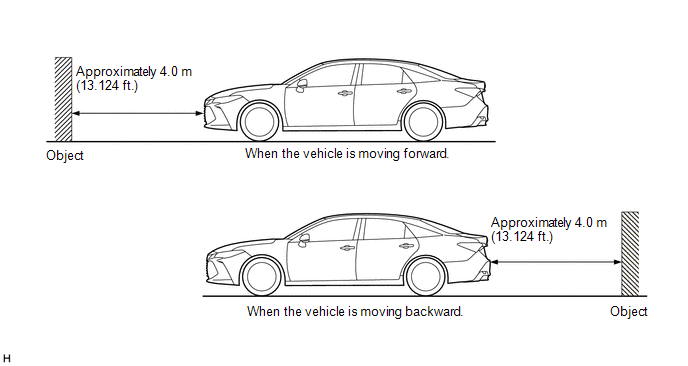
HINT:
The detection range shown in the illustration is for when detecting an object that is 2.0 m (6.562 ft.) wide, 1.0 m (3.281 ft.) tall and is perpendicular to the ground.
NOTICE:
Even if the intelligent clearance sonar system detects an object, the system may not operate depending on the vehicle conditions.
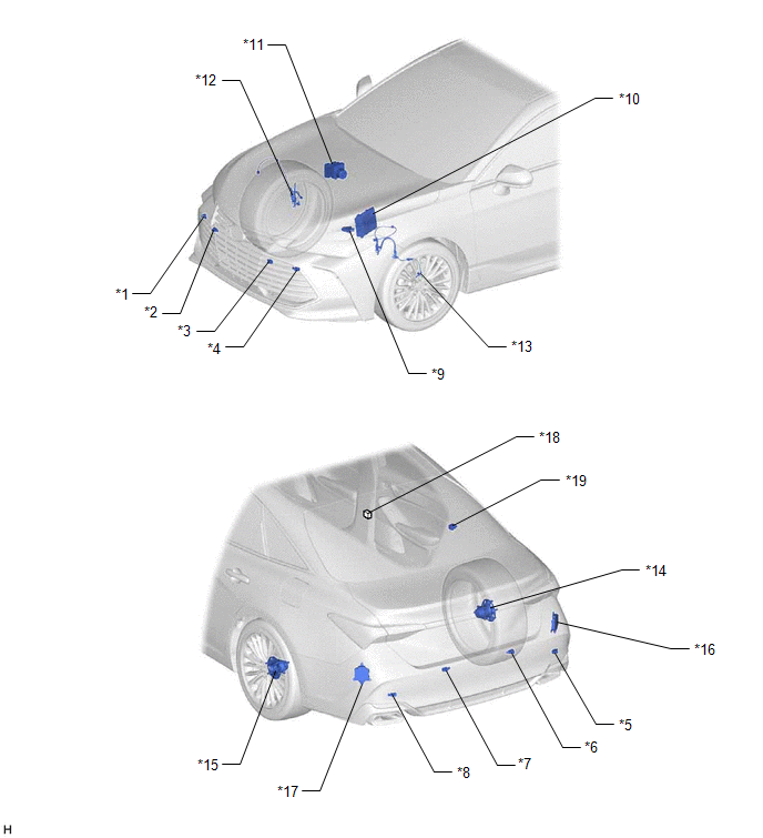
PARTS LOCATION
ILLUSTRATION
|
*1 | FRONT CORNER ULTRASONIC SENSOR RH |
*2 | FRONT CENTER ULTRASONIC SENSOR RH |
|
*3 | FRONT CENTER ULTRASONIC SENSOR LH |
*4 | FRONT CORNER ULTRASONIC SENSOR LH |
|
*5 | REAR CORNER ULTRASONIC SENSOR RH |
*6 | REAR CENTER ULTRASONIC SENSOR RH |
|
*7 | REAR CENTER ULTRASONIC SENSOR LH |
*8 | REAR CORNER ULTRASONIC SENSOR LH |
|
*9 | PARK/NEUTRAL POSITION SWITCH ASSEMBLY |
*10 | ECM |
|
*11 | BRAKE ACTUATOR ASSEMBLY - SKID CONTROL ECU | *12 |
FRONT SPEED SENSOR RH |
|
*13 | FRONT SPEED SENSOR LH |
*14 | REAR AXLE HUB AND BEARING ASSEMBLY RH - REAR SPEED SENSOR RH |
|
*15 | REAR AXLE HUB AND BEARING ASSEMBLY LH - REAR SPEED SENSOR LH |
*16 | BLIND SPOT MONITOR SENSOR RH |
|
*17 | BLIND SPOT MONITOR SENSOR LH |
*18 | NO. 26 JUNCTION CONNECTOR (w/ Blind Spot Monitor System) |
|
*19 | NO. 2 CLEARANCE WARNING BUZZER |
- | - |
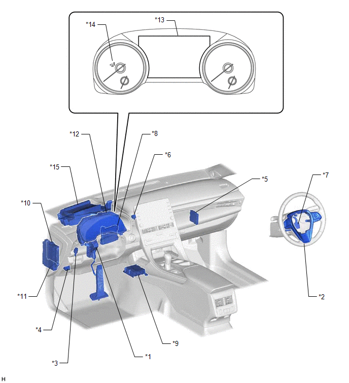
ILLUSTRATION
|
*1 | ACCELERATOR PEDAL SENSOR |
*2 | STEERING PAD SWITCH ASSEMBLY |
|
*3 | STOP LIGHT SWITCH ASSEMBLY |
*4 | DLC3 |
|
*5 | CLEARANCE WARNING ECU ASSEMBLY |
*6 | NO. 1 CLEARANCE WARNING BUZZER |
|
*7 | STEERING SENSOR |
*8 | AIR CONDITIONING AMPLIFIER ASSEMBLY |
|
*9 | AIRBAG ECU ASSEMBLY - YAW RATE AND ACCELERATION SENSOR |
*10 | MAIN BODY ECU (MULTIPLEX NETWORK BODY ECU) |
|
*11 | INSTRUMENT PANEL JUNCTION BLOCK ASSEMBLY - ECU-DCC NO. 1 FUSE - ECU-IG1 NO.4 FUSE - ECU-IG1 NO. 2 FUSE |
*12 | COMBINATION METER ASSEMBLY |
|
*13 | MULTI-INFORMATION DISPLAY |
*14 | ICS OFF INDICATOR |
|
*15 | HEADUP DISPLAY (METER MIRROR SUB-ASSEMBLY) (w/ Headup Display System) |
- | - |
PRECAUTION
PRECAUTION FOR DISCONNECTING CABLE FROM NEGATIVE BATTERY TERMINAL
NOTICE:
When disconnecting the cable from the negative (-) battery terminal, initialize the following systems after the cable is reconnected.
|
System Name | See Procedure |
|---|---|
|
Lane Departure Alert System (w/ Steering Control) |
|
|
Intelligent Clearance Sonar System | |
|
Parking Assist Monitor System | |
|
Panoramic View Monitor System | |
|
Pre-collision System | |
|
Lighting System (for Gasoline Model with Cornering Light) |
PRECAUTION FOR SERVICING VEHICLE
(a) After ECUs or parts are removed and installed, or replaced during inspection or servicing the vehicle, it is necessary to perform certain procedures (adjustment, calibration, initialization or registration).
Click here

PRECAUTION FOR TROUBLESHOOTING
(a) When a terminal contact is loose or damaged or a part is improperly installed, the system may only temporarily return to normal if the part is removed and installed without thorough diagnosis and repair.
(b) In order to assist with diagnosis, check and make a note of related information such as DTCs and Freeze Frame Data before disconnecting any connectors or removing and installing parts.
(c) Since the system may be influenced by malfunctions in systems other than the intelligent clearance sonar system, be sure to check for any past and present DTCs in other systems.
HANDLING PRECAUTIONS FOR ECU OR SENSOR
(a) Unless specified by the inspection procedure, make sure that the engine switch is off when removing or installing each ECU or ultrasonic sensor.
(b) After removing and installing each ECU or ultrasonic sensor and all parts have been installed, check and ensure that no DTCs are output.
HANDLING PRECAUTIONS FOR INTELLIGENT CLEARANCE SONAR SYSTEM
(a) Make sure to observe the following points when using the intelligent clearance sonar system.
(1) Do not rely solely upon the intelligent clearance sonar system. Relying solely upon the intelligent clearance sonar system may lead to an unexpected accident.
(2) For the intelligent clearance sonar system to operate correctly, make sure to observe the following points for the ultrasonic sensors. If not, the ultrasonic sensors may not operate correctly, resulting a serious injury.
(3) Do not modify the suspension, as changes to the height or incline of the vehicle may prevent the ultrasonic sensors from correctly detecting obstacles. This may cause the system to fail to operate or to operate incorrectly.
(4) If the area around an ultrasonic sensor is subjected to an impact, equipment may not operate properly due to an ultrasonic sensor malfunction.
(5) When washing the vehicle with a high-pressure washer, do not spray water on the ultrasonic sensors or surrounding areas. High-pressure water can damage the ultrasonic sensors.
(6) When using steam to wash the vehicle, do not apply steam too close to the ultrasonic sensors. They may not function properly if subjected to steam.
PRECAUTIONS FOR INTELLIGENT CLEARANCE SONAR FUNCTION
(a) In the following situations, the intelligent clearance sonar system may not operate correctly.
(1) Environmental influence
(2) Influence from the weather
(3) Influence from other ultrasonic waves
(4) Changes in the vehicle
(b) The sensors cannot detect the following objects:
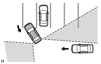
PRECAUTIONS FOR REAR CROSS TRAFFIC AUTO BRAKE FUNCTION
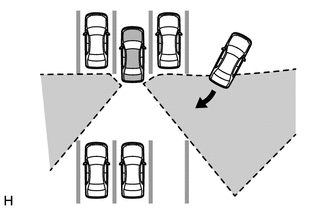
(a) The rear cross traffic auto brake function does not detect the following objects and vehicles:
(1) Stationary objects.
(2) Vehicles moving away from this vehicle
(3) Moving objects other than passenger vehicles such as pedestrians, motorcycles or bicycles
(4) Objects extremely close to the blind spot monitor sensors
(5) The speed of a vehicle approaching the right or left at the rear of the vehicle is less than 8 km/h (5 mph).
(6) The speed of a vehicle approaching the right or left at the rear of the vehicle is more than 24 km/h (15 mph).
(b) The rear cross traffic auto brake function may not be able to detect objects in the following situations:
(1) When the vehicle is parked in a very hot or cold environment.
(2) When foreign matter such as snow, ice or mud is attached to the rear bumper.
(3) During heavy rain or when water is splashing on the vehicle.
(4) When an approaching vehicle is blocked from a blind spot monitor sensor by an adjacent vehicle.
(5) When the vehicle is significantly tilted.
(6) When the vehicle is being towed.
(7) When the vehicle is equipped with lowered suspension or tires with a diameter different to that of the original.
(8) When the height of the vehicle has drastically changed (the nose is tilted up or down).
(9) When electronic components such as a backlit license plate, fog lights, a fender pole, wireless antenna or stickers are installed near the sensors.
(10) When a blind spot monitor sensor is misaligned.
(11) When several vehicles are approaching with little space between them.
(12) When a vehicle is approaching at high speed.
(c) The rear cross traffic auto brake function may not detect
(1) When a vehicle is approaching from behind.
(2) When the vehicle is parked at a shallow angle.
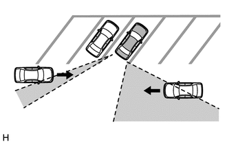
(3) When either of the blind spot monitor sensors is blocked such as by an adjacent vehicle.
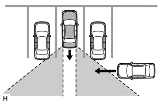
(4) When the vehicle is parked on a steep hill with varying gradients.
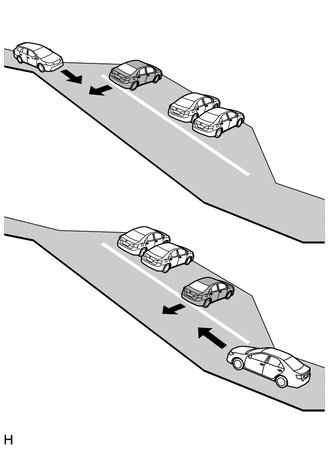
(5) When a vehicle turns in close proximity to the vehicle
PROBLEM SYMPTOMS TABLE
HINT:
|
Symptom | Suspected Area |
Link |
|---|---|---|
|
System does not operate at all |
Intuitive parking assist system |
|
|
CAN communication system |
| |
|
Clearance warning ECU assembly |
| |
|
Steering pad switch assembly |
| |
|
Blind spot monitor system |
|
|
Symptom | Suspected Area |
Link |
|---|---|---|
|
Detection function operates when the operating conditions are not met |
EFI system |
|
|
Clearance warning ECU assembly |
| |
|
Detection function operates when vehicle is not within the required speed range (speedometer not malfunctioning) |
CAN communication system |
|
|
Skid control ECU |
| |
|
Clearance warning ECU assembly |
|
|
Symptom | Suspected Area |
Link |
|---|---|---|
|
Intelligent clearance sonar system is normal but buzzer operation is intermittent |
Check that the temporary mute function is not operating |
- |
| Proceed to "No. 1 Clearance Warning Buzzer Circuit" |
| |
|
Proceed to "No. 2 Clearance Warning Buzzer Circuit" |
| |
|
Clearance warning ECU assembly |
| |
|
Combination meter assembly |
|
|
Symptom | Suspected Area |
Link |
|---|---|---|
|
While the ICS system is operating, no ICS notifications are displayed on the multi-information display. |
CAN communication system |
|
|
Clearance warning ECU assembly |
| |
|
Combination meter assembly |
| |
|
While the ICS system is operating, no ICS notifications are displayed on the headup display.* |
CAN communication system |
|
|
Clearance warning ECU assembly |
| |
|
Meter mirror sub-assembly |
| |
|
"ICS Malfunction Visit Your Dealer" is displayed |
Combination meter assembly |
|
|
Clearance warning ECU assembly |
| |
|
"ICS Unavailable" is displayed |
Check that no foreign matter is attached to the ultrasonic sensors. |
- |
| Steering angle neutral point (Intelligent clearance sonar system registration) |
| |
|
CAN communication system |
| |
|
Combination meter assembly |
| |
|
Clearance warning ECU assembly |
| |
|
ICS does not operate when there is a possibility of a collision (Warning message "ICS Unavailable" not displayed) |
Check the installation of the ultrasonic sensors (front) |
|
|
Check the installation of the ultrasonic sensors (rear) |
| |
|
Adjust the installation of the ultrasonic sensors as necessary. |
| |
|
Ultrasonic sensors (front) |
| |
|
Ultrasonic sensors (rear) |
| |
|
Clearance warning ECU assembly |
| |
|
ICS control operates when there is no possibility of a collision |
Check the installation of the ultrasonic sensors (front) |
|
|
Check the installation of the ultrasonic sensors (rear) |
| |
|
Adjust the installation of the ultrasonic sensors as necessary. |
| |
|
Ultrasonic sensors (front) |
| |
|
Ultrasonic sensors (rear) |
| |
|
Clearance warning ECU assembly |
| |
|
ICS control cannot be turned off (ICS OFF indicator does not illuminate) |
Combination meter assembly (LED): Perform Active Test (Indicat. ICS OFF LCD) |
|
|
Steering pad switch assembly |
| |
|
Clearance warning ECU assembly |
| |
|
ICS OFF indicator blinks | If "Yes" is displayed for the Data List item "BSM Radar Communication Invalid History", the blind spot monitor system may be malfunctioning. |
|
|
Check that no foreign matter is attached to the ultrasonic sensors. |
- | |
| Steering angle neutral point (Intelligent clearance sonar system registration) |
|
SYSTEM DESCRIPTION
FUNCTION OF COMPONENTS
(a) The intelligent clearance sonar system consists of the following components:
|
Component | Function |
|---|---|
|
Clearance Warning ECU Assembly |
|
| Steering Pad Switch Assembly - Multi-information Switch |
Enables, disables or cuts off the operation of the intelligent clearance sonar system by transmitting the switch operation signal to the combination meter assembly. |
| ECM |
|
| Combination Meter Assembly - Multi-information Display - ICS OFF Indicator - Meter buzzer |
|
| Headup Display* - Meter Mirror Sub-assembly |
Displays the control status of the intelligent clearance sonar system based on the signals received from the clearance warning ECU assembly via CAN communication. |
| Stop Light Switch Assembly |
Detects if the brake pedal is depressed and outputs a signal to the skid control ECU. |
|
Skid Control ECU |
|
| Steering Sensor |
Sends the steering angle signal to the clearance warning ECU assembly via CAN communication. |
|
Airbag ECU Assembly
| Sends the yaw rate and acceleration sensor signal to the clearance warning ECU assembly via CAN communication. |
| Sends the wheel speed signals to the skid control ECU. |
|
Park/neutral Position Switch Assembly |
Sends the shift state signal to the ECM. |
|
Ultrasonic Sensor | Detects the distance between the vehicle and an obstacle. |
| Sounds upon receiving signals from the Clearance Warning ECU Assembly. |
|
Accelerator Pedal Sensor Assembly |
Sends the accelerator pedal opening angle signal to the ECM. |
|
Main Body ECU (Multiplex Network Body ECU) |
Sends the driver seat belt signal to the clearance warning ECU assembly. |
|
Air Conditioning Amplifier Assembly |
Sends the ambient temperature signal to the clearance warning ECU assembly. |
|
Blind Spot Monitor Sensor (LH/RH) | Sends blind spot monitor system status signals to the clearance warning ECU assembly via CAN communication. |
OPERATION CONDITIONS (Intelligent Clearance Sonar System)
(a) Driving torque restriction control
(1) Initiation Condition (When all of the following conditions are met, the driving torque restriction control is performed.)
(2) Cancellation Condition (When any of the following conditions are met, driving torque restriction control is cancelled.)
(b) Brake Control
(1) Initiation Condition (When all of the following conditions are met, brake control is performed.)
(2) Cancellation Condition (When any of the following conditions are met, driving torque restriction control is cancelled.)
(c) Others
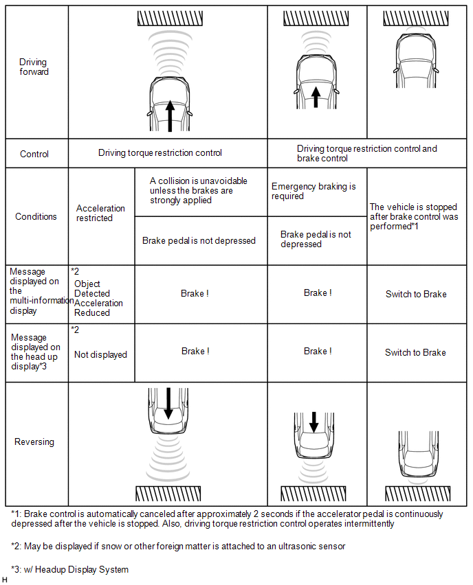
OPERATION CONDITIONS (Rear Cross Traffic Auto Brake Function)
(a) Driving torque restriction control
(1) Initiation Condition (When all of the following conditions are met, the driving torque restriction control is performed.)
(2) Cancellation Condition (When any of the following conditions are met, driving torque restriction control is cancelled.)
(b) Brake Control
(1) Initiation Condition (When all of the following conditions are met, brake control is performed.)
(2) Cancellation Condition (When any of the following conditions are met, driving torque restriction control is cancelled.)
(c) Others
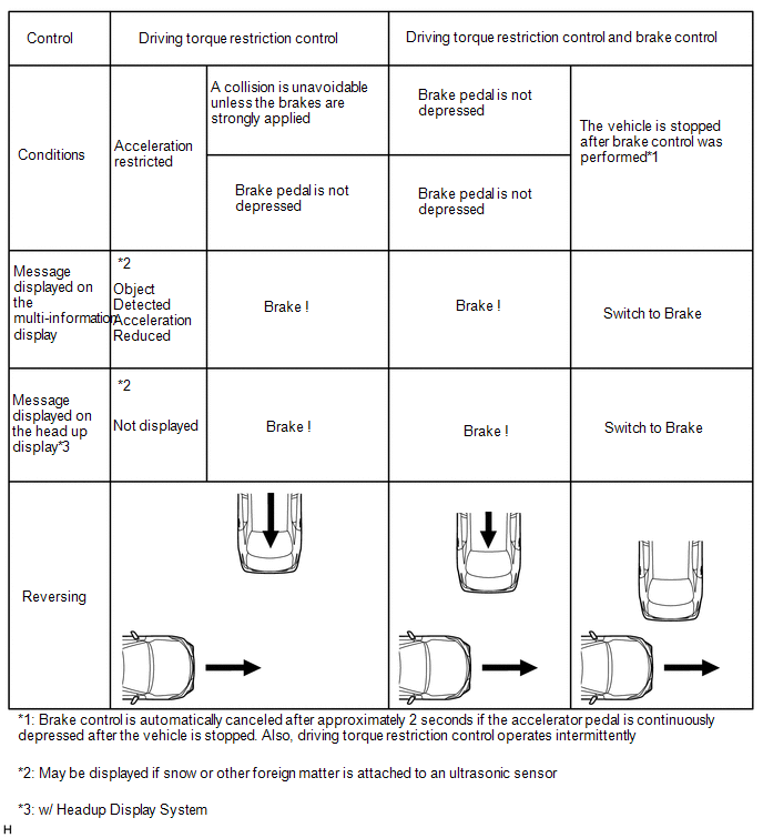
CASES OF UNNECESSARY INTELLIGENT CLEARANCE SONAR SYSTEM OPERATION
(a) In the following situations, the intelligent clearance sonar system may operate even when there is no possibility of a collision:
(1) Environmental influence
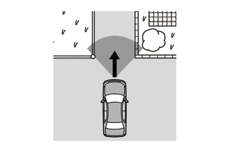
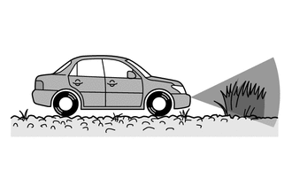
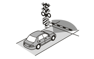
HINT:
Even if the intelligent clearance sonar system operates while on a railroad crossing, brake control will be automatically be canceled after approximately 2 seconds. Brake control can also be canceled by depressing the brake pedal. After brake control is canceled, depress the accelerator pedal to drive out of the railroad crossing.
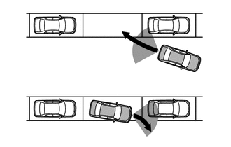
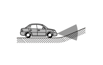
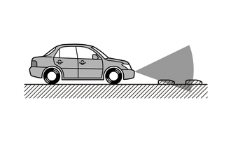
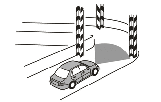
(2) Influence from the weather
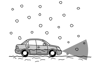
(3) Influence from other ultrasonic waves
(4) Changes in the vehicle.
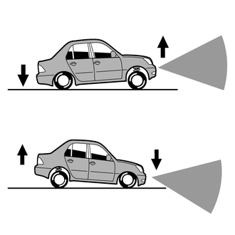
(5) Others
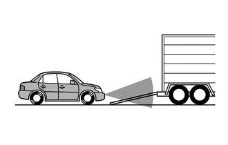
CASES OF UNNECESSARY REAR CROSS TRAFFIC AUTO BRAKE FUNCTION OPERATION
(a) In the following situations, the rear cross traffic auto brake function may operate even when there is no possibility of a collision:
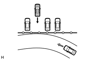
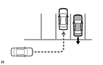
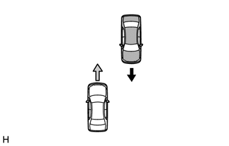
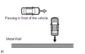
MULTI-INFORMATION DISPLAY AND HEADUP DISPLAY (w/ Headup Display System)
(a) Intelligent clearance sonar system display
(b) Intelligent clearance sonar system operation status display
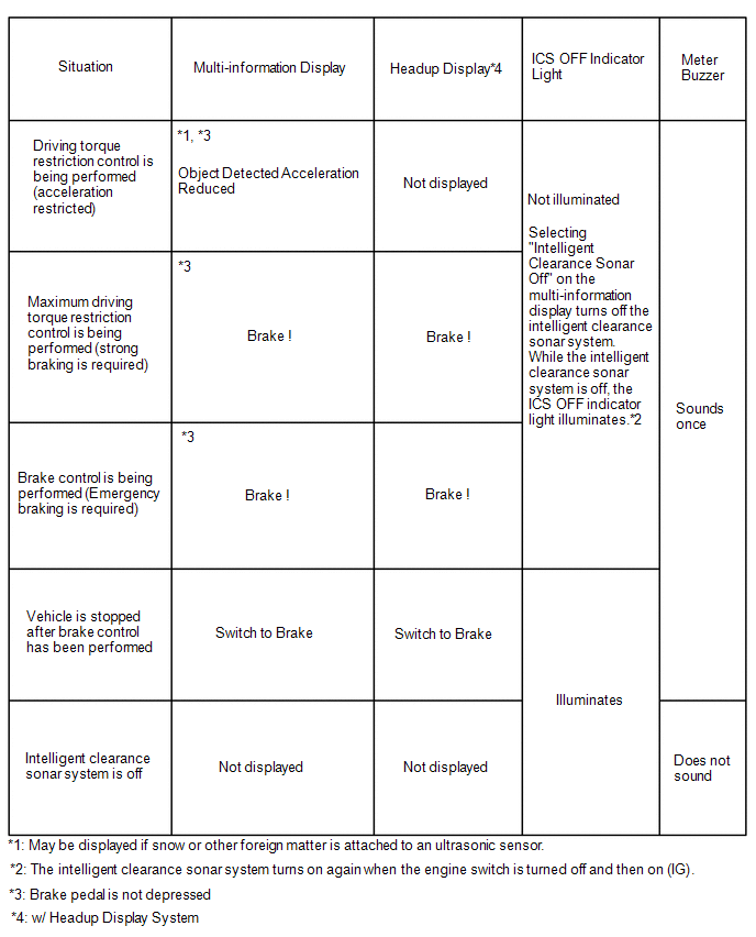
(c) Intelligent clearance sonar system warning display
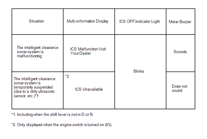
(d) Intelligent clearance sonar system off display
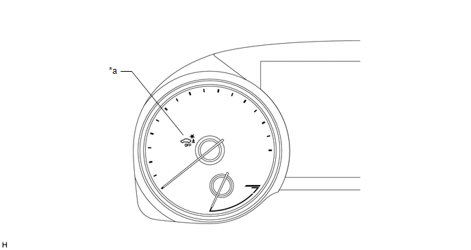
|
*a | ICS OFF Indicator |
- | - |
SYSTEM DIAGRAM
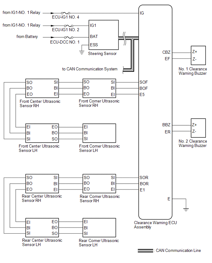
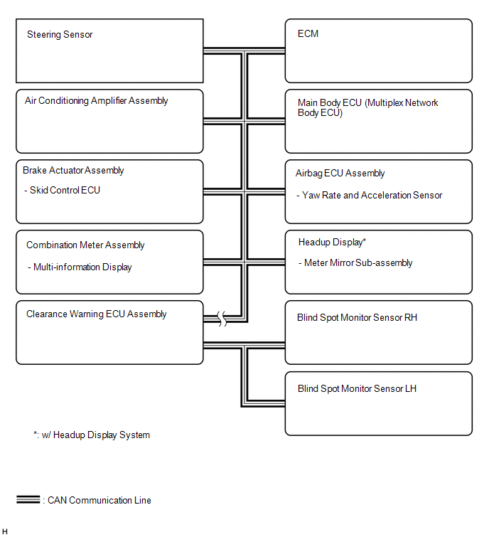 Communication Table
 |
Sender | Receiver |
Signal | Line |
|---|---|---|---|
|
Clearance Warning ECU Assembly | Combination Meter Assembly |
| CAN Communication Line |
|
ECM | Clearance Warning ECU Assembly |
Engine speed signal | CAN Communication Line |
|
Airbag ECU Assembly | Clearance Warning ECU Assembly |
Yaw rate and acceleration sensor signal |
CAN Communication Line |
| Combination Meter Assembly |
Clearance Warning ECU Assembly | Vehicle speed signal |
CAN Communication Line |
| Steering Sensor |
Clearance Warning ECU Assembly | Steering angle signal |
CAN Communication Line |
| Skid Control ECU |
Clearance Warning ECU Assembly |
| CAN Communication Line |
|
Air Conditioning Amplifier Assembly |
Clearance Warning ECU Assembly |
Ambient temperature signal |
CAN Communication Line |
|
Main Body ECU (Multiplex Network Body ECU) |
Clearance Warning ECU Assembly |
Vehicle information signal |
CAN Communication Line |
|
Clearance Warning ECU Assembly |
Meter Mirror Sub-assembly* |
Control status signal | CAN Communication Line |
|
Blind Spot Monitor Sensor (LH/RH) | Clearance Warning ECU Assembly |
Blind spot monitor system status signals |
CAN Communication Line |
TERMINALS OF ECU
CLEARANCE WARNING ECU ASSEMBLY

(a) Disconnect the K34 clearance warning ECU assembly connector.
(b) Measure the voltage and resistance on the wire harness side connector according to the value(s) in the table below.
|
Terminal No. (Symbol) | Wiring Color |
Terminal Description | Condition |
Specified Condition |
|---|---|---|---|---|
|
K34-1 (IG) - K34-30 (E) |
B - BR | IG engine source signal |
Engine switch off | Below 1 V |
|
Engine switch on (IG) |
11 to 14 V | |||
|
K34-30 (E) - Body ground |
BR - Body ground | Ground |
Always | Below 1 Ω |
(c) Reconnect the K34 clearance warning ECU assembly connector.
(d) Measure the voltage and check for pulses according to the value(s) in the table below.
|
Terminal No. (Symbol) | Wiring Color |
Terminal Description | Condition |
Specified Condition |
|---|---|---|---|---|
|
K34-4 (BOF) - K34-30 (E) |
R - BR | Power source for front sensor circuit |
Engine switch off | Below 1 V |
| 11 to 14 V | |||
|
K34-6 (E5) - K34-30 (E) |
W - BR | Ground for front clearance sonar |
Always | Below 1 Ω |
|
K34-8 (SOF) - K34-30 (E) |
L - BR | Front sensor communication signal (Front clearance sonar sensor) |
| Pulse generation (Refer to waveform 1) |
|
K34-14 (CBZ) - K34-13 (EF) |
LG - L | Clearance warning buzzer signal |
Buzzer sounding | Pulse generation (Refer to waveform 2) |
|
K34-22 (BOR) - K34-30 (E) |
BE - BR | Power source for rear sensor circuit |
Engine switch off | Below 1 V |
| 11 to 14 V | |||
|
K34-23 (E1) - K34-30 (E) |
GR - BR | Ground for rear clearance sonar |
Always | Below 1 Ω |
|
K34-24 (SOR) - K34-30 (E) |
SB - BR | Rear sensor communication signal (Rear clearance sonar sensor) |
| Pulse generation (Refer to waveform 3) |
(e) Using an oscilloscope, check waveform 1.
(1) Waveform 1 (Reference)
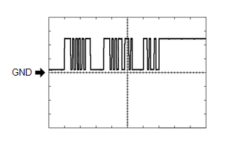
|
Item | Content |
|---|---|
|
Measurement terminal | K34-8 (SOF) - K34-30 (E) |
|
Measurement setting | 5 V/DIV., 1 ms./DIV. |
|
Condition |
|
(f) Using an oscilloscope, check waveform 2.
(1) Waveform 2 (Reference)
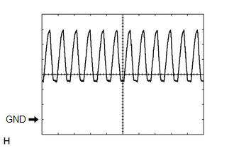
|
Item | Content |
|---|---|
|
Measurement terminal | K34-14 (CBZ) - K34-13 (EF) |
|
Measurement setting | 2 V/DIV., 500 μs./DIV. |
|
Condition | Buzzer sounding |
HINT:
The amplitude of the waveform changes according to the set volume.
(g) Using an oscilloscope, check waveform 3.
(1) Waveform 3 (Reference)
|
Item | Content |
|---|---|
|
Measurement terminal | K34-24 (SOR) - K34-30 (E) |
|
Measurement setting | 5 V/DIV., 1 ms./DIV. |
|
Condition |
|
COMBINATION METER ASSEMBLY
Click here

ECM
Click here
DESCRIPTION
This DTC is stored when the blind spot monitor sensor LH judges that there is a communication problem with the blind spot monitor sensor RH.
|
DTC No. | Detection Item |
DTC Detection Condition | Trouble Area |
|---|---|---|---|
|
U0232 | Lost Communication with Blind Spot Monitor Slave Module |
The clearance warning ECU assembly cannot receive signals from the blind spot monitor sensor (slave) |
|
| U0233 |
Lost Communication with Blind Spot Monitor Master Module |
The clearance warning ECU assembly cannot receive signals from the blind spot monitor sensor (master) |
|
WIRING DIAGRAM
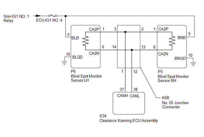
CAUTION / NOTICE / HINT
NOTICE:
Click here 
HINT:
PROCEDURE
|
1. | CHECK DTC |
(a) Check for DTCs.
Body Electrical > Advanced Parking Guidance/ICS/Intuitive P/A > Trouble Codes|
Result | Proceed to |
|---|---|
|
DTC U0232 is only output |
A |
| DTC U0233 is only output |
B |
| DTC U0232 and U0233 are output |
C |
| B |
 | GO TO STEP 5 |
| C |
| GO TO STEP 8 |
|
| 2. |
CHECK CAN BUS MAIN WIRE |
(a) Disconnect the cable from the negative (-) battery terminal.
(b) Disconnect the P6 blind spot monitor sensor LH connector.
| (c) Measure the resistance according to the value(s) in the table below. Standard Resistance:
|
|
| NG | | REPAIR OR REPLACE CAN MAIN WIRE OR CONNECTOR (BLIND SPOT MONITOR SENSOR LH - No. 26 JUNCTION CONNECTOR) |
|
| 3. |
CHECK HARNESS AND CONNECTOR (BLIND SPOT MONITOR SENSOR LH - BODY GROUND) |
Click here
| NG | | REPAIR OR REPLACE CAN MAIN WIRE OR CONNECTOR (BLIND SPOT MONITOR SENSOR LH - No. 26 JUNCTION CONNECTOR) |
|
| 4. |
CHECK HARNESS AND CONNECTOR (BLIND SPOT MONITOR SENSOR LH POWER SOURCE) |
Click here
| OK | | REPLACE BLIND SPOT MONITOR SENSOR LH |
| NG | | REPAIR OR REPLACE HARNESS OR CONNECTOR |
| 5. |
CHECK CAN BUS MAIN WIRE |
(a) Disconnect the cable from the negative (-) battery terminal.
(b) Disconnect the P5 blind spot monitor sensor RH connector.
| (c) Measure the resistance according to the value(s) in the table below. Standard Resistance:
|
|
| NG | | REPAIR OR REPLACE CAN MAIN WIRE OR CONNECTOR (BLIND SPOT MONITOR SENSOR RH - No. 26 JUNCTION CONNECTOR) |
|
| 6. |
CHECK HARNESS AND CONNECTOR (BLIND SPOT MONITOR SENSOR RH - BODY GROUND) |
Click here
| NG | | REPAIR OR REPLACE CAN MAIN WIRE OR CONNECTOR (BLIND SPOT MONITOR SENSOR LH - No. 26 JUNCTION CONNECTOR) |
|
| 7. |
CHECK HARNESS AND CONNECTOR (BLIND SPOT MONITOR SENSOR RH POWER SOURCE) |
Click here
| OK | | REPLACE BLIND SPOT MONITOR SENSOR RH |
| NG | | REPAIR OR REPLACE HARNESS OR CONNECTOR |
| 8. |
CHECK CAN BUS MAIN WIRE (BLIND SPOT MONITOR SENSOR LH) |
(a) Turn the engine switch off.
(b) Disconnect the cable from the negative (-) battery terminal.
| (c) Measure the resistance according to the value(s) in the table below. Standard Resistance:
|
|
|
Result | Proceed to |
|---|---|
|
OK | A |
|
Open circuit in CAN main bus lines |
B |
| Short circuit between bus lines |
C |
| D |
| B |
| GO TO STEP 11 |
| C |
| GO TO STEP 15 |
| D |
| GO TO STEP 19 |
|
| 9. |
CONFIRM CAN BUS WIRE (CLEARANCE WARNING ECU ASSEMBLY) |
(a) Disconnect the K34 clearance warning ECU assembly connector.
| (b) Measure the resistance according to the value(s) in the table below. Standard Resistance:
|
|
| NG | | REPAIR OR REPLACE CAN BUS WIRE (CLEARANCE WARNING ECU ASSEMBLY - No. 26 JUNCTION CONNECTOR) |
|
| 10. |
CHECK DTC |
(a) Clear the DTCs.
Body Electrical > Advanced Parking Guidance/ICS/Intuitive P/A > Clear DTCs(b) Check for DTCs.
Body Electrical > Advanced Parking Guidance/ICS/Intuitive P/A > Trouble Codes|
Result | Proceed to |
|---|---|
|
DTC U0232 and U0233 are output |
A |
| DTC U0232 and U0233 are not output |
B |
| A |
| REPLACE CLEARANCE WARNING ECU ASSEMBLY |
| B |
| USE SIMULATION METHOD TO CHECK |
| 11. |
CHECK FOR OPEN IN CAN BUS WIRE (No. 26 JUNCTION CONNECTOR) |
| (a) Disconnect the K68 No. 26 junction connector. |
|
(b) Measure the resistance according to the value(s) in the table below.
Standard Resistance:
|
Tester Connection | Condition |
Specified Condition |
|---|---|---|
|
K68-3 (CANH) - K68-14(CANL) |
Cable disconnected from negative (-) battery terminal |
108 to 132 Ω |
|
K68-2 (CANH) - K68-13 (CANL) |
Cable disconnected from negative (-) battery terminal |
108 to 132 Ω |
|
K68-1 (CANH) - K68-12(CANL) | Cable disconnected from negative (-) battery terminal |
200 Ω or higher |
|
Result | Proceed to |
|---|---|
|
OK | A |
|
NG (to blind spot monitor sensor RH CAN main wire) |
B |
| NG (to blind spot monitor sensor LH CAN main wire) |
C |
| NG (to clearance warning ECU assembly CAN wire) |
D |
| A |
| REPLACE No. 26 JUNCTION CONNECTOR |
| C |
| GO TO STEP 13 |
| D |
| GO TO STEP 14 |
|
| 12. |
CHECK FOR OPEN IN CAN BUS MAIN WIRE (BLIND SPOT MONITOR SENSOR RH) |
(a) Reconnect the K68 No. 26 junction connector.
| (b) Disconnect the P5 blind spot monitor sensor RH connector. |
|
(c) Measure the resistance according to the value(s) in the table below.
Standard Resistance:
|
Tester Connection | Condition |
Specified Condition |
|---|---|---|
|
P5-1 (CA2P) - P5-6 (CA2N) |
Cable disconnected from negative (-) battery terminal |
108 to 132 Ω |
| OK | | REPLACE BLIND SPOT MONITOR SENSOR RH |
| NG | | REPAIR OR REPLACE CAN MAIN WIRE OR CONNECTOR (BLIND SPOT MONITOR SENSOR RH - No. 26 JUNCTION CONNECTOR) |
| 13. |
CHECK FOR OPEN IN CAN BUS MAIN WIRE (BLIND SPOT MONITOR SENSOR LH) |
(a) Reconnect the K68 No. 26 junction connector.
| (b) Disconnect the P6 blind spot monitor sensor LH connector. |
|
(c) Measure the resistance according to the value(s) in the table below.
Standard Resistance:
|
Tester Connection | Condition |
Specified Condition |
|---|---|---|
|
P6-1 (CA2P) -P6-6 (CA2N) |
Cable disconnected from negative (-) battery terminal |
108 to 132 Ω |
| OK | | REPLACE BLIND SPOT MONITOR SENSOR LH |
| NG | | REPAIR OR REPLACE CAN MAIN WIRE OR CONNECTOR (BLIND SPOT MONITOR SENSOR LH - No. 26 JUNCTION CONNECTOR) |
| 14. |
CHECK FOR OPEN IN CAN BUS WIRE (CLEARANCE WARNING ECU ASSEMBLY) |
(a) Reconnect the K68 No. 26 junction connector.
| (b) Disconnect the K34 clearance warning ECU assembly connector. |
|
(c) Measure the resistance according to the value(s) in the table below.
Standard Resistance:
|
Tester Connection | Condition |
Specified Condition |
|---|---|---|
|
K34-37(CANH) - K34-38(CANL) |
Cable disconnected from negative (-) battery terminal |
54 to 69 Ω |
| OK | | REPLACE CLEARANCE WARNING ECU ASSEMBLY |
| NG | | REPAIR OR REPLACE CAN BUS WIRE (CLEARANCE WARNING ECU ASSEMBLY - No. 26 JUNCTION CONNECTOR) |
| 15. |
CHECK FOR SHORT IN CAN BUS WIRES (No. 26 JUNCTION CONNECTOR) |
| (a) Disconnect the K68 No. 26 junction connector. |
|
(b) Measure the resistance according to the value(s) in the table below.
Standard Resistance:
|
Tester Connection | Condition |
Specified Condition |
|---|---|---|
|
K68-3 (CANH) - K68-14(CANL) |
Cable disconnected from negative (-) battery terminal |
108 to 132 Ω |
|
K68-2 (CANH) - K68-13(CANL) |
Cable disconnected from negative (-) battery terminal |
108 to 132 Ω |
|
K68-1 (CANH) - K68-12(CANL) |
Cable disconnected from negative (-) battery terminal |
200 Ω or higher |
|
Result | Proceed to |
|---|---|
|
OK | A |
|
NG (to blind spot monitor sensor RH CAN main wire) |
B |
| NG (to blind spot monitor sensor LH CAN main wire) |
C |
| NG (to clearance warning ECU assembly CAN wire) |
D |
| A |
| REPLACE No. 26 JUNCTION CONNECTOR |
| C |
| GO TO STEP 17 |
| D |
| GO TO STEP 18 |
|
| 16. |
CHECK FOR SHORT IN CAN BUS WIRES (BLIND SPOT MONITOR SENSOR RH) |
(a) Reconnect the K68 No. 26 junction connector.
| (b) Disconnect the P5 blind spot monitor sensor RH connector. |
|
(c) Measure the resistance according to the value(s) in the table below.
Standard Resistance:
|
Tester Connection | Condition |
Specified Condition |
|---|---|---|
|
P5-1 (CA2P) - P5-6 (CA2N) |
Cable disconnected from negative (-) battery terminal |
108 to 132 Ω |
| OK | | REPLACE BLIND SPOT MONITOR SENSOR RH |
| NG | | REPAIR OR REPLACE CAN MAIN WIRE OR CONNECTOR (BLIND SPOT MONITOR SENSOR RH - No. 26 JUNCTION CONNECTOR) |
| 17. |
CHECK FOR SHORT IN CAN BUS WIRES (BLIND SPOT MONITOR SENSOR LH) |
(a) Reconnect the K68 No. 26 junction connector.
| (b) Disconnect the P6 blind spot monitor sensor LH connector. |
|
(c) Measure the resistance according to the value(s) in the table below.
Standard Resistance:
|
Tester Connection | Condition |
Specified Condition |
|---|---|---|
|
P6-1 (CA2P) -P6-6 (CA2N) |
Cable disconnected from negative (-) battery terminal |
108 to 132 Ω |
| OK | | REPLACE BLIND SPOT MONITOR SENSOR LH |
| NG | | REPAIR OR REPLACE CAN MAIN WIRE OR CONNECTOR (BLIND SPOT MONITOR SENSOR LH - No. 26 JUNCTION CONNECTOR) |
| 18. |
CHECK FOR SHORT IN CAN BUS WIRES (CLEARANCE WARNING ECU ASSEMBLY) |
(a) Reconnect the K68 No. 26 junction connector.
| (b) Disconnect the K34 clearance warning ECU assembly connector. |
|
(c) Measure the resistance according to the value(s) in the table below.
Standard Resistance:
|
Tester Connection | Condition |
Specified Condition |
|---|---|---|
|
K34-37(CANH) - K34-38(CANL) |
Cable disconnected from negative (-) battery terminal |
54 to 69 Ω |
| OK | | REPLACE CLEARANCE WARNING ECU ASSEMBLY |
| NG | | REPAIR OR REPLACE CAN BUS WIRE (CLEARANCE WARNING ECU ASSEMBLY - No. 26 JUNCTION CONNECTOR) |
| 19. |
CHECK FOR SHORT IN CAN BUS WIRES (No. 26 JUNCTION CONNECTOR) |
(a) Disconnect the K68 No. 26 junction connector.
(b) Measure the resistance according to the value(s) in the table below.
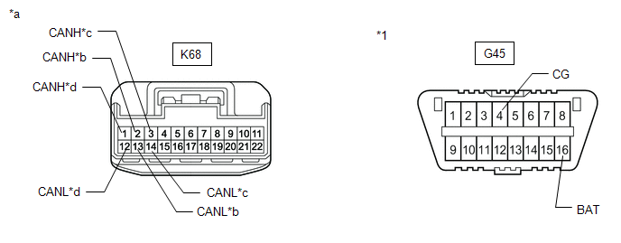
|
*1 | DLC3 |
- | - |
|
*a | Front view of wire harness connector (to No. 26 Junction Connector) |
*b | to Blind Spot Monitor Sensor RH CAN main wire |
|
*c | to Blind Spot Monitor Sensor LH CAN main wire |
*d | to Clearance Warning ECU Assembly CAN wire |
Standard Resistance:
|
Tester Connection | Condition |
Specified Condition |
|---|---|---|
|
K68-3 (CANH) - G45-4 (CG) |
Cable disconnected from negative (-) battery terminal |
200 Ω or higher |
|
K68-14 (CANL) - G45-4 (CG) |
Cable disconnected from negative (-) battery terminal |
200 Ω or higher |
|
K68-3 (CANH) - G45-16 (BAT) |
Cable disconnected from negative (-) battery terminal |
6 kΩ or higher |
|
K68-14 (CANL) - G45-16 (BAT) |
Cable disconnected from negative (-) battery terminal |
6 kΩ or higher |
|
K68-1 (CANH) - G45-4 (CG) |
Cable disconnected from negative (-) battery terminal |
200 Ω or higher |
|
K68-12 (CANL) - G45-4 (CG) |
Cable disconnected from negative (-) battery terminal |
200 Ω or higher |
|
K68-1 (CANH) - G45-16 (BAT) |
Cable disconnected from negative (-) battery terminal |
6 kΩ or higher |
|
K68-12 (CANL) - G45-16 (BAT) |
Cable disconnected from negative (-) battery terminal |
6 kΩ or higher |
|
K68-2 (CANH) - G45-4 (CG) |
Cable disconnected from negative (-) battery terminal |
200 Ω or higher |
|
K68-13 (CANL) - G45-4 (CG) |
Cable disconnected from negative (-) battery terminal |
200 Ω or higher |
|
K68-2 (CANH) - G45-16 (BAT) |
Cable disconnected from negative (-) battery terminal |
6 kΩ or higher |
|
K68-13 (CANL) - G45-16 (BAT) |
Cable disconnected from negative (-) battery terminal |
6 kΩ or higher |
|
Result | Proceed to |
|---|---|
|
OK | A |
|
NG (to blind spot monitor sensor RH CAN main wire) |
B |
| NG (to blind spot monitor sensor LH CAN main wire) |
C |
| NG (to clearance warning ECU assembly CAN wire) |
D |
| A |
| REPLACE No. 26 JUNCTION CONNECTOR |
| C |
| GO TO STEP 21 |
| D |
| GO TO STEP 22 |
|
| 20. |
CHECK FOR SHORT IN CAN BUS WIRES (BLIND SPOT MONITOR SENSOR RH) |
(a) Reconnect the K68 No. 26 junction connector.
(b) Disconnect the P5 blind spot monitor sensor RH connector.
| (c) Measure the resistance according to the value(s) in the table below. Standard Resistance:
|
|
| OK | | REPLACE BLIND SPOT MONITOR SENSOR RH |
| NG | | REPAIR OR REPLACE CAN MAIN WIRE OR CONNECTOR (BLIND SPOT MONITOR SENSOR RH - No. 26 JUNCTION CONNECTOR) |
| 21. |
CHECK FOR SHORT IN CAN BUS WIRES (BLIND SPOT MONITOR SENSOR LH) |
(a) Reconnect the K68 No. 26 junction connector.
(b) Disconnect the P6 blind spot monitor sensor LH connector.
| (c) Measure the resistance according to the value(s) in the table below. Standard Resistance:
|
|
| OK | | REPLACE BLIND SPOT MONITOR SENSOR LH |
| NG | | REPAIR OR REPLACE CAN MAIN WIRE OR CONNECTOR (BLIND SPOT MONITOR SENSOR LH - No. 26 JUNCTION CONNECTOR) |
| 22. |
CHECK FOR SHORT IN CAN BUS WIRES (CLEARANCE WARNING ECU ASSEMBLY) |
(a) Reconnect the K68 No. 26 junction connector.
| (b) Disconnect the K34 clearance warning ECU assembly connector. |
|
(c) Measure the resistance according to the value(s) in the table below.
Standard Resistance:
|
Tester Connection | Condition |
Specified Condition |
|---|---|---|
|
K34-37 (CANH) - G45-4 (CG) |
Cable disconnected from negative (-) battery terminal |
200 Ω or higher |
|
K34-38 (CANL) - G45-4 (CG) |
Cable disconnected from negative (-) battery terminal |
200 Ω or higher |
|
K34-37 (CANH) - G45-16 (BAT) |
Cable disconnected from negative (-) battery terminal |
6 kΩ or higher |
|
K34-38 (CANL) - G45-16 (BAT) |
Cable disconnected from negative (-) battery terminal |
6 kΩ or higher |
| OK | | REPLACE CLEARANCE WARNING ECU ASSEMBLY |
| NG | | REPAIR OR REPLACE CAN BUS WIRE (CLEARANCE WARNING ECU ASSEMBLY - No. 26 JUNCTION CONNECTOR) |
DESCRIPTION
When the clearance warning ECU assembly determines that the CAN communication circuit is malfunctioning during self diagnosis, DTC U1000 is stored.
|
DTC No. | Detection Item |
DTC Detection Condition | Trouble Area |
|---|---|---|---|
|
U1000 | CAN Communication Failure (Message Registry) |
CAN communication circuit malfunction is detected |
Clearance warning ECU assembly |
PROCEDURE
| 1. |
CHECK FOR DTC |
(a) Using the Techstream, check for DTCs according to the prompts on the screen.
HINT:
After turning the engine switch from off to on (IG), wait 10 seconds or more before checking for DTCs.
Body Electrical > Advanced Parking Guidance/ICS/Intuitive P/A > Trouble Codes(b) Clear the DTCs according to the screen on the Techstream.
Body Electrical > Advanced Parking Guidance/ICS/Intuitive P/A > Clear DTCs(c) Recheck for DTCs.
Body Electrical > Advanced Parking Guidance/ICS/Intuitive P/A > Trouble CodesOK:
DTC U1000 is not output.
HINT:
Click here 
| OK |  | USE SIMULATION METHOD TO CHECK |
| NG | | REPLACE CLEARANCE WARNING ECU ASSEMBLY |
UTILITY
FREEZE FRAME DATA
NOTICE:
HINT:
The freeze frame data that is stored and updated each time the brakes are operated is stored in a different area to that of DTC freeze frame data.
(a) Connect the Techstream to the DLC3.
(b) Turn the engine switch on (IG).
(c) Turn the Techstream on.
(d) Enter the following menus: Body Electrical /Advanced Parking Guidance/ICS/Intuitive P/A / Utility.
(e) Read the Utility according to the display on the Techstream.
Body Electrical > Advanced Parking Guidance/ICS/Intuitive P/A > Utility|
Tester Display |
|---|
| Operative/Inoperative Condition History |
|
Tester Display | Measurement Item |
Range | Normal Condition |
Diagnostic Note |
|---|---|---|---|---|
| Distance to an object detected by ICS control |
The calculated distance to an object detected by the front/rear sensors when the vehicle is moving forward/backward |
Unknown, Not Detected or 0 to 3.78 m | Unknown: Detection conditions not met Not Detected: No objects detected 0 to 3.78 m: Distance to a detected object |
- |
| Shift State |
Shift state | P, R, N or D |
P: Park (P) selected R: Reverse (R) selected N: Neutral (N) selected D: Drive (D) selected | - |
|
Accelerator pedal opening angle | Accelerator pedal opening angle |
0 to 124% | Accelerator pedal opening angle displayed |
- |
| Vehicle speed |
Vehicle speed | 0 to 9.45 m/s |
Actual vehicle speed displayed |
- |
| Steering angle |
Absolute steering wheel angle |
0 to 630° | Absolute steering wheel angle displayed |
- |
| Steering wheel turning direction |
Steering wheel turning direction |
Left or Right | Left: Steering wheel being turned left Right: Steering wheel being turned right |
- |
| Accelerator ON judgment |
Judged accelerator pedal status |
OFF or ON | ON: Accelerator pedal depressed OFF: Accelerator pedal released |
- |
| Brake ON judgment |
Judged brake pedal status | OFF or ON |
ON: Brake pedal depressed OFF: Brake pedal released |
- |
| Brake request |
Pre-collision brake control request status |
OFF or ON | ON: Pre-collision brake control requested OFF: Pre-collision brake control not requested |
- |
| ICS Temporarily Not Available (Shift Position Invalid) |
Intelligent clearance sonar system temporarily not useable as shift position indeterminable |
Available or Not Available |
Available:OK Not Available: Temporarily not useable as shift position indeterminable |
- |
| ICS Temporarily Not Available (Steering Angle Neutral Point) |
Intelligent clearance sonar system temporarily not useable as steering angle neutral point not memorized |
Available or Not Available |
Available:OK Not Available: Temporarily not useable as steering sensor neutral point not memorized |
- |
| ICS Temporarily Not Available (IG Voltage Low) |
Intelligent clearance sonar system temporarily not useable due to low voltage of supply power from battery |
Available or Not Available |
Available:OK Not Available: Temporarily not useable due to low voltage of supply power from battery |
- |
| ICS Temporarily Not Available (Sensor Temporarily Not Available) |
Intelligent clearance sonar system temporarily not useable due to malfunction caused by an ultrasonic sensor |
Available or Not Available |
Available:OK Not Available: Temporarily not useable due to ultrasonic sensor malfunction |
- |
| Front Left Center Sensor Obstructed |
Intuitive parking assist system temporarily not useable due to foreign matter on ultrasonic sensor |
No or Yes | No: No foreign matter attached Yes: Foreign matter attached |
- |
| Front Right Center Sensor Obstructed |
Intuitive parking assist system temporarily not useable due to foreign matter on ultrasonic sensor |
No or Yes | No: No foreign matter attached Yes: Foreign matter attached |
- |
| Rear Left Center Sensor Obstructed |
Intuitive parking assist system temporarily not useable due to foreign matter on ultrasonic sensor |
No or Yes | No: No foreign matter attached Yes: Foreign matter attached |
- |
| Rear Right Center Sensor Obstructed |
Intuitive parking assist system temporarily not useable due to foreign matter on ultrasonic sensor |
No or Yes | No: No foreign matter attached Yes: Foreign matter attached |
- |
| Front Left Sensor Dirty |
Intuitive parking assist system temporarily not useable due to dirty ultrasonic sensor |
No or Yes | No: Not dirty Yes: Dirty | - |
|
Front Left Center Sensor Dirty |
Intuitive parking assist system temporarily not useable due to dirty ultrasonic sensor |
No or Yes | No: Not dirty Yes: Dirty | - |
|
Front Right Center Sensor Dirty |
Intuitive parking assist system temporarily not useable due to dirty ultrasonic sensor |
No or Yes | No: Not dirty Yes: Dirty | - |
|
Front Right Sensor Dirty | Intuitive parking assist system temporarily not useable due to dirty ultrasonic sensor |
No or Yes | No: Not dirty Yes: Dirty | - |
|
Rear Left Sensor Dirty | Intuitive parking assist system temporarily not useable due to dirty ultrasonic sensor |
No or Yes | No: Not dirty Yes: Dirty | - |
|
Rear Left Center Sensor Dirty |
Intuitive parking assist system temporarily not useable due to dirty ultrasonic sensor |
No or Yes | No: Not dirty Yes: Dirty | - |
|
Rear Right Center Sensor Dirty |
Intuitive parking assist system temporarily not useable due to dirty ultrasonic sensor |
No or Yes | No: Not dirty Yes: Dirty | - |
|
Rear Right Sensor Dirty | Intuitive parking assist system temporarily not useable due to dirty ultrasonic sensor |
No or Yes | No: Not dirty Yes: Dirty | - |
|
Front Left Sensor Malfunction (Temporarily) |
Intuitive parking assist system temporarily not useable due to ultrasonic sensor internal failure |
No or Yes | No: No internal failure Yes: Internal failure | - |
|
Front Left Center Sensor Malfunction (Temporarily) |
Intuitive parking assist system temporarily not useable due to ultrasonic sensor internal failure |
No or Yes | No: No internal failure Yes: Internal failure | - |
|
Front Right Center Sensor Malfunction (Temporarily) |
Intuitive parking assist system temporarily not useable due to ultrasonic sensor internal failure |
No or Yes | No: No internal failure Yes: Internal failure | - |
|
Front Right Sensor Malfunction (Temporarily) |
Intuitive parking assist system temporarily not useable due to ultrasonic sensor internal failure |
No or Yes | No: No internal failure Yes: Internal failure | - |
|
Rear Left Sensor Malfunction (Temporarily) |
Intuitive parking assist system temporarily not useable due to ultrasonic sensor internal failure |
No or Yes | No: No internal failure Yes: Internal failure | - |
|
Rear Left Center Sensor Malfunction (Temporarily) |
Intuitive parking assist system temporarily not useable due to ultrasonic sensor internal failure |
No or Yes | No: No internal failure Yes: Internal failure | - |
|
Rear Right Center Sensor Malfunction (Temporarily) |
Intuitive parking assist system temporarily not useable due to ultrasonic sensor internal failure |
No or Yes | No: No internal failure Yes: Internal failure | - |
|
Rear Right Sensor Malfunction (Temporarily) |
Intuitive parking assist system temporarily not useable due to ultrasonic sensor internal failure |
No or Yes | No: No internal failure Yes: Internal failure | - |
|
Front Left Sensor Obstructed |
Intuitive parking assist system temporarily not useable due to foreign matter on ultrasonic sensor |
No or Yes | No: No foreign matter attached Yes: Foreign matter attached |
- |
| Front Right Sensor Obstructed |
Intuitive parking assist system temporarily not useable due to foreign matter on ultrasonic sensor |
No or Yes | No: No foreign matter attached Yes: Foreign matter attached |
- |
| Rear Left Sensor Obstructed |
Intuitive parking assist system temporarily not useable due to foreign matter on ultrasonic sensor |
No or Yes | No: No foreign matter attached Yes: Foreign matter attached |
- |
| Rear Right Sensor Obstructed |
Intuitive parking assist system temporarily not useable due to foreign matter on ultrasonic sensor |
No or Yes | No: No foreign matter attached Yes: Foreign matter attached |
- |
| RCTAB Controlled Object Relative Position (X) |
Displays the distance of an object relative to the position of the vehicle when reversing |
-12.8 to 12.6 m | Actual distance is displayed |
- |
| RCTAB Controlled Object Relative Position (Y) |
Displays the distance of an object relative to the position of the vehicle when reversing |
-25.6 to 25.4 m | Actual distance is displayed |
- |
VEHICLE CONTROL HISTORY
Vehicle Control History
HINT:
Part of the control history can be confirmed using the vehicle control history.
Click here 
Toyota Avalon (XX50) 2019-2022 Service & Repair Manual > Door / Hatch: Front Door Opening Trim Weatherstrip
ComponentsCOMPONENTS ILLUSTRATION *1 COWL SIDE TRIM SUB-ASSEMBLY *2 FRONT DOOR OPENING TRIM WEATHERSTRIP *3 FRONT DOOR SCUFF PLATE - - InstallationINSTALLATION CAUTION / NOTICE / HINT HINT: Use the same procedure for the RH side and LH side. The following procedure is for the LH side. PROCEDURE 1. ...