COMPONENTS
ILLUSTRATION
|
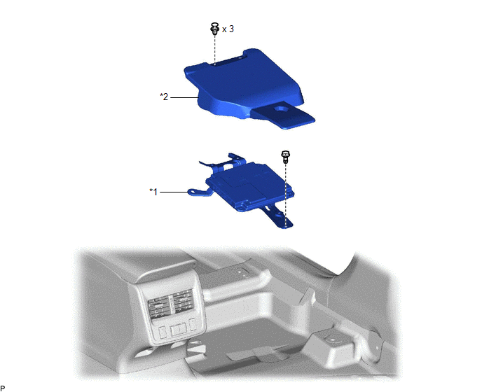
*1 | PARKING ASSIST ECU |
*2 | PARKING ASSIST ECU COVER |
INSTALLATION
PROCEDURE
1. INSTALL PARKING ASSIST ECU
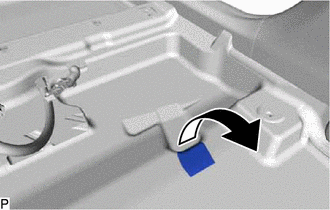
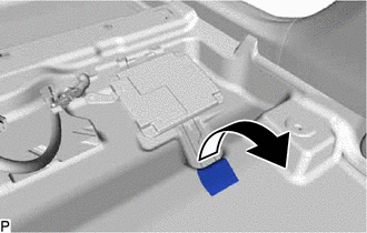
| (a) Turn back the front floor carpet assembly and front floor mat as shown in the illustration. |
|
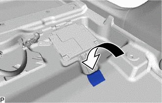
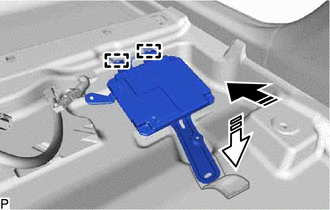
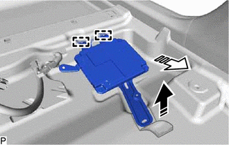
(b) Engage the 2 guides to temporarily install the parking assist ECU as shown in the illustration.
 |
Install in this Direction (1) |
 |
Install in this Direction (2) |
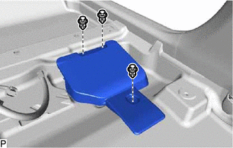
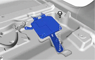
(c) Install the parking assist ECU with the bolt.
| (d) Install the front floor carpet assembly and front floor mat to its original position as shown in the illustration. |
|
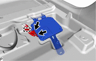
(e) Engage the clamp.
(f) Connect each connector.
2. INSTALL PARKING ASSIST ECU COVER
(a) Install the parking assist ECU cover with the 3 clips.
3. INSTALL FRONT SEAT ASSEMBLY RH
HINT:
Use the same procedure as for the LH side.
Click here

4. PERFORM CALIBRATION
for Gasoline Model: Click here
for HV Model: Click here
REMOVAL
CAUTION / NOTICE / HINT
The necessary procedures (adjustment, calibration, initialization, or registration) that must be performed after parts are removed and installed, or replaced during parking assist ECU removal/installation are shown below.
Necessary Procedure After Parts Removed/Installed/Replaced (for Gasoline Model)|
Replaced Part or Performed Procedure |
Necessary Procedure | Effect/Inoperative Function When Necessary Procedures are not Performed |
Link |
|---|---|---|---|
|
*: When performing learning using the Techstream.
Click here | |||
|
Disconnect cable from negative battery terminal |
Perform steering sensor zero point calibration |
Lane Departure Alert System (w/ Steering Control) |
|
|
Pre-collision System | |||
|
Intelligent Clearance Sonar System* | |||
|
Lighting System (for Gasoline Model with Cornering Light) | |||
|
Memorize steering angle neutral point |
Parking Assist Monitor System |
| |
|
Panoramic View Monitor System |
| ||
|
Replacement of parking assist ECU |
| Panoramic View Monitor System |
|
|
Front passenger seat | Zero point calibration (Occupant classification system) |
|
|
CAUTION:
Some of these service operations affect the SRS airbag system. Read the precautionary notices concerning the SRS airbag system before servicing.
Click here

 Necessary Procedure After Parts Removed/Installed/Replaced (for HV Model)
 |
Replaced Part or Performed Procedure |
Necessary Procedure | Effect/Inoperative Function When Necessary Procedures are not Performed |
Link |
|---|---|---|---|
|
*: When performing learning using the Techstream.
Click here | |||
|
Disconnect cable from negative auxiliary battery terminal |
Perform steering sensor zero point calibration |
Lane Departure Alert System (w/ Steering Control) |
|
|
Pre-collision System | |||
|
Intelligent Clearance Sonar System* | |||
|
Lighting System (for HV Model with Cornering Light) | |||
|
Memorize steering angle neutral point |
Parking Assist Monitor System |
| |
|
Panoramic View Monitor System |
| ||
|
Replacement of parking assist ECU |
| Panoramic View Monitor System |
|
|
Front passenger seat | Zero point calibration (Occupant classification system) |
|
|
CAUTION:
Some of these service operations affect the SRS airbag system. Read the precautionary notices concerning the SRS airbag system before servicing.
Click here
PROCEDURE
1. REMOVE FRONT SEAT ASSEMBLY RH
HINT:
Use the same procedure as for the LH side.
Click here
2. REMOVE PARKING ASSIST ECU COVER
| (a) Remove the 3 clips and parking assist ECU cover. |
|
3. REMOVE PARKING ASSIST ECU
| (a) Disconnect each connector. |
|
(b) Disengage the clamp.
|
(c) Turn back the front floor carpet assembly and front floor mat as shown in the illustration. |
|
| (d) Remove the bolt. |
|
(e) Disengage the 2 guides and remove the parking assist ECU as shown in the illustration.
 |
Remove in this Direction (1) |
 |
Remove in this Direction (2) |
Toyota Avalon (XX50) 2019-2022 Service & Repair Manual > Navigation System(for Gasoline Model): Radio Receiver Power Source Circuit. Registered Device cannot be Deleted. Reverse Signal Circuit between Radio Receiver Assembly and Navigation ECU
Radio Receiver Power Source Circuit DESCRIPTION This is the power source circuit to operate the radio and display receiver assembly. WIRING DIAGRAM CAUTION / NOTICE / HINT NOTICE: Inspect the fuses for circuits related to this system before performing the following procedure. PROCEDURE 1. CHECK HARN ...