DIAGNOSIS SYSTEM
DESCRIPTION
(a) Diagnostic Trouble Codes (DTCs) for the telematics system can be read from the Data Link Connector 3 (DLC3) of the vehicle. When the system seems to be malfunctioning, use the Techstream to check for malfunctions and to repair it.
CHECK DLC3
(a) Check the DLC3.
Click here

DIAGNOSTIC TROUBLE CODE CHART
Telematics System|
DTC No. | Detection Item |
Link |
|---|---|---|
| U0142 |
Lost Communication with Body Control Module "B" |
|
|
U0155 | Lost Communication with Instrument Panel Cluster (IPC) Control Module |
|
|
U0163 | Lost Communication with Navigation Control Module |
|
DTC CHECK / CLEAR
CHECK DTC
(a) Connect the Techstream to the DLC3.
(b) Turn the engine switch on (IG).
(c) Turn the Techstream on.
(d) Enter the following menus: Body Electrical / Telematics / Trouble Codes.
Body Electrical > Telematics > Trouble Codes(e) Check for DTCs.
Click here 
CLEAR DTC
(a) Connect the Techstream to the DLC3.
(b) Turn the engine switch on (IG).
(c) Turn the Techstream on.
(d) Enter the following menus: Body Electrical / Telematics / Trouble Codes.
Body Electrical > Telematics > Clear DTCs(e) Clear the DTCs.
CAUTION / NOTICE / HINT
HINT:
PROCEDURE
|
1. | VEHICLE BROUGHT TO WORKSHOP |
|
| 2. |
CUSTOMER PROBLEM ANALYSIS |
HINT:
|
What |
Vehicle model, system name |
|
When |
Date, time, occurrence frequency |
|
Where |
Road conditions |
|
Under what conditions? |
Driving conditions, weather conditions |
|
How did it happen? |
Problem symptoms |
|
| 3. |
INSPECT BATTERY |
(a) Measure the battery voltage.
Standard Voltage:
11 to 14 V
HINT:
If the voltage is below 11 V, recharge or replace the battery before proceeding to the next step.
|
| 4. |
CHECK CAN COMMUNICATION SYSTEM* |
(a) Check if CAN communication system DTCs are output.
Click here 
|
Result | Proceed to |
|---|---|
|
CAN DTCs are not output. |
A |
| CAN DTCs are output. |
B |
| B |
 | GO TO CAN COMMUNICATION SYSTEM |
|
| 5. |
CHECK DTC* |
(a) Check for DTCs.
Click here
Click here
|
Result | Proceed to |
|---|---|
|
DTCs are not output. |
A |
| Safety connect system DTCs are output. |
B |
| Telematics system DTCs are output. |
C |
| B |
| GO TO SAFETY CONNECT SYSTEM |
| C |
| GO TO DIAGNOSTIC TROUBLE CODE CHART |
|
| 6. |
PROBLEM SYMPTOMS TABLE |
(a) Refer to Problem Symptoms Table.
Click here
|
Result | Proceed to |
|---|---|
|
Fault is not listed in Problem Symptoms Table. |
A |
| Fault is listed in Problem Symptoms Table. |
B |
HINT:
If the symptom does not recur and no DTCs are output, perform the simulation method.
Click here
| B |
| GO TO STEP 8 |
|
| 7. |
PERFORM TROUBLESHOOTING* |
(a) Refer to Terminals of ECU.
Click here
|
| 8. |
REPAIR OR REPLACE |
|
| 9. |
CONFIRMATION TEST |
| NEXT | | END |
OPERATION CHECK
CHECK DCM OPERATION HISTORY
HINT:
This function is used to display operation factor data and time at which it was stored in the DCM (Telematics Transceiver).
(a) Check DCM Operation History
HINT:
When problem symptoms due to wave interference cannot be reproduced, this function provides DCM operation history information which can be used to explain the cause of the malfunction to the customer and/or contact the service center.
(1) Connect the Techstream to the DLC3.
(2) Turn the engine switch on (IG).
(3) Turn the Techstream on.
(4) Enter the following menus: Body Electrical / Telematics / Utility / DCM Operation History.
Body Electrical > Telematics > Utility|
Tester Display |
|---|
| DCM Operation History |
|
Item | Function |
Parameter Name |
|---|---|---|
| Request Type from Service Center |
Displays the type of request received from the service center. |
Remote Diagnostics |
| Remote Operation | ||
|
Remote Vehicle Status | ||
| Remote Immobiliser Set | ||
|
Remote Immobiliser Unset | ||
| Remote Guest Driver Status | ||
|
Remote Service Flag | ||
|
Remote Operation Type | Displays the type of remote operation request received from the service center. |
Hazard ON (Car Locator) |
| Hazard Lamp OFF | ||
|
Hazard Lamp OFF Cancel | ||
| Door Lock | ||
|
Door Unlock | ||
| Door Lock with Security Set | ||
|
Door Unlock with Security Unset | ||
| Power Window Close | ||
|
Power Window Close Cancel | ||
| Air Conditioner ON | ||
|
Air Conditioner OFF | ||
| Notification Preference Status 1 |
Displays whether a service flag received from the service center is turned on. |
Remote Warning |
| Remote Detected DTC | ||
|
Remote FFD | ||
| Remote Detect DTC | ||
|
Remote Vehicle Status | ||
| Remote Precaution | ||
|
Remote Monitoring | ||
| Remote DTC Recorder | ||
|
Notification Preference Status 2 |
Displays whether a service flag received from the service center is turned on. |
Remote Alarm Detect |
| Remote Operation | ||
|
Remote Immobiliser | ||
| Remote Vehicle Location | ||
|
Remote Navigation Display | ||
| Remote Guest Driver Status | ||
|
Notification Preference Status 3 |
Displays whether a service flag received from the service center is turned on. |
Remote A/C by Smart Key |
| Remote Service Function | ||
|
Remote Transmission Error | Displays the reason for failure if communication between the service center and DCM (Telematics Transceiver) failed. |
Priority Interruption |
| CDMA Out of Service | ||
|
Communication Failure | ||
| HTTP Time Out | ||
|
HTTP Status (Retry) | ||
| HTTP Status (No Retry) | ||
|
E-Mail Tag | ||
| E-Mail Data | ||
|
Center | ||
| Remote Door Lock and Unlock |
Displays operation factor data for when a remote door lock and unlock operation was performed. |
Success |
| Error (Priority Interruption) | ||
|
Error (CDMA Out of Service) | ||
| Error (Communication Failure) | ||
|
Error (HTTP Time Out) | ||
| Error (HTTP Status (Retried)) | ||
|
Error (HTTP Status (Not Retried)) | ||
|
Error (E-Mail Tag) | ||
| Error (E-Mail Data) | ||
|
Error (Service Center) | ||
| Error (Combination Rule) | ||
|
Error (Invalid Request) | ||
| Error (Delayed Receipt) | ||
|
Error (Invalid Time) | ||
| Error (Out of Operation) | ||
|
Cancel Failure (No Operation) | ||
| Cancel Failure (Day Elapse) | ||
|
Cancel Failure (IG/ACC ON) | ||
| Cancel Failure (Active Manually) | ||
|
Cancel Failure (Canceled) | ||
| Cancel Failure (Operation Failure) | ||
|
Rejected (IG/ACC ON) | ||
| Rejected (Under Repair) | ||
|
Rejected (Setting Not Operated) | ||
| Rejected (Received Inaccurate Data) | ||
|
Operated Manually | ||
| Door Open | ||
|
Trunk Lid Open | ||
| Hood Open | ||
|
Door Lock Operation | ||
| Key in the Vehicle | ||
|
Smart Cancel ON | ||
| Unable to Start the Engine | ||
|
Intrusion Sensor Error | ||
| Intruder Detected | ||
|
Lost Communication (Time Data) | ||
| Commu Error (Unmatched Time) | ||
|
Lost Communication (Periodical) | ||
| Communication Error (Periodical) | ||
|
Lost Communication (No Response) | ||
|
Communication Error (No Response) | ||
|
Commu Error (DCM ECU Error) | ||
| All Doors Locked | ||
|
One of Doors Unlocked | ||
| Coincidence Operation | ||
|
Unable to Lock | ||
| Unable to Unlock | ||
|
Lost CAN Communication (Reply) | ||
| CAN Communication Error (Reply) | ||
|
Remote Power Window* | Displays operation factor data for when a remote power window operation was performed. |
Success |
| Error (Priority Interruption) | ||
|
Error (CDMA Out of Service) | ||
| Error (Communication Failure) | ||
|
Error (HTTP Time Out) | ||
| Error (HTTP Status (Retried)) | ||
|
Error (HTTP Status (Not Retried)) | ||
|
Error (E-Mail Tag) | ||
| Error (E-Mail Data) | ||
|
Error (Service Center) | ||
| Error (Combination Rule) | ||
|
Error (Invalid Request) | ||
| Error (Delayed Receipt) | ||
|
Error (Invalid Time) | ||
| Error (Out of Operation) | ||
|
Cancel Failure (No Operation) | ||
| Cancel Failure (Day Elapse) | ||
|
Cancel Failure (IG/ACC ON) | ||
| Cancel Failure (Active Manually) | ||
|
Cancel Failure (Canceled) | ||
| Cancel Failure (Operation Failure) | ||
|
Rejected (IG/ACC ON) | ||
| Rejected (Under Repair) | ||
|
Rejected (Setting Not Operated) | ||
| Rejected (Received Inaccurate Data) | ||
|
Operated Manually | ||
| Door Open | ||
|
Trunk Lid Open | ||
| Hood Open | ||
|
Door Lock Operation | ||
| Key in the Vehicle | ||
|
Smart Cancel ON | ||
| Unable to Start the Engine | ||
|
Intrusion Sensor Error | ||
| Intruder Detected | ||
|
Lost Communication (Time Data) | ||
| Commu Error (Unmatched Time) | ||
|
Lost Communication (Periodical) | ||
| Communication Error (Periodical) | ||
|
Lost Communication (No Response) | ||
|
Communication Error (No Response) | ||
|
Commu Error (DCM ECU Error) | ||
| All Windows Closed | ||
|
One of Windows Opened | ||
| Coincidence Operation | ||
|
Jam Protection (Opened) | ||
| Jam Protection (Closed) | ||
|
P/W Error Detected | ||
| Power Supply Insufficiency | ||
|
P/W NOT Initialized | ||
| Lost CAN Communication (Reply) | ||
|
CAN Communication Error (Reply) | ||
|
Remote Engine Start and Stop |
Displays operation factor data for when a remote engine start and stop operation was performed. |
Success |
| Error (Priority Interruption) | ||
|
Error (CDMA Out of Service) | ||
| Error (Communication Failure) | ||
|
Error (HTTP Time Out) | ||
| Error (HTTP Status (Retried)) | ||
|
Error (HTTP Status (Not Retried)) | ||
|
Error (E-Mail Tag) | ||
| Error (E-Mail Data) | ||
|
Error (Service Center) | ||
| Error (Combination Rule) | ||
|
Error (Invalid Request) | ||
| Error (Delayed Receipt) | ||
|
Error (Invalid Time) | ||
| Error (Out of Operation) | ||
|
Cancel Failure (No Operation) | ||
| Cancel Failure (Day Elapse) | ||
|
Cancel Failure (IG/ACC ON) | ||
| Cancel Failure (Active Manually) | ||
|
Cancel Failure (Canceled) | ||
| Cancel Failure (Operation Failure) | ||
|
Rejected (IG/ACC ON) | ||
| Rejected (Under Repair) | ||
|
Rejected (Setting Not Operated) | ||
| Rejected (Received Inaccurate Data) | ||
|
Remote Engine Start and Stop | Displays operation factor data for when a remote engine start and stop operation was performed. |
Operated Manually |
| Door Open | ||
|
Trunk Lid Open | ||
| Hood Open | ||
|
Door Lock Operation | ||
| Key in the Vehicle | ||
|
Smart Cancel ON | ||
| Unable to Start the Engine | ||
|
Intrusion Sensor Error | ||
| Intruder Detected | ||
|
Lost Communication (Time Data) | ||
| Commu Error (Unmatched Time) | ||
|
Lost Communication (Periodical) | ||
| Communication Error (Periodical) | ||
|
Lost Communication (No Response) | ||
|
Communication Error (No Response) | ||
|
Commu Error (DCM ECU Error) | ||
| A/C OFF | ||
|
A/C Condition Failure | ||
| DCM ECU Low Voltage | ||
|
Accumulation Time Excess | ||
| A/C ON | ||
|
Remote Starter Connecting | ||
| A/C OFF Success | ||
|
Remote Starter Not Start | ||
| A/C OFF by Smart Key | ||
|
A/C OFF by Vehicle Operation | ||
| A/C OFF Past The Time Limit | ||
|
A/C OFF Low Voltage | ||
| Smart Key Operation Success | ||
|
Smart Key Operation Failure | ||
| Engine Start Failure | ||
|
IG ON Failure | ||
| A/C ON Failure | ||
|
A/C OFF Failure | ||
| Guest Driver Monitor |
Displays operation factor data for when a guest driver monitor operation was performed. |
Violation Notice |
| Violation Error (Priority Interruption) | ||
|
Violation Error (CDMA Out of Service) | ||
|
Violation Error (Communication Failure) | ||
|
Violation Error (HTTP Time Out) | ||
|
Violation Error (HTTP Status (Retry)) | ||
|
Violation Error (HTTP Status (No Retry)) | ||
|
Violation Error (E-Mail Tag) | ||
|
Violation Error (E-Mail Data) | ||
|
Violation Error (Center) | ||
| Update Notice | ||
|
Update Error (Priority Interruption) | ||
|
Update Error (CDMA Out of Service) | ||
|
Update Error (Communication Failure) | ||
|
Update Error (HTTP Time Out) | ||
|
Update Error (HTTP Status (Retry)) | ||
|
Update Error (HTTP Status (No Retry)) | ||
|
Update Error (E-Mail Tag) | ||
| Update Error (E-Mail Data) | ||
|
Update Error (Center) | ||
| Status Notice | ||
|
Status Error (Priority Interruption) | ||
|
Status Error (CDMA Out of Service) | ||
|
Status Error (Communication Failure) | ||
|
Status Error (HTTP Time Out) | ||
|
Status Error (HTTP Status (Retry)) | ||
|
Status Error (HTTP Status (No Retry)) | ||
|
Status Error (E-Mail Tag) | ||
| Status Error (E-Mail Data) | ||
|
Status Error (Center) | ||
| Result Notice | ||
|
Result Error (Priority Interruption) | ||
|
Result Error (CDMA Out of Service) | ||
|
Result Error (Communication Failure) | ||
|
Result Error (HTTP Time Out) | ||
|
Result Error (HTTP Status (Retry)) | ||
|
Result Error (HTTP Status (No Retry)) | ||
|
Result Error (E-Mail Tag) | ||
| Result Error (E-Mail Data) | ||
|
Result Error (Center) | ||
|
Vehicle Status Report | Displays operation factor data for when a vehicle status report operation was performed. |
Forget Notice |
| Forget Notice Failure (Interrupt) | ||
|
Forget Notice Failure (Other) | ||
| Vehicle Status | ||
|
Vehicle Status Failure (Interrupt) | ||
|
Vehicle Status Failure (Other) | ||
|
Vehicle Status Connect Scantool | ||
|
Vehicle Status Connect Scantool (Inter) | ||
|
Vehicle Status Connect Scantool (Other) | ||
|
Forget Notice Connect Scantool | ||
|
Forget Notice Connect Scantool (Inter) | ||
|
Forget Notice Connect Scantool (Other) |
PARTS LOCATION
ILLUSTRATION
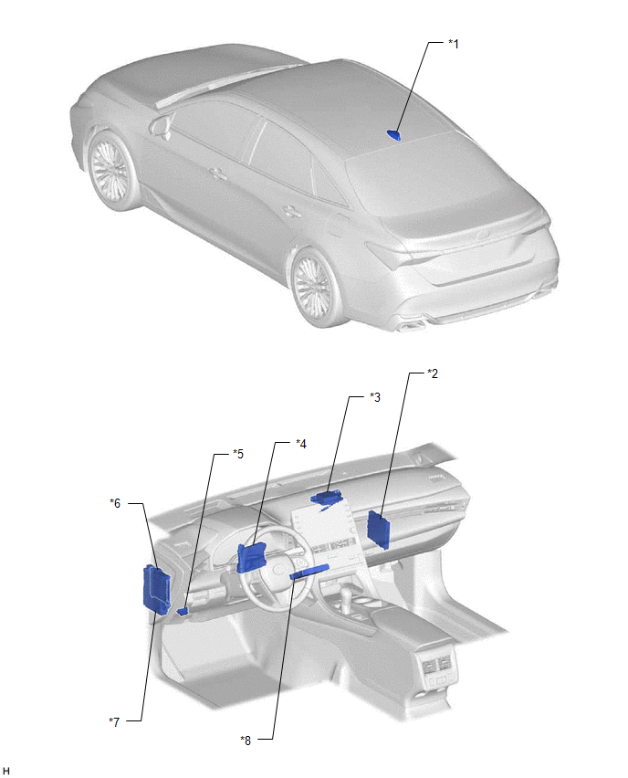
|
*1 | TELEPHONE ANTENNA ASSEMBLY - GPS - Telephone Main |
*2 | CERTIFICATION ECU (SMART KEY ECU ASSEMBLY) |
|
*3 | NAVIGATION ANTENNA ASSEMBLY - Telephone Sub | *4 |
AIR CONDITIONING AMPLIFIER ASSEMBLY |
|
*5 | DLC3 |
*6 | MAIN BODY ECU (MULTIPLEX NETWORK BODY ECU) |
|
*7 | INSTRUMENT PANEL JUNCTION BLOCK ASSEMBLY - DCM FUSE - ECU-IG2 NO. 3 FUSE - ECU-ACC FUSE |
*8 | DCM (TELEMATICS TRANSCEIVER) |
PRECAUTION
PRECAUTION FOR DISCONNECTING CABLE FROM NEGATIVE BATTERY TERMINAL
NOTICE:
When disconnecting the cable from the negative (-) battery terminal, initialize the following systems after the terminal is reconnected.
|
System Name | See Procedure |
|---|---|
|
Lane Departure Alert System (w/ Steering Control) |
|
|
Intelligent Clearance Sonar System | |
|
Parking Assist Monitor System | |
|
Panoramic View Monitor System | |
|
Pre-collision System | |
|
Lighting System (for Gasoline Model with Cornering Light) |
SERVICE MODE
NOTICE:
(a) Service mode
HINT:
To cancel service mode, turn the engine switch off and on (IG) to display the service mode screen and cancel service mode.
(1) Service mode (Using the Techstream)
(2) Service mode (When not using the Techstream)
w/o Navigation System: Click here 
w/ Navigation System: Click here
PRECAUTION FOR TELEMATICS SYSTEM
(a) If replacing any of the following parts, refer to Initialization.
Click here
NOTICE:
If registration is not performed after replacing any of the following parts, the remote door lock and unlock and remote engine start and stop will not be available.
(1) Certification ECU (smart key ECU assembly)
(2) DCM (telematics transceiver)
(3) Main body ECU (multiplex network body ECU)
(b) If an additional device such as a theft deterrent or OBD monitoring device is connected to the DLC3, some functions may not operate correctly.
PROBLEM SYMPTOMS TABLE
HINT:
|
Symptom | Suspected Area |
Link |
|---|---|---|
| Vehicle status cannot be checked using the application |
Proceed to "Remote Service Malfunction" |
|
|
Vehicle status alerts are not received by the application even if remote notification operation conditions are met |
Proceed to "Remote Service Malfunction" |
|
|
Vehicle cannot be operated remotely using the application |
Perform remote door lock and unlock registration and check if the problem symptom recurs |
|
|
Proceed to "Remote Service Malfunction" |
|
|
Symptom | Suspected Area |
Link |
|---|---|---|
| Engine does not start by remote engine start function |
Proceed to "Remote Engine Starter does not Operate" |
|
|
Engine does not stop by remote engine stop function |
Proceed to "Remote Engine Starter does not Operate" |
|
WIRING DIAGRAM
CAUTION / NOTICE / HINT
NOTICE:
Before replacing the DCM (telematics transceiver), refer to Registration.
Click here 
PROCEDURE
| 1. |
CHECK SMART KEY SYSTEM (for Start Function) |
(a) Check that the engine can be started by pressing the engine switch.
|
Result | Proceed to |
|---|---|
|
Engine can be started. |
A |
| Engine cannot be started. |
B |
| B |
 | GO TO SMART KEY SYSTEM (for Start System) |
|
| 2. |
REGISTRATION |
HINT:
If registration is not performed after replacing any of the following parts, the remote engine start and stop will not be available.(a) Perform remote engine start and stop registration.
Click here
(b) Check if the problem symptom recurs.
|
Result | Proceed to |
|---|---|
|
System does not return to normal. |
A |
| System returns to normal. |
B |
| B |
| END |
|
| 3. |
CHECK DTC |
(a) If DTC B2285 is output, perform troubleshooting for DTC B2285 first.
|
Result | Proceed to |
|---|---|
|
DTC B2285 is not output. |
A |
| DTC B2285 is output. |
B |
| B |
| GO TO DTC B2285 |
|
| 4. |
CHECK DCM (TELEMATICS TRANSCEIVER) |
(a) Disconnect the G9 DCM (telematics transceiver) connector.
(b) Measure the voltage according to the value(s) in the table below.
Standard Voltage:
|
Tester Connection | Condition |
Specified Condition |
|---|---|---|
|
G9-29 (SLPD) - Body ground |
Steering locked | 11 to 14 V |
|
Steering unlocked | Below 1.5 V |
HINT:
The steering locks when any door is opened with the shift lever in P and the engine switch off. The steering unlocks when the engine switch is turned on (ACC).
| OK | | REPLACE DCM (TELEMATICS TRANSCEIVER) |
|
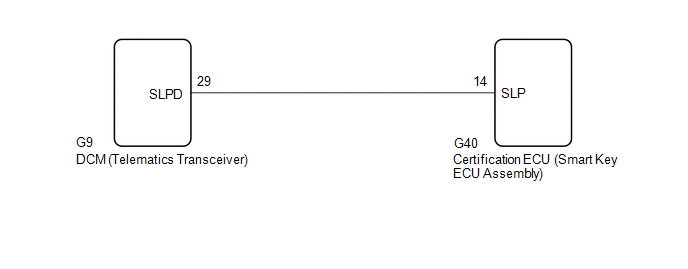
| 5. |
CHECK HARNESS AND CONNECTOR (DCM (TELEMATICS TRANSCEIVER) - CERTIFICATION ECU (SMART KEY ECU ASSEMBLY)) |
(a) Disconnect the G9 DCM (telematics transceiver) connector.
(b) Disconnect the G40 certification ECU (smart key ECU assembly) connector.
(c) Measure the resistance according to the value(s) in the table below.
Standard Resistance:
|
Tester Connection | Condition |
Specified Condition |
|---|---|---|
|
G9-29 (SLPD) - G40-14 (SLP) |
Always | Below 1 Ω |
|
G9-29 (SLPD) or G40-14 (SLP) - Body ground |
Always | 10 kΩ or higher |
| OK | | REPLACE CERTIFICATION ECU (SMART KEY ECU ASSEMBLY) |
| NG | | REPAIR OR REPLACE HARNESS OR CONNECTOR |
PROCEDURE
|
1. | CHECK CAN COMMUNICATION SYSTEM |
(a) Connect the Techstream to the DLC3.
(b) Turn the engine switch on (IG).
(c) Turn the Techstream on.
(d) Enter the following menus: Bus Check.
Click here 
(e) Check that all ECUs and sensors that use CAN communication are connected.
|
Result | Proceed to |
|---|---|
|
There are no connection problems. |
A |
| There is a connection problem. |
B |
| B |
 | GO TO CAN COMMUNICATION SYSTEM |
|
| 2. |
CHECK DTC OUTPUT |
(a) Connect the Techstream to the DLC3.
(b) Turn the engine switch on (IG).
(c) Turn the Techstream on.
(d) Enter the following menus: Health Check.
(e) Check for DTCs.
|
Result | Proceed to |
|---|---|
|
DTCs are not output. |
A |
| DTCs are output. |
B |
| B |
| INSPECT EACH ECU SYSTEM |
|
| 3. |
CHECK OPERATION OF EACH SYSTEM |
(a) Check that each system related to Toyota Entune Remote Connect operates normally.
(1) Check power door lock control system
Click here
(2) Check smart key system (for Entry Function)
Click here
(3) Check smart key system (for Start Function)
Click here
(4) Check theft deterrent system
Click here
(5) Check lighting system (INT)
Click here
(6) Check meter/gauge system
Click here
(7) Check air conditioning system (for Automatic Air Conditioning System)
Click here
(8) Check power window control system
Click here
(9) Check sliding roof system
Click here
(10) Check lighting system (EXT)
Click here
|
Result | Proceed to |
|---|---|
|
All of the systems related to Toyota Entune Remote Connect operate normally. |
A |
| Any system related to Toyota Entune Remote Connect does not operate normally. |
B |
| B |
| GO TO ABNORMAL SYSTEM |
|
| 4. |
CHECK DCM OPERATION HISTORY |
(a) Check DCM Operation History.
Body Electrical > Telematics > Utility|
Tester Display |
|---|
| DCM Operation History |
| NEXT | | CONTACT SERVICE CENTER |
SYSTEM DESCRIPTION
OUTLINE
(a) Toyota Entune Remote Connect, which enables the user to check the vehicle status and operate the vehicle from a remote location, has been adopted.
(b) Toyota Entune Remote Connect is available by installing a dedicated smartphone application after entering a service contract*.
(c) Toyota Entune Remote Connect services are performed through data communication between mainly a Toyota Entune Remote Connect capable DCM (telematics transceiver), the service center and a smartphone with the application installed.
HINT:
FUNCTION OF MAIN COMPONENTS
|
Component | Function | |
|---|---|---|
|
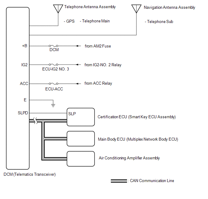
DCM (Telematics Transceiver) |
| |
| Telephone Antenna Assembly |
GPS Antenna | Receives signals from GPS satellites and transmits these signals to the DCM (telematics transceiver). |
|
Telephone Antenna (Main) | Transmits signals from the DCM (telematics transceiver) and receives signals from the service center. | |
|
Navigation Antenna Assembly |
Telephone Antenna (Sub) |
Receives signals from the service center. |
|
Certification ECU (Smart key ECU assembly) |
Receives the remote engine start and stop signal from the user's smartphone or electrical key transmitter sub-assembly via the DCM (telematics transceiver) and initiates the engine start operation. | |
|
Air Conditioning Amplifier Assembly |
| |
| Main Body ECU (Multiplex Network Body ECU) |
Locks the door when a remote door lock and unlock operation signal is received. | |
FUNCTION
(a) The main services of Toyota Entune Remote Connect are as follows:
|
Category | Remote Service |
Function |
|---|---|---|
| Remote Information |
Vehicle Status Report | Allows the vehicle status (doors open/closed, etc.) and vehicle information (distance traveled, etc.) to be checked from a remote location via a smartphone, after the engine switch has been turned off. By updating the information, the latest vehicle status can be displayed.*1 |
|
Remote Notification | Guest Driver Monitor |
|
| Vehicle Status Alerts |
Sends a notification to the user if certain operations are not performed within a certain amount of time after the engine switch is turned off, such as locking the doors, closing the windows, etc.*2*4 | |
|
Remote Operation | Remote Engine Start and Stop |
|
| Remote Door Lock and Unlock |
Allows the doors to be locked/unlocked from a remote location via a smartphone.*7 |
|
Ambient Temperature |
Air Conditioning System |
Rear Defogger |
|---|---|---|
|
30°C (86°F) or higher |
○ (Temperature setting: 25°C (77°F)) |
- |
|
Below 5°C (41°F) |
○ |
SYSTEM DIAGRAM
TERMINALS OF ECU
HINT:
Check from the rear of the connector while it is connected to the components.
DCM (TELEMATICS TRANSCEIVER)
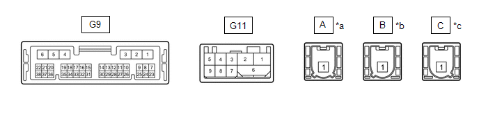
|
*a | to Telephone Antenna (Sub) |
*b | to Telephone Antenna (Main) |
|
*c | to GPS Antenna |
- | - |
|
Terminal No. (Symbol) | Wiring Color |
Terminal Description | Condition |
Specified Condition |
|---|---|---|---|---|
|
G9-1 (+B) - G9-4 (E) |
B - W-B | Power source (+B) |
Always | 11 to 14 V |
|
G9-4 (E) - Body ground |
W-B - Body ground | Ground |
Always | Below 1 V |
|
G9-7 (IG2) - G9-4 (E) |
LG - W-B |
Power source (IG) | Engine switch on (IG) |
11 to 14 V |
|
Engine switch off | Below 1 V | |||
|
G9-8 (ACC) - G9-4 (E) |
B- W-B | Power source (ACC) |
Engine switch on (ACC) |
11 to 14 V |
|
Engine switch off | Below 1 V | |||
|
G9-15 (CANP) | R |
CAN communication signal |
- | - |
|
G9-16 (CANN) | W |
CAN communication signal |
- | - |
|
G9-29 (SLPD) - G9-4 (E) |
L - W-B | Steering lock bar position signal |
Steering locked | 11 to 14 V |
|
Steering unlocked | Below 1.5 V | |||
|
G11-1 (USB-) | GR |
USB communication line |
- | - |
|
G11-2 (USB+) | GR |
USB communication line |
- | - |
|
G11-6 (USBS) - Body ground |
Shielded - Body ground |
Shield ground | Always |
Below 1 Ω |
|
G11-3 (USBG) - Body ground |
GR - Body ground | DCM (Telematics Transceiver) power supply ground signal |
Always | Below 1 Ω |
CERTIFICATION ECU (SMART KEY ECU ASSEMBLY)
Click here

DESCRIPTION
These DTCs are stored when a malfunction occurs in the CAN communication circuit.
HINT:
If CAN communication system DTCs are stored, they may also be stored for other systems.
|
DTC No. | Detection Item |
DTC Detection Condition | Trouble Area |
|---|---|---|---|
|
U0142 | Lost Communication with Body Control Module "B" |
Lost communication with main body ECU (multiplex network body ECU) |
CAN communication system |
|
U0155 | Lost Communication with Instrument Panel Cluster (IPC) Control Module |
Lost communication with combination meter assembly |
CAN communication system |
|
U0163 | Lost Communication with Navigation Control Module |
Lost communication with radio and display receiver assembly |
CAN communication system |
PROCEDURE
| 1. |
CHECK DTC |
(a) Clear the DTCs.
Body Electrical > Telematics > Clear DTCs(b) Recheck for DTCs and check if the same DTC is output again.
Body Electrical > Telematics > Trouble Codes|
Result | Proceed to |
|---|---|
|
DTCs are output. | A |
|
DTCs are not output. |
B |
HINT:
Click here 
| A |  | GO TO CAN COMMUNICATION SYSTEM |
| B |
| USE SIMULATION METHOD TO CHECK |
Toyota Avalon (XX50) 2019-2022 Service & Repair Manual > Front Suspension: Front Shock Absorber
Components COMPONENTS ILLUSTRATION *A w/o AVS - - *1 FRONT SHOCK ABSORBER WITH COIL SPRING *2 FRONT SPEED SENSOR *3 FRONT STABILIZER LINK ASSEMBLY *4 FRONT FLEXIBLE HOSE *5 STEERING KNUCKLE - - Tightening torque for "Major areas involving basic vehicle performance such as moving/turning/stopping": N ...


