COMPONENTS
ILLUSTRATION
|
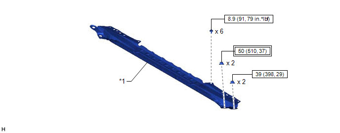
*1 | FRONT CENTER UPPER SUSPENSION BRACE SUB-ASSEMBLY |
- | - |
 |
Tightening torque for "Major areas involving basic vehicle performance such as moving/turning/stopping": N*m (kgf*cm, ft.*lbf) |
 |
N*m (kgf*cm, ft.*lbf): Specified torque |
ILLUSTRATION
|
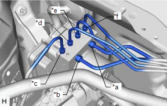
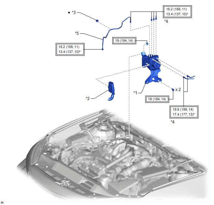
*1 | BRAKE ACTUATOR WITH BRACKET |
*2 | CONNECTOR |
|
*3 | BRAKE TUBE CLAMP |
*4 | BRAKE LINE |
|
*5 | FRONT NO. 3 BRAKE TUBE |
- | - |
|
|
Tightening torque for "Major areas involving basic vehicle performance such as moving/turning/stopping": N*m (kgf*cm, ft.*lbf) |
* | For use with a union nut wrench |
|
● | Non-reusable part |
- | - |
ILLUSTRATION
|
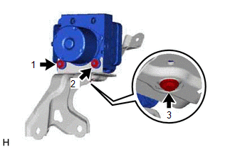
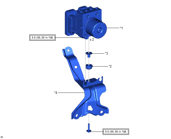
*1 | BRAKE ACTUATOR ASSEMBLY |
*2 | BRAKE ACTUATOR BOLT CUSHION |
|
*3 | NO. 1 BRAKE ACTUATOR CASE COLLAR |
*4 | BRAKE ACTUATOR BRACKET ASSEMBLY |
|
|
Tightening torque for "Major areas involving basic vehicle performance such as moving/turning/stopping" : N*m (kgf*cm, ft.*lbf) |
- | - |
INSTALLATION
CAUTION / NOTICE / HINT
HINT:
The parking brake indicator light blinks (red) when the engine switch is turned to ON after replacing the brake actuator assembly. Operate the electric parking brake switch assembly to turn off the parking brake indicator light.
PROCEDURE
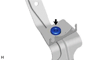
1. INSTALL BRAKE ACTUATOR BOLT CUSHION
(a) Install the brake actuator bolt cushion to the brake actuator bracket assembly.
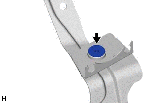
2. INSTALL NO. 1 BRAKE ACTUATOR CASE COLLAR
(a) Install the No. 1 brake actuator case collar to the brake actuator bracket cushion.
NOTICE:
Make sure that the No. 1 brake actuator case collar is in full contact with the brake actuator bracket cushion.
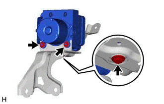
3. INSTALL BRAKE ACTUATOR ASSEMBLY
(a) Install the brake actuator assembly to the brake actuator bracket assembly.
| (b) Tighten the 2 nuts and install the bolt. Torque: 6.5 N·m {66 kgf·cm, 58 in·lbf} NOTICE:
|
|
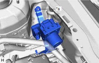
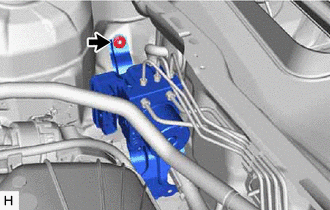
4. INSTALL BRAKE ACTUATOR WITH BRACKET
| (a) Temporarily install the brake actuator with bracket to the vehicle body. NOTICE:
HINT: Install the brake actuator with bracket while avoiding the brake lines. |
|
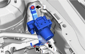
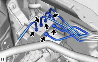
| (b) Install the 2 bolts and nut in the order shown in the illustration. Torque: 19 N·m {194 kgf·cm, 14 ft·lbf} HINT: Install the 2 bolts from the bottom of the vehicle. |
|
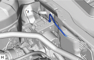
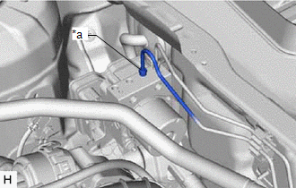
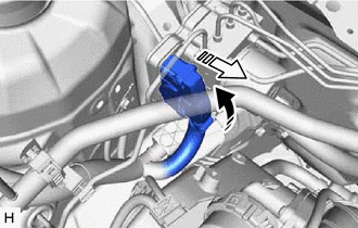
(c) Remove the protective tape.
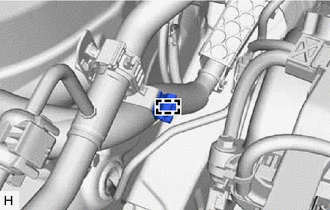
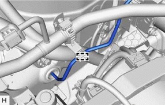
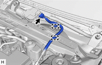
| (d) Engage the clamp to install a new brake tube clamp. |
|
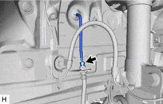
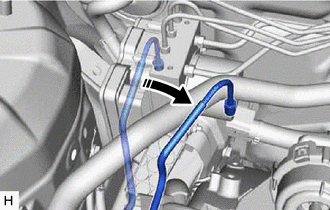
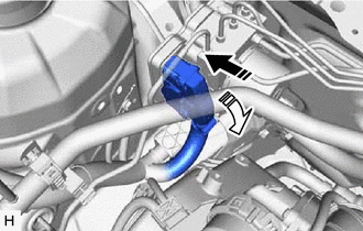
(e) Return the front No. 3 brake tube to its original position.
NOTICE:
Do not apply excessive force to the front No. 3 brake tube.
| (f) Temporarily install the front No. 3 brake tube to the front flexible hose. NOTICE:
|
|
| (g) Engage the clamp to connect the front No. 3 brake tube. NOTICE: Do not kink or damage the front No. 3 brake tube. |
|
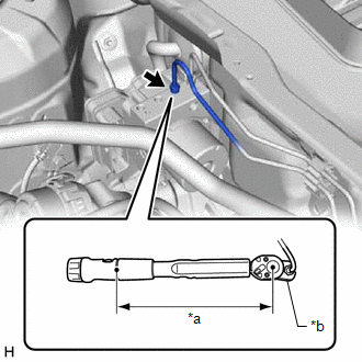
| (h) Temporarily tighten the brake line to the correct position on the brake actuator assembly as shown in the illustration. NOTICE:
|
|
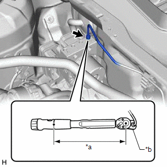
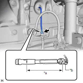
| (i) Using a union nut wrench, fully tighten the brake line. Torque: Specified tightening torque : 15.2 N·m {155 kgf·cm, 11 ft·lbf} NOTICE: Do not kink or damage the brake line. HINT:
|
|
| (j) Temporarily tighten the brake line to the correct position on the brake actuator assembly as shown in the illustration. NOTICE:
|
|
| (k) Using a union nut wrench, fully tighten the brake line. Torque: Specified tightening torque : 15.2 N·m {155 kgf·cm, 11 ft·lbf} NOTICE: Do not kink or damage the brake line. HINT:
|
|
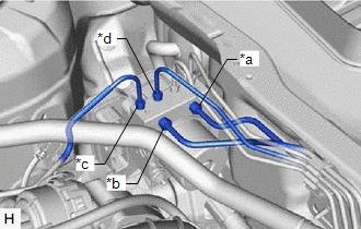
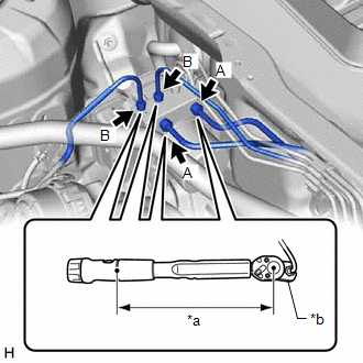
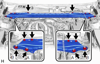
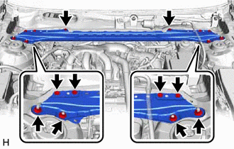
| (l) Temporarily tighten the 4 brake lines to the correct positions on the brake actuator assembly as shown in the illustration. NOTICE:
|
|
| (m) Using a union nut wrench, fully tighten each brake line. Torque: Specified tightening torque (A) : 19.5 N·m {199 kgf·cm, 14 ft·lbf} Specified tightening torque (B) : 15.2 N·m {155 kgf·cm, 11 ft·lbf} NOTICE: Do not kink or damage the brake lines. HINT:
|
|
| (n) Using a union nut wrench, fully tighten the front No. 3 brake tube while holding the front flexible hose with a wrench. Torque: Specified tightening torque : 15.2 N·m {155 kgf·cm, 11 ft·lbf} NOTICE: Do not kink or damage the front No. 3 brake tube. HINT:
|
|
(o) Connect the connector to the brake actuator assembly and lock the lock lever.
 | Connect the connector |
 |
Lock the lock lever |
NOTICE:
5. INSTALL FRONT CENTER UPPER SUSPENSION BRACE SUB-ASSEMBLY
| (a) Temporarily install the front center upper suspension brace sub-assembly with the 6 bolts and 4 nuts. |
|
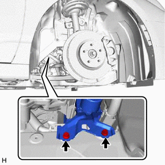
(b) Fully tighten the 2 nuts (A).
Torque:
50 N·m {510 kgf·cm, 37 ft·lbf}
(c) Fully tighten the 6 bolts and 2 nuts (B) to install the front center upper suspension brace sub-assembly.
Torque:
Bolt :
8.9 N·m {91 kgf·cm, 79 in·lbf}
Nut (B) :
39 N·m {398 kgf·cm, 29 ft·lbf}
(d) Engage the 2 clamps to install the wire harness.
(e) Connect the connector.
6. INSTALL COWL TOP VENTILATOR LOUVER SUB-ASSEMBLY
Click here 
7. INSTALL FRONT WHEEL RH
Click here
8. CONNECT CABLE TO NEGATIVE BATTERY TERMINAL
Click here
NOTICE:
When disconnecting the cable, some systems need to be initialized after the cable is reconnected.
Click here
9. BLEED BRAKE SYSTEM
Click here
10. PERFORM SYSTEM VARIANT LEARNING AND ACCELERATION SENSOR ZERO POINT CALIBRATION
Click here
11. PERFORM TEST MODE INSPECTION
Click here
12. INSPECT BRAKE ACTUATOR USING TECHSTREAM
Click here
13. CHECK FOR AND CLEAR DTCS
Click here
ON-VEHICLE INSPECTION
PROCEDURE
1. CONNECT TECHSTREAM
(a) Connect the Techstream to the DLC3 with the ignition switch off.
(b) Start the engine and run it at idle.
(c) Turn the Techstream on.
(d) Enter the following menus: Chassis / ABS/VSC/TRAC/EPB / Active Test.
HINT:
Refer to the Techstream operator's manual for further details.
2. INSPECT ACTUATOR MOTOR OPERATION
(a) Enter the following menus: Chassis / ABS/VSC/TRAC / Active Test / Motor Relay.
Chassis > ABS/VSC/TRAC > Active Test|
Tester Display |
|---|
| Motor Relay |
(b) Turn the motor relay on and check for actuator motor operation sounds.
NOTICE:
Do not keep the motor relay on continuously for more than 5 seconds. If it needs to be operated repeatedly, wait an interval of more than 20 seconds between operations.
(c) Turn the motor relay off.
(d) Fully depress the brake pedal and hold it for approximately 15 seconds. Check that the initial brake pedal depth is maintained for the entire 15 seconds.
(e) Turn the motor relay on and check that the brake pedal does not pulsate.
NOTICE:
Do not keep the motor relay on continuously for more than 5 seconds. If it needs to be operated repeatedly, wait an interval of more than 20 seconds between operations.
(f) Turn the motor relay off and release the brake pedal.
3. INSPECT FRONT RIGHT WHEEL OPERATION
(a) Enter the following menus: Chassis / ABS/VSC/TRAC / Active Test / ABS Solenoid.
Chassis > ABS/VSC/TRAC > Active Test|
Tester Display |
|---|
| ABS Solenoid |
(b) Depress the brake pedal and hold it.
NOTICE:
Do not turn on a solenoid in a manner different than that shown in the following steps.
(c) Turn the SFRH and SFRR solenoids on simultaneously and check that the brake pedal cannot be depressed further.
NOTICE:
Each solenoid operates for 2 seconds and turns off automatically. If a solenoid needs to be operated repeatedly, wait an interval of more than 20 seconds between operations.
(d) Turn the SFRH and SFRR solenoids off simultaneously and check that the brake pedal can be depressed.
(e) With the brake pedal still depressed, turn the motor relay on and check that the brake pedal rises.
Chassis > ABS/VSC/TRAC > Active Test|
Tester Display |
|---|
| Motor Relay |
NOTICE:
Do not keep the motor relay on continuously for more than 5 seconds. If it needs to be operated repeatedly, wait an interval of more than 20 seconds between operations.
(f) Turn the motor relay off and release the brake pedal.
4. INSPECT OTHER WHEEL OPERATION
(a) Using the same procedure, check the solenoids for the other wheels.
HINT:
REMOVAL
CAUTION / NOTICE / HINT
The necessary procedures (adjustment, calibration, initialization or registration) that must be performed after parts are removed and installed, or replaced during brake actuator assembly removal/installation are shown below.
Necessary Procedures After Parts Removed/Installed/Replaced|
Replaced Part or Performed Procedure |
Necessary Procedure | Effect/Inoperative Function when Necessary Procedure not Performed |
Link |
|---|---|---|---|
|
*: When performing learning using the Techstream.
Click here | |||
|
Battery terminal is disconnected/reconnected |
Perform steering sensor zero point calibration |
Lane departure alert system (w/ Steering Control) |
|
|
Pre-collision system | |||
|
Intelligent Clearance Sonar System* | |||
|
Lighting System (for Gasoline Model with Cornering Light) | |||
|
Memorize steering angle neutral point |
Parking assist monitor system |
| |
|
Panoramic View Monitor System |
| ||
|
Replacement of brake actuator assembly |
Perform system variant learning and acceleration sensor zero point calibration |
|
|
|
Operate the electric parking brake switch (electric parking brake switch assembly) |
Parking brake indicator light blinks when the engine switch is first turned on (IG) |
| |
PROCEDURE
1. PRECAUTION
NOTICE:
After turning the engine switch off, waiting time may be required before disconnecting the cable from the negative (-) battery terminal. Therefore, make sure to read the disconnecting the cable from the negative (-) battery terminal notices before proceeding with work.
Click here

2. DISCONNECT CABLE FROM NEGATIVE BATTERY TERMINAL
Click here
NOTICE:
When disconnecting the cable, some systems need to be initialized after the cable is reconnected.
Click here
3. DRAIN BRAKE FLUID
NOTICE:
If brake fluid leaks onto any painted surface, immediately wash it off.
4. REMOVE FRONT WHEEL RH
Click here
5. REMOVE COWL TOP VENTILATOR LOUVER SUB-ASSEMBLY
Click here
6. REMOVE FRONT CENTER UPPER SUSPENSION BRACE SUB-ASSEMBLY
| (a) Disconnect the connector. |
|
(b) Disengage the 2 clamps and separate the wire harness.
| (c) Remove the 6 bolts, 4 nuts and front center upper suspension brace sub-assembly. |
|
7. REMOVE BRAKE ACTUATOR WITH BRACKET
(a) Release the lock lever and disconnect the connector from the brake actuator assembly.
 | Release the lock lever |
 |
Disconnect the connector |
NOTICE:
Be careful not to allow any brake fluid to enter the connector.
| (b) Use tags or make a memo to identify the places to reconnect the brake lines. |
|
| (c) Using a union nut wrench, disconnect the 6 brake lines from the brake actuator assembly. NOTICE:
|
|
| (d) Using a union nut wrench, disconnect the front No. 3 brake tube while holding the front flexible hose with a wrench. NOTICE:
|
|
| (e) Disengage the clamp and separate the front No. 3 brake tube. NOTICE: Do not kink or damage the front No. 3 brake tube. |
|
| (f) Move aside the front No. 3 brake tube as shown in the illustration. NOTICE: Do not apply excessive force to the front No. 3 brake tube. |
|
| (g) Disengage the clamp and remove the brake tube clamp. |
|
(h) Apply protective tape to the vehicle body as shown in the illustration.
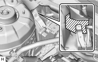
 |
Protective Tape |
| (i) Remove the 2 bolts. HINT: Insert the tool from the bottom of the vehicle. |
|
| (j) Remove the nut and brake actuator with bracket. NOTICE:
HINT: Remove the brake actuator with bracket while avoiding the brake lines. |
|
8. REMOVE BRAKE ACTUATOR ASSEMBLY
| (a) Loosen the 2 nuts. |
|
(b) Remove the bolt and brake actuator assembly from the brake actuator bracket assembly.
NOTICE:
9. REMOVE NO. 1 BRAKE ACTUATOR CASE COLLAR
| (a) Remove the No. 1 brake actuator case collar from the brake actuator bracket cushion. |
|
10. REMOVE BRAKE ACTUATOR BOLT CUSHION
| (a) Remove the brake actuator bolt cushion from the brake actuator bracket assembly. |
|
Toyota Avalon (XX50) 2019-2022 Service & Repair Manual > Exterior Panels / Trim: Black Out Tape(for Rear Door)
Components COMPONENTS ILLUSTRATION *A for HV Model - - *1 LUGGAGE TRIM SERVICE HOLE COVER - - ILLUSTRATION *1 REAR DOOR ARMREST COVER SUB-ASSEMBLY *2 REAR DOOR TRIM ASSEMBLY COVER *3 REAR DOOR TRIM BOARD SUB-ASSEMBLY *4 REAR POWER WINDOW REGULATOR SWITCH ASSEMBLY WITH REAR DOOR UPPER ARMREST BASE PA ...