COMPONENTS
ILLUSTRATION
|
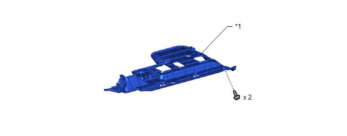
*1 | NO. 1 INSTRUMENT PANEL UNDER COVER SUB-ASSEMBLY |
- | - |
ILLUSTRATION
|
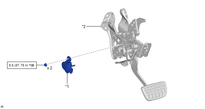
*1 | BRAKE PEDAL STROKE SENSOR ASSEMBLY |
*2 | BRAKE PEDAL SUPPORT ASSEMBLY |
 |
N*m (kgf*cm, ft.*lbf): Specified torque |
- | - |
INSTALLATION
PROCEDURE
1. INSPECT AND ADJUST BRAKE PEDAL HEIGHT
Click here 
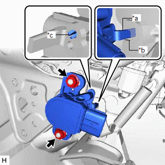
2. INSTALL BRAKE PEDAL STROKE SENSOR ASSEMBLY
NOTICE:
(a) When installing a new brake pedal stroke sensor assembly:
NOTICE:
Do not break the brake pedal stroke sensor assembly lever set pin before installing the brake pedal stroke sensor assembly with the 2 nuts.
| (1) Install a new brake pedal stroke sensor assembly to the brake pedal support assembly with the 2 nuts. Torque: 8.5 N·m {87 kgf·cm, 75 in·lbf} NOTICE:
|
|
(2) Connect the connector.
(3) Firmly depress the brake pedal to break the brake pedal stroke sensor assembly lever set pin.
(4) Remove the broken lever set pin.
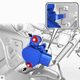
(b) When reusing the brake pedal stroke sensor assembly:
| (1) Install the brake pedal stroke sensor assembly to the brake pedal support assembly and temporarily tighten the 2 nuts. NOTICE:
|
|
(2) Connect the connector.
3. CONNECT CABLE TO NEGATIVE AUXILIARY BATTERY TERMINAL
Click here
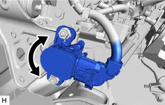
4. ADJUST BRAKE PEDAL STROKE SENSOR ASSEMBLY
NOTICE:
When the brake pedal stroke sensor assembly is being reused, perform the following procedure to adjust it.
(a) Connect the Techstream to the DLC3 with the power switch off.
(b) Turn the power switch on (IG).
(c) Turn the Techstream on.
(d) Enter the following menus: Chassis / ABS/VSC/TRAC / Data List / Stroke Sensor.
Chassis > ABS/VSC/TRAC > Data List|
Tester Display |
|---|
| Stroke Sensor |
| (e) Read the stroke sensor value in the Data List, and turn the brake pedal stroke sensor assembly slowly to the right or left to adjust the output voltage so that it is within the following range. Standard Voltage (without the brake pedal depressed): 0.8 to 1.2 V |
|
(f) Tighten the 2 nuts.
Torque:
8.5 N·m {87 kgf·cm, 75 in·lbf}
NOTICE:
Do not depress the brake pedal after turning the power switch on (IG).
(g) Turn the Techstream off and turn the power switch off.
(h) Disconnect the Techstream from the DLC3.
5. INSTALL NO. 1 INSTRUMENT PANEL UNDER COVER SUB-ASSEMBLY
Click here
6. PERFORM INITIALIZATION AND CALIBRATION
Perform linear solenoid valve offset learning, ABS holding solenoid valve learning, brake pedal stroke sensor assembly zero point calibration and system information memorization:
Click here
7. CHECK AND CLEAR DTC
Click here
REMOVAL
CAUTION / NOTICE / HINT
The necessary procedures (adjustment, calibration, initialization, or registration) that must be performed after parts are removed, installed, or replaced during brake pedal stroke sensor assembly removal/installation are shown below.
Necessary Procedures After Parts Removed/Installed/Replaced|
Replaced Part or Performed Procedure |
Necessary Procedure | Effect/Inoperative Function when Necessary Procedure not Performed |
Link |
|---|---|---|---|
|
*: When performing learning using the Techstream.
Click here | |||
|
Auxiliary battery terminal is disconnected/reconnected |
Perform steering sensor zero point calibration |
Lane Departure Alert System (w/ Steering Control) |
|
|
Pre-collision System | |||
|
Intelligent Clearance Sonar System* | |||
|
Lighting System (for HV Model with Cornering Light) | |||
|
Memorize steering angle neutral point |
Parking Assist Monitor System |
| |
|
Panoramic View Monitor System |
| ||
|
Replacement of brake pedal stroke sensor assembly |
|
| for Initialization
for Calibration:
|
NOTICE:
While the auxiliary battery is connected, even if the power switch is off, the brake control system activates when the brake pedal is depressed or any door courtesy switch turns on. Therefore, when servicing the brake system components, do not operate the brake pedal or open/close the doors while the auxiliary battery is connected.
PROCEDURE
1. PRECAUTION
NOTICE:
After turning the power switch off, waiting time may be required before disconnecting the cable from the negative (-) auxiliary battery terminal. Therefore, make sure to read the disconnecting the cable from the negative (-) auxiliary battery terminal notices before proceeding with work.
Click here 
2. DISCONNECT CABLE FROM NEGATIVE AUXILIARY BATTERY TERMINAL
Click here
3. REMOVE NO. 1 INSTRUMENT PANEL UNDER COVER SUB-ASSEMBLY
Click here
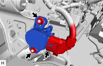
4. REMOVE BRAKE PEDAL STROKE SENSOR ASSEMBLY
| (a) Disconnect the connector from the brake pedal stroke sensor assembly. |
|
(b) Remove the 2 nuts and brake pedal stroke sensor assembly from the brake pedal support assembly.
NOTICE:
Toyota Avalon (XX50) 2019-2022 Service & Repair Manual > Audio And Visual System(for Gasoline Model): Radio Receiver Power Source Circuit. Registered Device cannot be Deleted. Reverse Signal Circuit
Radio Receiver Power Source Circuit DESCRIPTION This is the power source circuit to operate the radio and display receiver assembly. WIRING DIAGRAM CAUTION / NOTICE / HINT NOTICE: Inspect the fuses for circuits related to this system before performing the following procedure. PROCEDURE 1. CHECK HARN ...