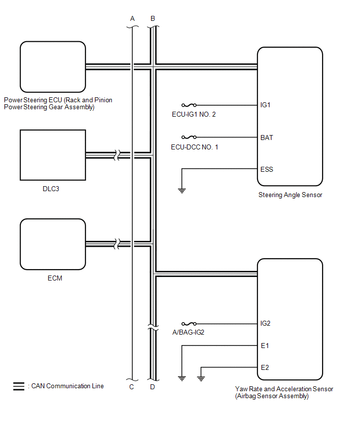
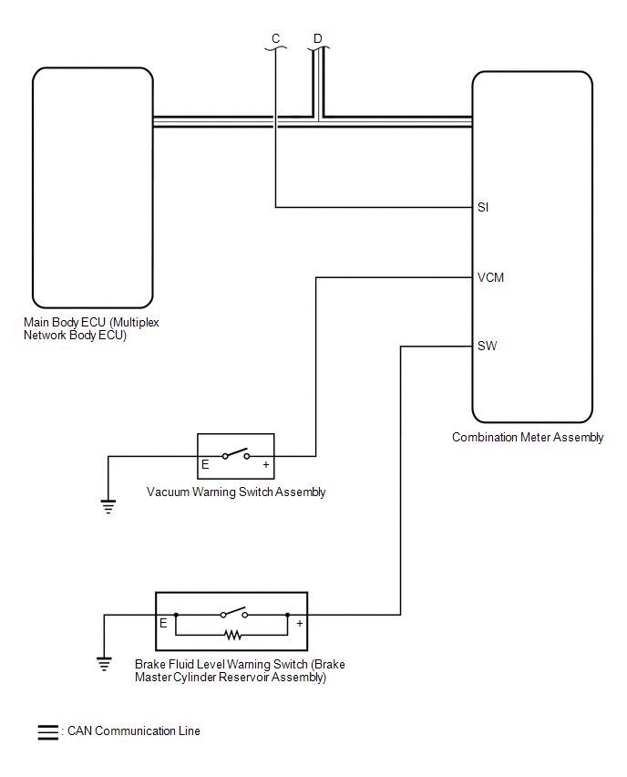
SYSTEM DIAGRAM
|
Transmitting ECU (Transmitter) |
Receiving ECU | Signal |
Communication Method |
|---|---|---|---|
|
Skid control ECU (brake actuator assembly) |
Steering angle sensor | Steering angle sensor request signal |
CAN communication line |
|
Steering angle sensor |
Skid control ECU (brake actuator assembly) |
Steering angle sensor signal |
CAN communication line |
|
Skid control ECU (brake actuator assembly) |
Yaw rate and acceleration sensor (airbag sensor assembly) |
Yaw rate and acceleration request signal |
CAN communication line |
|
Yaw rate and acceleration sensor (airbag sensor assembly) |
Skid control ECU (brake actuator assembly) |
Yaw rate and acceleration signal |
CAN communication line |
|
Skid control ECU (brake actuator assembly) |
ECM |
| CAN communication line |
|
ECM | Skid control ECU (brake actuator assembly) |
| CAN communication line |
|
Skid control ECU (brake actuator assembly) |
Power steering ECU (rack and pinion power steering gear assembly) |
| CAN communication line |
|
Main body ECU (multiplex network body ECU) |
Skid control ECU (brake actuator assembly) |
| CAN communication line |
|
Skid control ECU (brake actuator assembly) |
Combination meter assembly |
| CAN communication line |
|
Airbag sensor assembly |
Skid control ECU (brake actuator assembly) |
Secondary collision brake request signal |
CAN communication line |
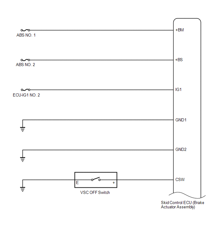
TERMINALS OF ECU
TERMINALS OF ECU

|
*a | Component without harness connected (Skid Control ECU (Brake Actuator Assembly)) |
- | - |
|
Terminal No. (Symbol) | Terminal Description |
|---|---|
|
1 (+BM) | ABS motor relay power supply |
|
2 | - |
|
3 | - |
|
4 | - |
|
5 (CANH) | CAN communication line H |
|
6 (CSW) | VSC OFF switch input |
|
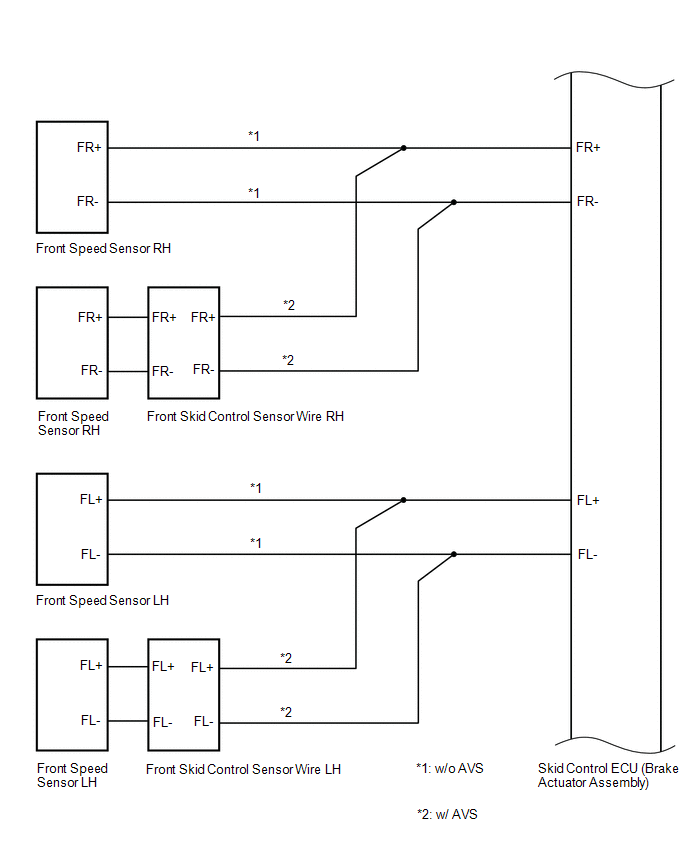
7 (FL-) | Front wheel speed LH (-) signal input |
|
8 | - |
|
9 | - |
|
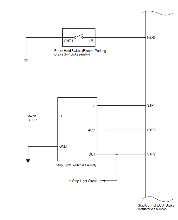
10 (STPO) | Stop light control relay (stop light switch assembly) output |
|
11 | - |
|
12 | - |
|
13 | - |
|
14 (GND2) | Pump motor ground |
|
15 | - |
|
16 | - |
|
17 | - |
|
18 | - |
|
19 (CANL) | CAN communication line L |
|
20 | - |
|
21 (FR+) | Front wheel speed RH (+) signal input |
|
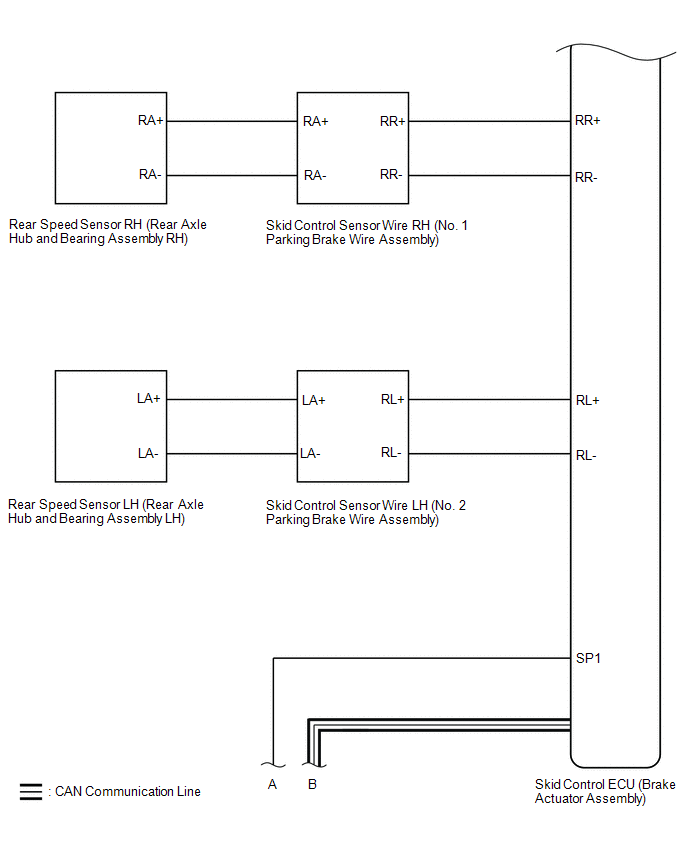
22 (RR+) | Rear wheel speed RH (+) signal input |
|
23 (RL-) | Rear wheel speed LH (-) signal input |
|
24 (FL+) | Front wheel speed LH (+) signal input |
|
25 | - |
|
26 (FR-) | Front wheel speed RH (-) signal input |
|
27 | - |
|
28 | - |
|
29 | - |
|
30 (+BS) | ABS solenoid relay power supply |
|
31 | - |
|
32 | - |
|
33 | - |
|
34 (SP1) | Speed signal output for speedometer |
|
35 | - |
|
36 (IG1) | IG1 power source input |
|
37 (RR-) | Rear wheel speed RH (-) signal input |
|
38 | - |
|
39 (RL+) | Rear wheel speed LH (+) signal input |
|
40 | - |
|
41 | - |
|
42 (STP) | Stop light switch assembly input |
|
43 (HZRI) | Brake hold switch (electric parking brake switch assembly) input |
|
44 (STP2) | Stop light control relay (stop light switch assembly) input |
|
45 | - |
|
46 (GND1) | Skid control ECU (brake actuator assembly) ground |
TERMINAL INSPECTION
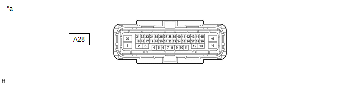
(a) Disconnect the connector and measure the voltage and resistance on the wire harness side.
|
*a | Front view of wire harness connector (to Skid Control ECU (Brake Actuator Assembly)) |
- | - |
HINT:
The voltage cannot be measured with the connector connected to the skid control ECU (brake actuator assembly) because the connector is watertight.
Standard|
Terminal No. (Symbol) | Wiring Color |
Terminal Description | Condition |
Specified Condition |
|---|---|---|---|---|
|
A28-1 (+BM) - Body ground |
B - Body ground | ABS motor relay power supply |
Always | 11 to 14 V |
|
A28-6 (CSW) - Body ground |
P - Body ground | VSC OFF switch input |
VSC OFF switch on → off (Pressed → not pressed) |
Below 1 Ω → 10 kΩ or higher |
|
A28-10 (STPO) - Body ground |
L - Body ground | Stop light control relay (stop light switch assembly) output |
Always | 11 to 14 V |
|
A28-14 (GND2) - Body ground |
W-B - Body ground | Pump motor ground |
Always | Below 1 Ω |
|
A28-30 (+BS) - Body ground |
G - Body ground | ABS solenoid relay power supply |
Always | 11 to 14 V |
|
A28-36 (IG1) - Body ground |
B - Body ground | IG1 power source input |
Engine switch on (IG) |
11 to 14 V |
|
A28-42 (STP) - Body ground |
GR - Body ground | Stop light switch assembly input |
Stop light switch assembly on → off (Brake pedal depressed → released) |
(+BS x 0.85) to 14 V* → Below 1.5 V |
|
A28-43 (HZRI) - Body ground |
LG - Body ground | Brake hold switch (electric parking brake switch assembly) input |
Brake hold switch (electric parking brake switch assembly) on → off (Pressed → not pressed) |
Below 1 Ω → 10 kΩ or higher |
|
A28-44 (STP2) - Body ground |
R - Body ground | Stop light control relay (stop light switch assembly) input |
Stop light switch assembly on → off (Brake pedal depressed → released) |
(+BS x 0.85) to 14 V* → Below 1.5 V |
|
A28-46 (GND1) - Body ground |
W-B - Body ground | Skid control ECU (brake actuator assembly) ground |
Always | Below 1 Ω |
HINT:
*: The minimum voltage value varies depending on the +BS terminal voltage value. The minimum voltage is 85% or more of the +BS terminal voltage.
TEST MODE PROCEDURE
WARNING LIGHT AND INDICATOR LIGHT INITIAL CHECK
(a) When the engine switch is turned on (IG), check that the ABS warning light, brake system warning light (red indicator), VSC OFF indicator light, brake hold standby indicator light, brake hold operated indicator light and slip indicator light come on for approximately 3 seconds.
HINT:
|
Trouble Area | See Procedure |
|---|---|
|
ABS warning light circuit (Remains on) |
|
|
ABS warning light circuit (Does not come on) |
|
|
Brake system warning light (red indicator) circuit (Remains on) |
|
|
Brake system warning light (red indicator) circuit (Does not come on) |
|
|
VSC OFF indicator light circuit (Remains on) |
|
|
VSC OFF indicator light circuit (Does not come on) |
|
|
Slip indicator light circuit (Remains on) |
|
|
Slip indicator light circuit (Does not come on) |
|
|
Brake hold standby indicator light circuit |
|
|
Brake hold operated indicator light circuit |
|
SENSOR CHECK USING TEST MODE (SIGNAL CHECK) (When Using TECHSTREAM)
NOTICE:
Perform Test Mode (Signal Check) with the vehicle stopped.
HINT:
(a) Procedure to enter Test Mode (Signal Check)
(1) Turn the engine switch off.
(2) Check that the steering wheel is centered.
(3) Check that the shift lever is in P.
(4) Connect the Techstream to the DLC3.
(5) Turn the engine switch on (IG).
(6) Turn the Techstream on.
(7) Switch the skid control ECU (brake actuator assembly) to Test Mode (Signal Check) using the Techstream. Enter the following menus: Chassis / ABS/VSC/TRAC/EPB / Utility / Signal Check.
Chassis > ABS/VSC/TRAC/EPB > Utility|
Tester Display |
|---|
| Signal Check |
HINT:
Do not exit Test Mode (Signal Check) within 5 seconds of entering Test Mode (Signal Check). If Test Mode (Signal Check) is exited within 5 seconds of entering Test Mode (Signal Check), DTC U1104 may be stored. If DTC U1104 is output after exiting Test Mode (Signal Check), enter Test Mode (Signal Check) again, wait at least 5 seconds, then recheck for DTCs.
(8) Check that the ABS warning and slip indicator lights come on for several seconds and the ABS warning, slip indicator and parking brake indicator lights blink in the Test Mode pattern.
HINT:
(9) Check the ABS sensors.
HINT:
Check that the ABS warning light is blinking in the Test Mode pattern before performing the following ABS sensor checks.
(b) Speed Sensor Check
(1) Drive the vehicle straight-ahead.
Accelerate the vehicle to a speed of 47 to 55 km/h (29 to 34 mph) for several seconds.
NOTICE:
If the vehicle is driven at 80 km/h or more after the ABS warning light turns off, the speed sensor check will be performed again. In this situation, the ABS warning light will start blinking again.
HINT:
(2) Check that the ABS warning light goes off.
HINT:
(3) Stop the vehicle.
NOTICE:
If the sensor check has not completed, the ABS warning light will blink while the vehicle is being driven and the ABS will not operate.
HINT:
When the sensor check has completed, the ABS warning light goes off while the vehicle is being driven, and blinks in the Test Mode pattern while the vehicle is stopped.
(c) VSC OFF Switch Check
(1) Press the VSC OFF switch.
(2) Check that the VSC OFF indicator light comes on.
(3) Press the VSC OFF switch again.
(d) Brake Hold Switch (Electric Parking Brake Switch Assembly) Check
(1) Make sure the following conditions are met:
(2) Press the brake hold switch (electric parking brake switch assembly).
(3) Check that the brake hold standby indicator light comes on.
(4) Press the brake hold switch (electric parking brake switch assembly) again.
(e) End of Sensor Check
(1) If the sensor checks have completed, the ABS warning light blinks in the Test Mode pattern when the vehicle is stopped and the ABS warning light goes off while the vehicle is being driven.
NOTICE:
If the sensor checks have not completed, the ABS warning light will blink while the vehicle is being driven and the ABS will not operate.
(f) End of Test Mode (Signal Check)
(1) Turn the engine switch off and disconnect the Techstream.
(g) Test Mode (Signal Check) Inspection Item Chart
|
Item Name | Range |
Judgment Description | Trouble Area |
|---|---|---|---|
|
Output Signal of Front Speed Sensor RH |
Incomplete/complete |
|
|
| Output Signal of Front Speed Sensor LH |
Incomplete/complete |
|
|
| Output Signal of Rear Speed Sensor RH |
Incomplete/complete |
|
|
| Output Signal of Rear Speed Sensor LH |
Incomplete/complete |
|
|
| Change in Output Signal of Front Speed Sensor RH |
Incomplete/complete | Check the stability of the sensor output waveform |
|
| Change in Output Signal of Front Speed Sensor LH |
Incomplete/complete | Check the stability of the sensor output waveform |
|
| Change in Output Signal of Rear Speed Sensor RH |
Incomplete/complete | Check the stability of the sensor output waveform |
|
| Change in Output Signal of Rear Speed Sensor LH |
Incomplete/complete | Check the stability of the sensor output waveform |
|
Toyota Avalon (XX50) 2019-2022 Service & Repair Manual > Audio And Visual System(for Gasoline Model): Poor Sound Quality in All Modes (Low Volume). Portable Player cannot be Connected Manually/Automatically. Portable Player cannot be Registered
Poor Sound Quality in All Modes (Low Volume) PROCEDURE 1. CHECK AUDIO SETTINGS (a) Set treble, middle and bass to the initial values and check that the sound is normal. OK: The sound returns to normal. HINT: Sound quality adjustment measures vary according to the type of amplifier. OK END NG 2. COMP ...


