Components COMPONENTS ILLUSTRATION 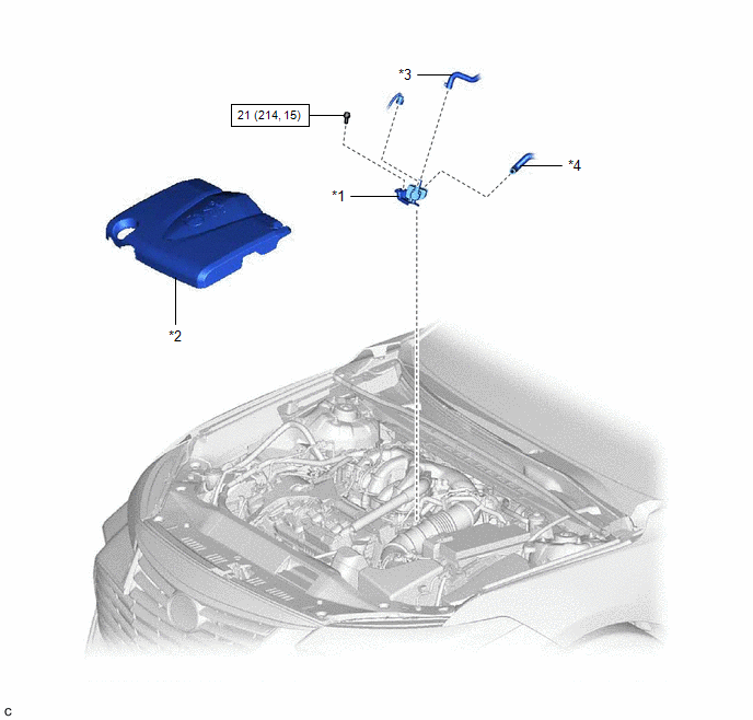
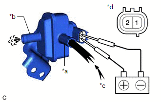
Inspection INSPECTION PROCEDURE 1. INSPECT PURGE VALVE (PURGE VSV) (a) Measure the resistance according to the value(s) in the table below. Standard Resistance:
If the result is not as specified, replace the purge valve (purge VSV).
Installation INSTALLATION PROCEDURE 1. INSTALL PURGE VALVE (PURGE VSV)
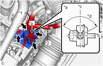
(b) Connect the No. 1 fuel vapor feed hose to the purge valve (purge VSV). (c) Connect the fuel vapor feed hose to the purge valve (purge VSV) and slide the clip to secure it. HINT: Engage the clip within the area shown in the illustration. (d) Connect the purge valve (purge VSV) connector. 2. INSTALL V-BANK COVER SUB-ASSEMBLY Click here Removal REMOVAL PROCEDURE 1. REMOVE V-BANK COVER SUB-ASSEMBLY Click here
2. REMOVE PURGE VALVE (PURGE VSV)
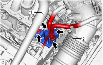
(b) Slide the clip and disconnect the fuel vapor feed hose from the purge valve (purge VSV). (c) Disconnect the No. 1 fuel vapor feed hose from the purge valve (purge VSV). (d) Remove the bolt and purge valve (purge VSV) from the intake air surge tank assembly. |
Toyota Avalon (XX50) 2019-2022 Service & Repair Manual > Airbag System(for Gasoline Model): System Description
SYSTEM DESCRIPTION FUNCTION OF SRS CONNECTORS (a) Location of activation prevention mechanism (b) Function of activation prevention mechanism (1) This mechanism is designed to create a short circuit automatically between the positive (+) and negative (-) terminals of a squib power source connector w ...