Toyota Avalon (XX50) 2019-2022 Service & Repair Manual: Voice Guidance Circuit between Radio Receiver and Stereo Component Amplifier

DESCRIPTION

This circuit is used when the voice switch of the steering pad switch assembly is pushed.

Using this circuit, the radio and display receiver assembly sends signals to the stereo component amplifier assembly.

WIRING DIAGRAM
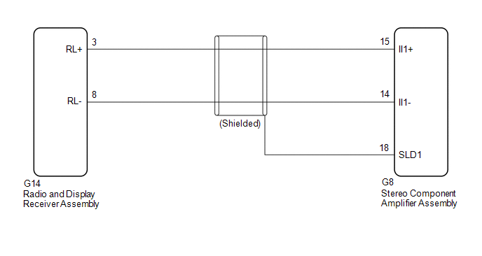
PROCEDURE

1.

CHECK HARNESS AND CONNECTOR (RADIO AND DISPLAY RECEIVER ASSEMBLY - STEREO COMPONENT AMPLIFIER ASSEMBLY)

(a) Disconnect the G14 radio and display receiver assembly connector.

(b) Disconnect the G8 stereo component amplifier assembly connector.

(c) Measure the resistance according to the value(s) in the table below.

Standard Resistance:

Tester connection

Condition

Specified condition

G14-3 (RL+) - G8-15 (II1+)

Always

Below 1 Ω

G14-8 (RL-) - G8-14 (II1-)

Always

Below 1 Ω

G8-18 (SLD1) - Body ground

Always

10 kΩ or higher

G14-3 (RL+) or G8-15 (II1+) - Body ground

Always

10 kΩ or higher

G14-8 (RL-) or G8-14 (II1-) - Body ground

Always

10 kΩ or higher

OK

PROCEED TO NEXT SUSPECTED AREA SHOWN IN PROBLEM SYMPTOMS TABLE

NG

REPAIR OR REPLACE HARNESS OR CONNECTOR

    Vehicle Speed Signal Circuit between Stereo Component Amplifier and Combination Meter

    Voice Guidance does not Function

    See More:

    Toyota Avalon (XX50) 2019-2022 Service & Repair Manual > Motor Generator Control System: Definition Of Terms
    DEFINITION OF TERMS Term Definition Monitor Description Description of what the motor generator control ECU monitors and how to detects malfunctions (monitoring purpose and its details). Related DTCs A group of diagnostic trouble codes that are output by the motor generator control ECU based on the ...

    Toyota Avalon (XX50) 2019-2022 Owners Manual

    Toyota Avalon (XX50) 2019-2022 Service & Repair Manual

    © 2024 Copyright www.tavalon.net
    0.0142