REMOVAL CAUTION / NOTICE / HINT The necessary procedures (adjustment, calibration, initialization, or registration) that must be performed after parts are removed and installed, or replaced during rear stabilizer bar removal/installation are shown below. Necessary Procedures After Parts Removed/Installed/Replaced (for Gasoline Model:)
CAUTION: To prevent burns, do not touch the engine, exhaust pipe or other high temperature components while the engine is hot.  PROCEDURE 1. REMOVE REAR WHEEL Click here 2. REMOVE NO. 2 FLOOR UNDER COVER (for Gasoline Model)
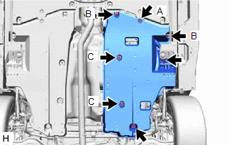
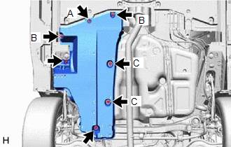
(b) Disengage the 2 grommets (B) and 2 clips (C) to remove the No. 2 floor under cover. 3. REMOVE NO. 1 FLOOR UNDER COVER (for Gasoline Model)
(b) Disengage the 2 grommets (B) and 2 clips (C) to remove the No. 1 floor under cover. 4. REMOVE CENTER EXHAUST PIPE ASSEMBLY for 2GR-FKS: Click here
for A25A-FXS: Click here
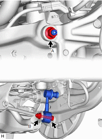
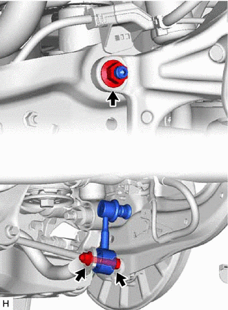
5. REMOVE REAR STABILIZER LINK ASSEMBLY LH
(b) Loosen the nut (B) of the rear stabilizer link assembly LH. NOTICE: Because the bolt has its own stopper, do not turn the bolt. Loosen the nut with the bolt secured.
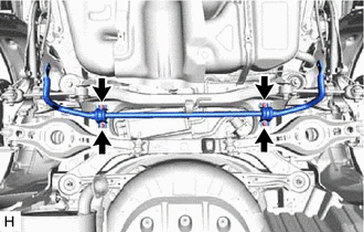
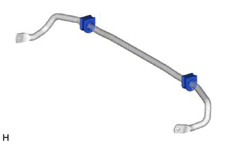
6. REMOVE REAR STABILIZER LINK ASSEMBLY RH HINT: Perform the same procedure as for the LH side. 7. REMOVE REAR STABILIZER BAR
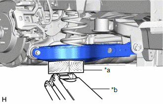
8. REMOVE REAR NO. 1 STABILIZER BAR BRACKET LH (a) Remove the rear No. 1 stabilizer bar bracket LH from the rear stabilizer bushing. 9. REMOVE REAR NO. 1 STABILIZER BAR BRACKET RH HINT: Perform the same procedure as for the LH side. 10. REMOVE REAR STABILIZER BUSHING
|
Toyota Avalon (XX50) 2019-2022 Service & Repair Manual > Meter / Gauge System(for Hv Model): Speedometer Malfunction
DESCRIPTION The combination meter assembly receives vehicle speed signals from the skid control ECU (brake booster with master cylinder assembly) via CAN communication. The speed sensor detects the wheel speed and sends the appropriate signals to the skid control ECU (brake booster with master cylin ...