DESCRIPTION The cooler compressor assembly receives refrigerant compression demand signals from the air conditioning amplifier assembly. Based on this signal, the cooler compressor assembly changes the amount of compressor output.
WIRING DIAGRAM 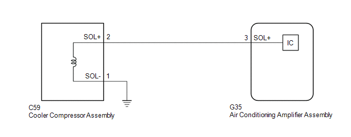 PROCEDURE
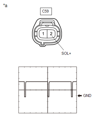
(a) Disconnect the C59 cooler compressor assembly connector. (b) Connect an oscilloscope to terminal C59-2 (SOL+) and body ground and check the waveform.
OK: Waveform is similar to that shown in the illustration.
(a) Disconnect the G35 air conditioning amplifier assembly connector. (b) Measure the resistance according to the value(s) in the table below. Standard Resistance:
|
Toyota Avalon (XX50) 2019-2022 Service & Repair Manual > Sliding Roof System(for Hv Model): Terminals Of Ecu
TERMINALS OF ECU CHECK SLIDING ROOF ECU (SLIDING ROOF DRIVE GEAR ASSEMBLY) (a) Disconnect the O3 sliding roof ECU (sliding roof drive gear assembly) connector. (b) Measure the resistance and voltage according to the value(s) in the table below. HINT: Measure the values on the wire harness side with ...


