|
Terminal No. (Symbol) | Wiring Color |
Terminal Description | Condition |
Specified Condition |
|
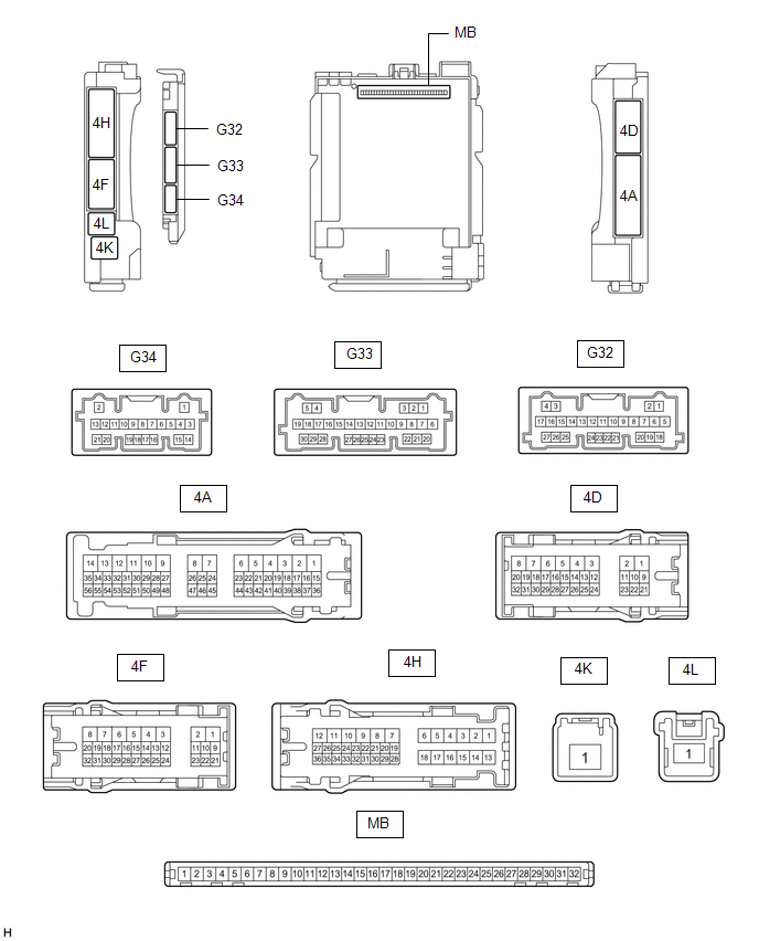
4A-17 - Body ground |
R - Body ground | IG power supply |
Engine switch on (IG) |
11 to 14 V |
| Engine switch off |
Below 1 V |
|
4A-30 - Body ground |
LG - Body ground |
ACC power supply | Engine switch on (ACC) |
11 to 14 V |
| Engine switch off |
Below 1 V |
|
4A-31 - Body ground |
V - Body ground |
Rear door courtesy light switch assembly (for RH) input |
Rear door RH open | Below 1 V |
|
Rear door RH closed | 11 to 14 V |
|
4A-36 - Body ground* |
SB - Body ground |
Front
door inside handle illumination light assembly LH and RH, center
console light (for passenger side) (No. 2 interior illumination light
sub-assembly), center console light (for driver side (No. 3 interior
illumination light sub-assembly) and cup holder light (for front side
and rear side) (No. 4 interior illumination light sub-assembly) drive
output | Front
door inside handle illumination light assembly LH and RH, center
console light (for passenger side) (No. 2 interior illumination light
sub-assembly), center console light (for driver side (No. 3 interior
illumination light sub-assembly) and cup holder light (for front side
and rear side) (No. 4 interior illumination light sub-assembly) off |
11 to 14 V |
| Front
door inside handle illumination light assembly LH and RH, center
console light (for passenger side) (No. 2 interior illumination light
sub-assembly), center console light (for driver side (No. 3 interior
illumination light sub-assembly) and cup holder light (for front side
and rear side) (No. 4 interior illumination light sub-assembly) dimmer
control operating (dimming) | Pulse generation |
|
Front
door inside handle illumination light assembly LH and RH, center
console light (for passenger side) (No. 2 interior illumination light
sub-assembly), center console light (for driver side (No. 3 interior
illumination light sub-assembly) and cup holder light (for front side
and rear side) (No. 4 interior illumination light sub-assembly) at full
brightness | Below 2.2 V |
|
4D-10 - Body ground |
R - Body ground |
Roof
console box sub-assembly, spot light assembly, vanity light (visor
assembly LH), vanity light (visor assembly RH), front footwell light LH
and RH (No. 1 interior illumination light assembly), rear footwell light
LH and RH (No. 6 interior illumination light sub-assembly) and front
console light (interior illumination light sub-assembly) power supply |
DOME CUT relay on | 11 to 14 V |
|
DOME CUT relay off | Below 1 V |
|
4D-12 - Body ground |
GR - Body ground |
Front door unlock detection switch RH input |
Front door RH locked |
11 to 14 V |
| Front door RH unlocked |
Below 1 V |
|
4D-13 - Body ground |
W - Body ground |
Front door unlock detection switch LH input |
Front door LH locked |
11 to 14 V |
| Front door LH unlocked |
Below 1 V |
|
4D-14 - Body ground |
GR - Body ground |
Rear door unlock detection switch LH input |
Rear door LH locked | 11 to 14 V |
|
Rear door LH unlocked |
Below 1 V |
|
4D-24 - Body ground* |
LG - Body ground | Front
door inside handle illumination light assembly LH and RH, center
console light (for passenger side) (No. 2 interior illumination light
sub-assembly), center console light (for driver side) (No. 3 interior
illumination light sub-assembly) and cup holder light (for front side
and rear side) (No. 4 interior illumination light sub-assembly) power
supply | Always |
11 to 14 V |
|
4D-29 - Body ground |
LA-G - Body ground | Illuminated entry system drive output |
Map light LH and map light RH (map light (roof console box sub-assembly)) off (when operated by illuminated entry system) |
11 to 14 V |
| Map light LH and map light RH (map light (roof console box sub-assembly)) on (when operated by illuminated entry system) |
Below 1 V |
|
4H-19 - Body ground |
LA-B - Body ground |
No. 1 luggage compartment light assembly and courtesy light assembly LH and RH power supply |
DOME CUT relay on | 11 to 14 V |
|
DOME CUT relay off | Below 1 V |
|
4H-24 - Body ground |
G - Body ground | Rear door courtesy light switch assembly (for LH) input |
Rear door LH open | Below 1 V |
|
Rear door LH closed | 11 to 14 V |
|
4H-34 - Body ground |
LA-GR - Body ground |
Luggage compartment door courtesy light switch (luggage compartment door lock assembly) input |
Luggage compartment door open |
Below 1 V |
| Luggage compartment door closed |
11 to 14 V |
|
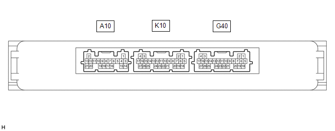
G32-20 (LSWR) - Body ground |
L - Body ground |
Rear door unlock detection switch RH input |
Rear door RH locked | 11 to 14 V |
|
Rear door RH unlocked |
Below 1 V |
|
G33-1 (FLCY) - Body ground |
W - Body ground | Front door courtesy light switch assembly (for LH) input |
Front door LH open | Below 1 V |
|
Front door LH closed |
11 to 14 V |
|
G33-2 (FLCL) - Body ground |
G - Body ground |
Courtesy light assembly LH drive output |
Courtesy light assembly LH off |
11 to 14 V |
| Courtesy light assembly LH on |
Below 1 V |
|
G33-3 (FRCL) - Body ground |
L - Body ground |
Courtesy light assembly RH drive output |
Courtesy light assembly RH off |
11 to 14 V |
| Courtesy light assembly RH on |
Below 1 V |
|
G33-6 (FRCY) - Body ground |
BE - Body ground |
Front door courtesy light switch assembly (for RH) input |
Front door RH open | Below 1 V |
|
Front door RH closed |
11 to 14 V |
|
G33-14 (ILSW) - Body ground* |
W - Body ground |
Mood switch signal input |
Mood switch off | 11 to 14 V |
|
Mood switch on | Below 1 V |
|
G33-20 (TCYL) - Body ground |
GR - Body ground |
No. 1 luggage compartment light assembly drive output |
No. 1 luggage compartment light assembly off |
11 to 14 V |
| No. 1 luggage compartment light assembly on |
Below 1 V |