DESCRIPTION The combination meter assembly and steering pad switch assembly are connected via direct line. The multi-information display in the combination meter assembly are operated using the switches of the steering pad switch assembly. WIRING DIAGRAM 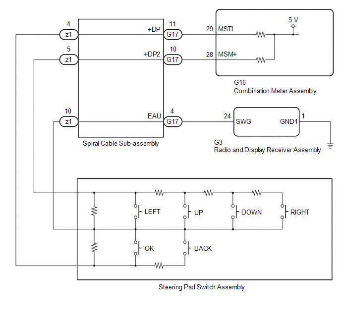 CAUTION / NOTICE / HINT NOTICE: When replacing the combination meter assembly, always replace it with a new one. If a combination meter assembly which was installed to another vehicle is used, the information stored in it will not match the information from the vehicle and a DTC may be stored. PROCEDURE
(a) Remove the steering pad switch assembly. Click here (b) Inspect the steering pad switch assembly. Click here
(a) Remove the spiral cable sub-assembly. Click here (b) Inspect the spiral cable sub-assembly. Click here
(a) Disconnect the G16 combination meter assembly connector. (b) Measure the resistance according to the value(s) in the table below. Standard Resistance:
(a) Connect the G16 combination meter assembly connector. (b) Measure the voltage according to the value(s) in the table below. Standard Voltage:
(a) Disconnect the G3 radio and display receiver assembly connector. (b) Measure the resistance according to the value(s) in the table below. Standard Resistance:
(a) Measure the resistance according to the value(s) in the table below. Standard Resistance:
|
Toyota Avalon (XX50) 2019-2022 Service & Repair Manual > Rear Door Belt Moulding: Installation
INSTALLATION CAUTION / NOTICE / HINT HINT: Use the same procedure for the RH side and LH side. The following procedure is for the LH side. PROCEDURE 1. PRECAUTION NOTICE: After turning the engine switch (for Gasoline Model) or power switch (for HV Model) off, waiting time may be required before disc ...


