DESCRIPTION When the taillight on, this circuit sends an illumination signal to the mobile wireless charger cradle assembly. WIRING DIAGRAM 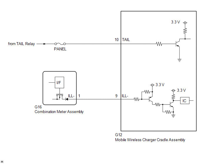 CAUTION / NOTICE / HINT NOTICE: Inspect the fuses for circuits related to this system before performing the following procedure. PROCEDURE
(a) Disconnect the G12 mobile wireless charger cradle assembly connector. (b) Measure the voltage according to the value(s) in the table below. Standard Voltage:
(a) Disconnect the G16 combination meter assembly connector. (b) Measure the resistance according to the value(s) in the table below. Standard Resistance:
|
Toyota Avalon (XX50) 2019-2022 Service & Repair Manual > Sfi System: Terminals Of Ecm
TERMINALS OF ECM HINT: The standard voltage, resistance and waveform between each pair of the ECM terminals is shown in the table below. The appropriate conditions for checking each pair of the terminals is also indicated. The result of checks should be compared with the standard voltage, resistance ...


