DESCRIPTION This is the power source circuit for the mobile wireless charger cradle assembly. WIRING DIAGRAM 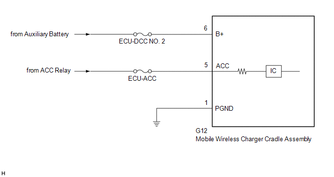 CAUTION / NOTICE / HINT NOTICE: Inspect the fuses for circuits related to this system before performing the following procedure. PROCEDURE
(a) Disconnect the G12 mobile wireless charger cradle assembly connector. (b) Measure the resistance according to the value(s) in the table below. Standard Resistance:
(c) Measure the voltage according to the value(s) in the table below. Standard Voltage:
|
Toyota Avalon (XX50) 2019-2022 Service & Repair Manual > Electronically Controlled Brake System(for Gasoline Model): Deceleration Sensor Internal Circuit (C1419,C1435)
DESCRIPTION These DTCs are stored when the skid control ECU (brake actuator assembly) receives an internal malfunction signal from the yaw rate and acceleration sensor (airbag sensor assembly). DTC No. Detection Item DTC Detection Condition Trouble Area C1419 Deceleration Sensor Internal Circuit Wit ...


