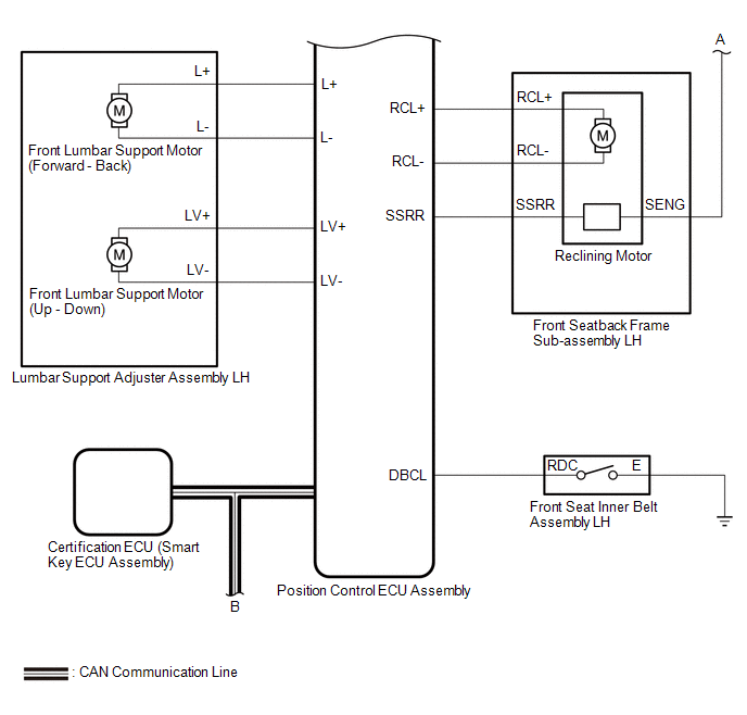
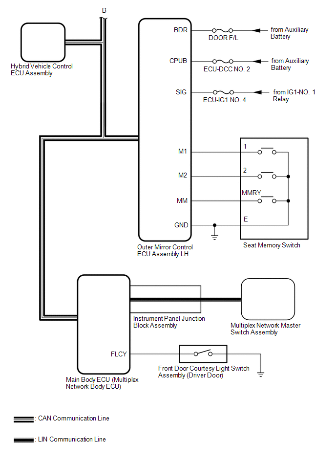
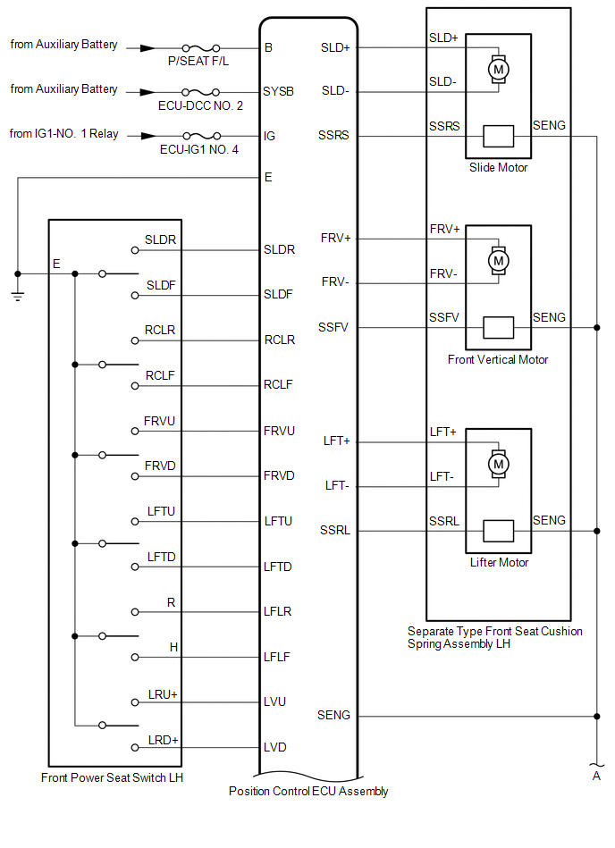
Toyota Avalon (XX50) 2019-2022 Service & Repair Manual: System Diagram

SYSTEM DIAGRAM

Communication Table

Sender

Receiver

Signal

Line

Hybrid Vehicle Control ECU Assembly

Main Body ECU (Multiplex Network Body ECU)

Shift position P signal

CAN

Outer Mirror Control ECU Assembly LH

Main Body ECU (Multiplex Network Body ECU)

  • M1 switch signal
  • M2 switch signal
  • SET switch signal

CAN

Main Body ECU (Multiplex Network Body ECU)

Position Control ECU Assembly

  • Shift position P signal
  • Transmission information
  • Driving position buzzer request
  • Driver seat position request
  • Driver seat position data

CAN

Certification ECU (Smart Key ECU Assembly)

Main Body ECU (Multiplex Network Body ECU)

  • Power switch signal
  • Memory call replay request
  • Key identification No. 1 to No. 7 acquisition condition

CAN

Position Control ECU Assembly

Main Body ECU (Multiplex Network Body ECU)

  • State signal of driver seat
  • State signal of driving position buzzer

CAN

Multiplex Network Master Switch Assembly

Main Body ECU (Multiplex Network Body ECU)

Door control switch signal

LIN

    System Description

    Terminals Of Ecu

    See More:

    Toyota Avalon (XX50) 2019-2022 Service & Repair Manual > Safety Connect System(for Hv Model): Backup Battery Failure (B15CC)
    DESCRIPTION This DTC is set when the DCM (Telematics Transceiver) detects one of the following: The BUB (Back-Up Battery) voltage drops or the BUB (Back-Up Battery) malfunctions. The BUB (Back-Up Battery) temperature is (temporarily) high. DTC No. Detection Item DTC Detection Condition Trouble Area ...

    Toyota Avalon (XX50) 2019-2022 Owners Manual

    Toyota Avalon (XX50) 2019-2022 Service & Repair Manual

    © 2024 Copyright www.tavalon.net
    0.0307