DESCRIPTION This circuit includes the navigation ECU and radio and display receiver assembly. WIRING DIAGRAM 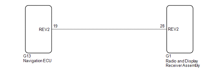 PROCEDURE
(a) Disconnect the G1 radio and display receiver assembly connector. (b) Disconnect the G13 navigation ECU connector. (c) Measure the resistance according to the value(s) in the table below. Standard Resistance:
|
Toyota Avalon (XX50) 2019-2022 Service & Repair Manual > Occupant Classification System(for Hv Model): Fail-safe Chart
FAIL-SAFE CHART FAIL-SAFE FUNCTION (a) The following chart shows the status of the front passenger SRS items and passenger airbag ON/OFF indicator operation under each condition. The passenger airbag ON/OFF indicator ("ON" and "OFF") comes on for approximately 4 seconds, then turns off for approxima ...


