Toyota Avalon (XX50) 2019-2022 Service & Repair Manual: Master Cylinder Pressure Sensor (C1246)

DESCRIPTION

The master cylinder pressure sensor is connected to the skid control ECU in the brake actuator assembly.

DTC No.

Detection Item

DTC Detection Condition

Trouble Area

C1246

Master Cylinder Pressure Sensor

Any of the following is detected:

  • The voltage of the sensor signal is out of range (below 0.129 V, above 3.29 V).
  • An abnormality is detected in the skid control ECU internal sensor test.
  • The sensor signal offset value is out of range.
  • Stop light switch assembly circuit
  • Master cylinder pressure sensor circuit
  • Master cylinder pressure sensor (brake actuator assembly)
DTC Detection Conditions: C1246
 

Vehicle Condition

Pattern 1

Pattern 2

Pattern 3

Diagnosis Condition

-

-

-

-

Malfunction Status

The voltage of the sensor signal is out of range (below 0.129 V, above 3.29 V).

-

-

An abnormality is detected in the skid control ECU internal sensor test.

-

-

The sensor signal offset value is out of range.

-

-

Detection Time

-

-

-

Number of Trips

1 trip

1 trip

1 trip

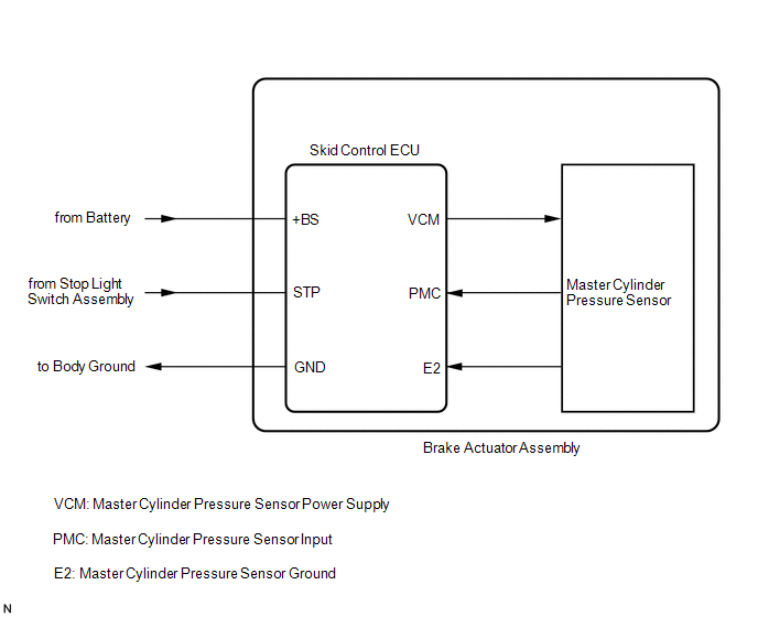
HINT:

DTC will be output when conditions for either of the patterns in the table above are met.

WIRING DIAGRAM

Refer to DTC C1249.

Click here

CAUTION / NOTICE / HINT

NOTICE:

When replacing the skid control ECU (brake actuator assembly), perform system variant learning and acceleration sensor zero point calibration.

Click here

PROCEDURE

1.

READ VALUE USING TECHSTREAM (BS1 VOLTAGE VALUE)

(a) Connect the Techstream to the DLC3.

(b) Turn the engine switch on (IG).

(c) Enter the following menus: Chassis / ABS/VSC/TRAC/EPB / Data List.

Chassis > ABS/VSC/TRAC/EPB > Data List

Tester Display

Measurement Item

Range

Normal Condition

Diagnostic Note

BS1 Voltage Value

+BS voltage value

Min.: 0.00 V, Max.: 20.00 V

-

Changes in proportion to battery voltage

Chassis > ABS/VSC/TRAC/EPB > Data List

Tester Display

BS1 Voltage Value

(d) Take a note of the +BS voltage value.

HINT:

The noted +BS voltage value is used in a later step.

NEXT

2.

CHECK STOP LIGHT OPERATION

(a) Check that the stop lights come on when the brake pedal is depressed, and go off when the brake pedal is released.

OK:

Condition

Illumination Condition

Brake pedal depressed

On

Brake pedal released

Off

NG

INSPECT LIGHTING SYSTEM (STOP LIGHT CIRCUIT)

OK

3.

READ VALUE USING TECHSTREAM (STOP LIGHT SWITCH ASSEMBLY)

(a) Connect the Techstream to the DLC3.

(b) Turn the engine switch on (IG).

(c) Enter the following menus: Chassis / ABS/VSC/TRAC/EPB / Data List.

Chassis > ABS/VSC/TRAC/EPB > Data List

Tester Display

Measurement Item

Range

Normal Condition

Diagnostic Note

Stop Light SW

Stop light switch assembly

ON or OFF

ON: Brake pedal depressed

OFF: Brake pedal released

-

Chassis > ABS/VSC/TRAC/EPB > Data List

Tester Display

Stop Light SW

(d) Check that the stop light switch assembly display observed on the Techstream changes according to brake pedal operation.

OK:

The Techstream displays on or off according to brake pedal operation.

NG

GO TO STEP 6

OK

4.

READ VALUE USING TECHSTREAM (MASTER CYLINDER PRESSURE SENSOR)

(a) Start the engine.

(b) Enter the following menus: Chassis / ABS/VSC/TRAC/EPB / Data List.

Chassis > ABS/VSC/TRAC/EPB > Data List

Tester Display

Measurement Item

Range

Normal Condition

Diagnostic Note

Master Cylinder Sensor

Master cylinder pressure sensor reading

Min.: 0.00 V, Max.: 5.00 V

Brake pedal released: 0.20 to 0.40 V

Reading increases when brake pedal is depressed

Chassis > ABS/VSC/TRAC/EPB > Data List

Tester Display

Master Cylinder Sensor

(c) Check that the brake fluid pressure value of the master cylinder pressure sensor observed on the Techstream changes when the brake pedal is depressed.

OK:

When the brake pedal is depressed, the voltage displayed on the Techstream increases.

NG

REPLACE BRAKE ACTUATOR ASSEMBLY

OK

5.

RECONFIRM DTC

(a) Clear the DTCs.

Chassis > ABS/VSC/TRAC/EPB > Clear DTCs

(b) Turn the engine switch off.

(c) Start the engine.

(d) Drive the vehicle and depress the brake pedal several times to test the stop light circuit.

(e) Check if the same DTC is output.

Chassis > ABS/VSC/TRAC/EPB > Trouble Codes

Result

Proceed to

C1246 is not output

A

C1246 is output

B

A

USE SIMULATION METHOD TO CHECK

B

REPLACE BRAKE ACTUATOR ASSEMBLY

6.

CHECK HARNESS AND CONNECTOR (STP TERMINAL)

(a) Turn the engine switch off.

*a

Front view of wire harness connector

(to Skid Control ECU (Brake Actuator Assembly))

(b) Make sure that there is no looseness at the locking part and the connecting part of the connector.

OK:

The connector is securely connected.

(c) Disconnect the A28 skid control ECU (brake actuator assembly) connector.

(d) Check both the connector case and the terminals for deformation and corrosion.

OK:

No deformation or corrosion.

(e) Measure the voltage according to the value(s) in the table below.

Standard Voltage:

Tester Connection

Condition

Specified Condition

A28-42 (STP) - Body ground

Stop light switch assembly on (Brake pedal depressed)

(+BS x 0.85) to 14 V*

A28-42 (STP) - Body ground

Stop light switch assembly off (Brake pedal released)

Below 1.5 V

HINT:

*: The minimum voltage value varies depending on the +BS terminal voltage value. The minimum voltage is 85% or more of the +BS terminal voltage.

OK

REPLACE BRAKE ACTUATOR ASSEMBLY

NG

REPAIR OR REPLACE HARNESS OR CONNECTOR (STP CIRCUIT)

    Low or High Power Supply Voltage (C1241)

    Open Circuit in Stop Light Switch Circuit (C1249)

    See More:

    Toyota Avalon (XX50) 2019-2022 Service & Repair Manual > Thermostat: Components
    COMPONENTS ILLUSTRATION *1 NO. 2 RADIATOR HOSE *2 WATER INLET WITH THERMOSTAT SUB-ASSEMBLY *3 GASKET *4 NO. 7 WATER BY-PASS HOSE N*m (kgf*cm, ft.*lbf): Specified torque ● Non-reusable part ...

    Toyota Avalon (XX50) 2019-2022 Owners Manual

    Toyota Avalon (XX50) 2019-2022 Service & Repair Manual

    © 2024 Copyright www.tavalon.net
    0.0116