DESCRIPTION |
DTC No. | Detection Item |
INF Code | DTC Detection Condition |
Trouble Area | MIL |
Note | | C1300 |
Skid Control ECU Malfunction |
1028 1029 1030 1031 1032 1033
1034 1035 1036 1037 1038 1039
1040 1041 1042 1043 1044 1045
1046 1047 1048 1049 |
- INF Code: 1028 to 1044, 1047 to 1049
- Skid control ECU (brake booster with master cylinder assembly) internal malfunction.
- INF Code: 1046
- Sudden drop of power source voltage or skid control ECU (brake booster with master cylinder assembly) internal malfunction.
- INF Code: 1045
- An open is detected in the brake booster pump assembly circuit or skid
control ECU (brake booster with master cylinder assembly) internal
malfunction.
|
- INF Code: 1028 to 1044, 1047 to 1049
- Skid control ECU (brake booster with master cylinder assembly)
- INF Code: 1046
- Auxiliary battery
- Hybrid control system (Charging circuit)
- Skid control ECU (brake booster with master cylinder assembly)
- INF Code: 1045
- Brake booster pump assembly
- Wire harness or connector
- Skid control ECU (brake booster with master cylinder assembly)
| Comes on |
- INF Code 1031 and 1032: SAE Code C0597 (Case 1)
- INF Code 1030 and 1033: SAE Code C0597 (Case 2)
- INF Code 1028: SAE Code C0597 (Case 3)
- INF Code 1029 and 1034 to 1049: SAE Code C0597 (Case 4)
- Electronically controlled brake system DTC
| MONITOR DESCRIPTION
The
skid control ECU (brake booster with master cylinder assembly) has a
self-diagnosis function. When an EEPROM, serial communication, CPU or IC
malfunction is detected during self-diagnosis, the skid control ECU
(brake booster with master cylinder assembly) illuminates the MIL and
stores a DTC. MONITOR STRATEGY |
Related DTCs | C0597 (Case 1): EEPROM malfunction C0597 (Case 2): Lost communication
C0597 (Case 3): CPU malfunction C0597 (Case 4): IC malfunction | |
Required Sensors/Components(Main) | Skid control ECU (brake booster with master cylinder assembly) | |
Required Sensors/Components(Related) | Skid control ECU (brake booster with master cylinder assembly) | |
Frequency of Operation | Continuous: C0597 (Case 1), C0597 (Case 2), C0597 (Case 3) and C0597 (Case 4)
During initial checking: C0597 (Case 1) and C0597 (Case 4) | |
Duration | -: C0597 (Case 1), C0597 (Case 3) and C0597 (Case 4)
0.06 seconds: C0597 (Case 2) | | MIL Operation |
Immediately | | Sequence of Operation |
None | TYPICAL ENABLING CONDITIONS All |
Monitor runs whenever the following DTCs are not stored |
None | C0597 (Case 4) |
Skid control ECU (brake booster with master cylinder assembly) state |
Initial check | TYPICAL MALFUNCTION THRESHOLDS C0597 (Case 1) |
Either of the following conditions is met | - | |
EEPROM write | Failure | |
EEPROM read | Failure | C0597 (Case 2) |
Either of the following conditions is met | - | |
Serial communication with low side IC |
Invalid | | Serial communication with high side IC |
Invalid | C0597 (Case 3) |
CPU function | Irregularity | C0597 (Case 4) COMPONENT OPERATING RANGE C0597 (Case 1) |
Both of the following conditions are met | - | |
EEPROM write | Success | |
EEPROM read | Success | C0597 (Case 2) |
Both of the following conditions are met | - | |
Serial communication with low side IC |
Valid | | Serial communication with high side IC |
Valid | C0597 (Case 3) C0597 (Case 4) |
Both of the following conditions are met |
- | | Skid control ECU (brake booster with master cylinder assembly) state |
Initial check | | IC function |
Normalcy | CONFIRMATION DRIVING PATTERN
- Connect the Techstream to the DLC3.
- Turn the power switch on (IG).
- Turn the Techstream on.
- Clear the DTCs (even if no DTCs are stored, perform the clear DTC procedure).
- Turn the power switch off.
- Turn the power switch on (IG).
- Turn the Techstream on.
- Enter the following menus: Chassis / ABS/VSC/TRAC / Trouble Codes.
- Read the DTCs.
HINT:
- If a DTC is output, the system is malfunctioning.
- If a DTC is not output, perform the following procedure.
- If the DTCs are not output, perform a universal trip and check for permanent DTCs.
Click here 
HINT:
- If a permanent DTC is output, the system is malfunctioning.
- If no permanent DTCs are output, the system is normal.
WIRING DIAGRAM Refer to DTCs C1252 and C1253.
Click here CAUTION / NOTICE / HINT
NOTICE: After
replacing the skid control ECU (brake booster with master cylinder
assembly), perform linear solenoid valve offset learning, ABS holding
solenoid valve learning, yaw rate and acceleration sensor zero point
calibration and system information memorization after performing "Reset
Memory". Click here PROCEDURE
(a) Clear the DTCs. Click here
Chassis > ABS/VSC/TRAC > Clear DTCs
(b) Turn the power switch off. (c) Turn the power switch on (IG).
(d) Check if the same DTC is output. Click here
Chassis > ABS/VSC/TRAC > Trouble Codes
| Result |
Proceed to | | A brake booster pump assembly circuit malfunction DTC is output with DTC C1300. |
A | | DTC C1300 is output. |
B | | DTC C0597 is output. |
C |
| A |
 | REPAIR CIRCUITS INDICATED BY OUTPUT DTCS |
| C |
| GO TO STEP 9 |
|
B |
 | |
| 2. |
CHECK FREEZE FRAME DATA | (a) Check the INF code from the Freeze Frame Data stored when DTC (C1300) was stored.
Click here Chassis > ABS/VSC/TRAC > Trouble Codes
|
Result | Proceed to | |
INF
code 1028, 1029, 1030, 1031, 1032, 1033, 1034, 1035, 1036, 1037, 1038,
1039, 1040, 1041, 1042, 1043, 1044, 1047, 1048 or 1049 is output. |
A | | INF code 1046 is output. |
B | | INF code 1045 is output. |
C |
| A |
| REPLACE BRAKE BOOSTER WITH MASTER CYLINDER ASSEMBLY |
| C |
| GO TO STEP 6 |
|
B | |
| |
| 3. |
CHECK FREEZE FRAME DATA | (a)
Using the Techstream, read the "IG1 Voltage Value", "IG2 Voltage
Value", "BS1 Voltage Value", "BS2 Voltage Value", "VM1 Voltage Value"
and "VM2 Voltage Value" of the Freeze Frame Data stored when the DTC
C1300 (INF code 1046) was stored. Click here
Chassis > ABS/VSC/TRAC > Trouble Codes
|
Result | Proceed to | |
Any of the voltage values of the Freeze Frame Data are 7.00 V or less. |
A | | All of the voltage values of the Freeze Frame Data are 12.00 V or more. |
B | HINT: If
any of the voltage values of the Freeze Frame Data are 7.00 V or less, a
sudden drop of the power source voltage is suspected as a cause of the
DTC output. In this case, inspect the auxiliary battery and replace or recharge the auxiliary battery as necessary.
| B |
| GO TO STEP 5 |
|
A | |
| |
| 4. |
CHECK AUXILIARY BATTERY | (a) Check the auxiliary battery voltage.
Standard Voltage: |
Tester Connection | Condition |
Specified Condition | |
Auxiliary battery | Power switch on (IG) |
11 to 14 V | |
Auxiliary battery | Power switch on (READY) |
11 to 15.5 V |
| OK |
| END |
| NG |
| CHARGE OR REPLACE AUXILIARY BATTERY |
| 5. |
CHECK AUXILIARY BATTERY | (a) Check the auxiliary battery voltage.
Standard Voltage: |
Tester Connection | Condition |
Specified Condition | |
Auxiliary battery | Power switch on (IG) |
11 to 14 V | |
Auxiliary battery | Power switch on (READY) |
11 to 15.5 V |
| OK |
| REPLACE BRAKE BOOSTER WITH MASTER CYLINDER ASSEMBLY |
| NG |
| CHARGE OR REPLACE AUXILIARY BATTERY |
| 6. |
INSPECT BRAKE BOOSTER PUMP ASSEMBLY |
| (a) Turn the power switch off. |
 |
|
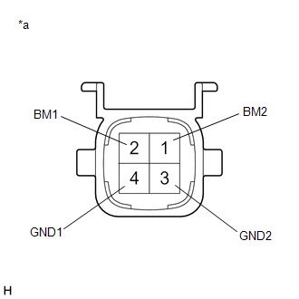
*a | Component without harness connected
(Brake Booster Pump Assembly) | | |
(b) Make sure that there is no looseness at the locking part and the connecting part of the connector.
OK: The connector is securely connected. (c) Disconnect the A40 brake booster pump assembly connector.
(d) Check both the connector case and the terminals for deformation and corrosion.
OK: No deformation or corrosion. (e) Measure the resistance according to the value(s) in the table below.
Standard Resistance: |
Tester Connection | Condition |
Specified Condition | |
2 (BM1) - 4 (GND1) | Always |
10 Ω or less | |
1 (BM2) - 3 (GND2) | Always |
10 Ω or less | |
2 (BM1) - 1 (BM2) | Always |
Below 1 Ω | |
4 (GND1) - 3 (GND2) | Always |
Below 1 Ω |
| NG |
| REPLACE BRAKE BOOSTER PUMP ASSEMBLY |
|
OK | |
| |
| 7. |
CHECK HARNESS AND CONNECTOR (GND TERMINAL) |
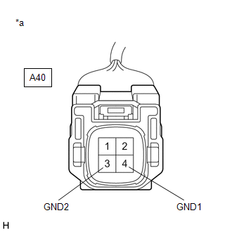
| (a) Measure the resistance according to the value(s) in the table below.
Standard Resistance: |
Tester Connection | Condition |
Specified Condition | |
A40-4 (GND1) - Body ground |
Always | Below 1 Ω | |
A40-3 (GND2) - Body ground |
Always | Below 1 Ω | |
 |
|
*a | Front view of wire harness connector
(to Brake Booster Pump Assembly) | | |
| NG |
| REPAIR OR REPLACE HARNESS OR CONNECTOR (GND CIRCUIT) |
|
OK | |
| |
| 8. |
CHECK HARNESS AND CONNECTOR (BRAKE BOOSTER WITH MASTER CYLINDER ASSEMBLY - BRAKE BOOSTER PUMP ASSEMBLY) |
(a) Make sure that there is no looseness at the locking part and the connecting part of the connector.
OK: The connector is securely connected. (b) Disconnect the A35 skid control ECU (brake booster with master cylinder assembly) connector.
(c) Check both the connector case and the terminals for deformation and corrosion.
OK: No deformation or corrosion. (d) Measure the resistance according to the value(s) in the table below.
Standard Resistance: |
Tester Connection | Condition |
Specified Condition | |
A35-1 (MRO1) - A40-2 (BM1) |
Always | Below 1 Ω | |
A35-1 (MRO1) or A40-2 (BM1) - Body ground |
Always | 10 kΩ or higher | |
A35-27 (MRO2) - A40-1 (BM2) |
Always | Below 1 Ω | |
A35-27 (MRO2) or A40-1 (BM2) - Body ground |
Always | 10 kΩ or higher |
| OK |
| REPLACE BRAKE BOOSTER WITH MASTER CYLINDER ASSEMBLY |
| NG |
| REPAIR OR REPLACE HARNESS OR CONNECTOR |
| 9. |
CHECK FREEZE FRAME DATA | (a)
Using the Techstream, read the "IG1 Voltage Value", "IG2 Voltage
Value", "BS1 Voltage Value", "BS2 Voltage Value", "VM1 Voltage Value"
and "VM2 Voltage Value" of the Freeze Frame Data stored when the DTC
C0597 was stored. Click here Chassis > ABS/VSC/TRAC > Trouble Codes
|
Result | Proceed to | |
Any of the voltage values of the Freeze Frame Data are 7.00 V or less. |
A | | All of the voltage values of the Freeze Frame Data are 12.00 V or more. |
B | HINT: If
any of the voltage values of the Freeze Frame Data are 7.00 V or less, a
sudden drop of the power source voltage is suspected as a cause of the
DTC output. In this case, inspect the auxiliary battery and replace or recharge the auxiliary battery as necessary.
| B |
| GO TO STEP 14 |
|
A | |
| |
| 10. |
CHECK AUXILIARY BATTERY | (a) Check the auxiliary battery voltage.
Standard Voltage: |
Tester Connection | Condition |
Specified Condition | |
Auxiliary battery | Power switch on (IG) |
11 to 14 V | |
Auxiliary battery | Power switch on (READY) |
11 to 15.5 V |
| NG |
| CHARGE OR REPLACE AUXILIARY BATTERY |
|
OK | |
| |
| 11. |
INSPECT BRAKE BOOSTER PUMP ASSEMBLY |
| (a) Turn the power switch off. | |
|
|
*a | Component without harness connected
(Brake Booster Pump Assembly) | | |
(b) Make sure that there is no looseness at the locking part and the connecting part of the connector.
OK: The connector is securely connected. (c) Disconnect the A40 brake booster pump assembly connector.
(d) Check both the connector case and the terminals for deformation and corrosion.
OK: No deformation or corrosion. (e) Measure the resistance according to the value(s) in the table below.
Standard Resistance: |
Tester Connection | Condition |
Specified Condition | |
2 (BM1) - 4 (GND1) | Always |
10 Ω or less | |
1 (BM2) - 3 (GND2) | Always |
10 Ω or less | |
2 (BM1) - 1 (BM2) | Always |
Below 1 Ω | |
4 (GND1) - 3 (GND2) | Always |
Below 1 Ω |
| NG |
| REPLACE BRAKE BOOSTER PUMP ASSEMBLY |
|
OK | |
| |
| 12. |
CHECK HARNESS AND CONNECTOR (GND TERMINAL) |
| (a) Measure the resistance according to the value(s) in the table below.
Standard Resistance: |
Tester Connection | Condition |
Specified Condition | |
A40-4 (GND1) - Body ground |
Always | Below 1 Ω | |
A40-3 (GND2) - Body ground |
Always | Below 1 Ω | |
|
|
|
*a | Front view of wire harness connector
(to Brake Booster Pump Assembly) | | |
| NG |
| REPAIR OR REPLACE HARNESS OR CONNECTOR (GND CIRCUIT) |
|
OK | |
| |
| 13. |
CHECK HARNESS AND CONNECTOR (BRAKE BOOSTER WITH MASTER CYLINDER ASSEMBLY - BRAKE BOOSTER PUMP ASSEMBLY) |
(a) Make sure that there is no looseness at the locking part and the connecting part of the connector.
OK: The connector is securely connected. (b) Disconnect the A35 skid control ECU (brake booster with master cylinder assembly) connector.
(c) Check both the connector case and the terminals for deformation and corrosion.
OK: No deformation or corrosion. (d) Measure the resistance according to the value(s) in the table below.
Standard Resistance: |
Tester Connection | Condition |
Specified Condition | |
A35-1 (MRO1) - A40-2 (BM1) |
Always | Below 1 Ω | |
A35-1 (MRO1) or A40-2 (BM1) - Body ground |
Always | 10 kΩ or higher | |
A35-27 (MRO2) - A40-1 (BM2) |
Always | Below 1 Ω | |
A35-27 (MRO2) or A40-1 (BM2) - Body ground |
Always | 10 kΩ or higher |
| OK |
| REPLACE BRAKE BOOSTER WITH MASTER CYLINDER ASSEMBLY |
| NG |
| REPAIR OR REPLACE HARNESS OR CONNECTOR |
| 14. |
CHECK AUXILIARY BATTERY | (a) Check the auxiliary battery voltage.
Standard Voltage: |
Tester Connection | Condition |
Specified Condition | |
Auxiliary battery | Power switch on (IG) |
11 to 14 V | |
Auxiliary battery | Power switch on (READY) |
11 to 15.5 V |
| OK |
| GO TO STEP 11 |
| NG |
| CHARGE OR REPLACE AUXILIARY BATTERY | | 

